I. INTRODUCTION
Zirconium alloys have been used in the nuclear industry for decades, as cladding materials, due to their superior corrosion resistance and low absorption cross-section for thermal neutrons. Current trends toward extending burnup, increased outlet temperatures and plant life extension in nuclear power facilities require a better mechanistic understanding of the corrosion under irradiation. The life-limiting factors for Zircaloy-4 in a reactor are normally corrosion and embrittlement caused by hydrogen absorption. Since essentially, all of the hydrogen absorbed into the metal was created during the corrosion process, it is crucial to understand the role of radiation-enhanced corrosion, hence, its impact on radiation-enhanced hydrogen absorption.
Studies based on in-pile and out-of-pile weight gain data suggest that neutron radiation has a large impact on the corrosion rate of zirconium alloys during the service. Reference Garzarolli, Broy, Busch, Bradley and Sabol1,Reference Iltis, Lefebvre and Lemaignan2 Garzarolli et al., Reference Garzarolli, Broy, Busch, Bradley and Sabol1 showed a comparison of the in-pile pressurized water reactor (PWR) data with the out-of-pile behavior of Zircaloy-4 in deionized water, which indicates the same corrosion behavior up to a weight gain of about 50 mg/dm2, which is the equivalent of 3.4 µm of oxide (14.7 mg/dm2 ≈ 1 µm oxide Reference Ghosal, Palit and De3 ), after which it is enhanced by irradiation. At higher fluences, the corrosion rate is increased by a factor of five, indicating that radiation had an increase in corrosion rate under reactor operating conditions. Asher et al. Reference Asher, Davies and Kirstein4 found that zirconium irradiated in-reactor in moist carbon dioxide–air mixtures had oxygen weight gains of more than five times that in the unirradiated state. Bradhurst et al. Reference Bradhurst, Shirvington and Heuer5 observed in-reactor corrosion rates that were ten times greater than those conducted out-of-reactor and attributed part of the difference to greater permeability of the oxide irradiated in-reactor. Furthermore, old data on in-reactor exposure of Zircaloy-2 show an increase in oxide weight gain of 40-fold and a strong linear dependence with neutron flux. Reference Johnson and Irvin6 These data suggest that displacement damage to the solid during corrosion produces a significantly larger effect than does radiolysis alone. However, the true driving force for such enhanced corrosion remains unclear.
From the extensive use of zirconium alloys as components in nuclear reactors has come clear evidence that reactor radiation is a major corrosion parameter. Cox Reference Cox7 reviewed the subject and summarized a number of factors that could influence zirconium alloy oxidation under irradiation, which include radiation type, intensity and fluence, coolant chemistry, alloy composition, metallurgical condition, surface condition, temperature, and proximity to dissimilar metals.
The majority of studies on out-of-pile zirconium corrosion at temperatures relevant to reactor operation suffer from three problems (1) the absence of irradiation effects, (2) low corrosion rates even at high temperatures, and (3) very long testing times to differentiate between material variables. The majority of studies on corrosion behavior of reactor materials were conducted using ex situ experiments due to limited access of irradiation sources. Two paths were usually taken to evaluate the effects of irradiation on corrosion: exposure of pre-irradiated specimen in high temperature water; and irradiation of a pre-corroded specimen and then exposing it to high temperature water once more. In post-irradiation exposures, the difference in term of oxide layer thickness was insignificant, indicating that ex situ experiments cannot fully represent the nuclear reactor environment. Woo et al., Reference Woo, McDougall, Hutcheon, Urbanic, Griffiths, Coleman, Sabol and Moan8 carried out a post-irradiation experiment using electrons on Zircaloy-2 and found no effect on corrosion behavior. Cheng et al. Reference Cheng, Kruger, Adamson, Garde and Bradley9 did not observe accelerated corrosion of neutron-irradiated Zircaloy-4 during post-irradiation exposure in 316 °C water for oxide thickness less than 3 µm. To determine the effects of radiation on corrosion, irradiation must be conducted in situ. These effects can be of multiple origins and include radiolysis of the coolant, changes in the metallurgical condition, enhanced kinetics, or phase transformations.
Irradiation-accelerated corrosion can take place in at least three different ways. First, interaction between ionizing radiation and water molecules produces a variety of reaction products, such as oxidizing species O2, O·, HO2, and H2O2 that could accelerate the corrosion through an increase in corrosion potential. Second, irradiation of the solid surface will produce electronically excited states (excitons), trapped electrons and “holes” that can contribute to the corrosion kinetics. Reference LaVerne10–Reference Cox, Fidleris, Van Swam and Eucken13 Lastly, displacement damage produces a high concentration of defects that can increase the diffusion coefficient and accelerate corrosion reactions. Aqueous corrosion of zirconium alloys in the temperature range from 250–400 °C occurs by the diffusion of oxygen via oxygen vacancies in the oxide layer; the corrosion rate can be affected by the properties of the oxide layer formed during exposure, including oxide morphology, oxide phase, stress, etc. In the oxide, the displacement of ions from their lattice sites by neutron/ion irradiation could lead to enhanced point defect concentrations, enhanced diffusion, which would lead to accelerated corrosion. Formation of electron hole pairs and Compton electrons by radiation could also theoretically lead to a significant increase in electron conduction in the oxide (i.e., radiation-enhanced electrical conductivity). Precipitate dissolution may also occur due to ballistic mixing by a primarily knock-on effect, lead to change of relative concentration of alloy element between precipitate and matrix, which can also affect local corrosion rate.
Second phase particles (SPP) in Zircaloy-4, rich in Fe and Cr content, are noble compared with zirconium matrix and oxidize at a slower rate than the matrix, as observed by Iltis et al. Reference Iltis, Lefebvre and Lemaignan2 Franklin and Lang Reference Franklin, Lang, Eucken and Garde14 also suggested that SPPs found in the oxide adjacent to the metal/oxide (M/O) interface have a lower potential than that required for their cations to oxidize. As a result, SPPs can remain unoxidized until the oxide is thick enough to insulate them from the metal substrate. Pêcheur et al. Reference Pêcheur, Lefebvre, Motta, Lemaignan, Charquet, Garde and Bradley15 observed that particle amorphization occurs on the periphery of Zr(Cr, Fe)2 precipitates, under neutron irradiation to fluences of 4.0 and 5.4 × 1025 n/m2 (E > 1 MeV) or ∼10 dpa at 316 °C [a fluence of 4.4 × 1024 n/m2 (E > 1 MeV) is required to create 1 dpa of irradiation damage in zirconium Reference Fidleris, Tucker, Adamson, Adamson and Van Swam16 ]. Fe depletion from the SPPs during both in-reactor corrosion and autoclave tests has been reported; however, Bradley and Perkins Reference Bradley and Perkins17 also observed an anomalous Cr depletion from an oxidized Zr(Cr, Fe)2 in an unirradiated thick porous oxide. Their observation that chromium depletes, but not iron, could be a result of faster diffusion of Cr in the zirconium oxide matrix.
This study will focus on the characterization of the oxide film formed on Zircaloy-4 that has been exposed to the PWR primary loop environment (without B and Li addition) during proton irradiation. The oxides and SPPs were characterized for both the irradiated and unirradiated states to understand the effect of simultaneous irradiation during corrosion.
II. EXPERIMENT
An in situ corrosion-irradiation experiment conducted in a dedicated beamline at the Michigan Ion Beam Laboratory (MIBL) was used to study the simultaneous irradiation and corrosion of Zircaloy-4.
A. Irradiation-accelerated corrosion facility
A 1.7-MV Tandetron accelerator at MIBL was used to produce proton energies up to 3.4 MeV with a target current up to 60 µA. The beam was raster-scanned over an area of 8 × 8 mm on the slits system, which has a 6 × 6 mm opening to allow the beam to pass through. The beam current was also monitored and recorded on each slit to ensure beam position was maintained with respect to each slit. After passing through the slits, the beam passes through a 2.1-mm diameter circular aperture on the back of the sample mount to define the exposed area of the sample.
Deionized water bubbled with hydrogen gas was used to simulate the 3 wt ppm H2 PWR water chemistry. Dissolved oxygen (DO) and water conductivity was recorded on both the inlet and outlet of the corrosion cell during the experiment. A pair of high-pressure pumps and a back-pressure-regulator was used to build up pressure in the cell and to maintain the cell pressure above vapor pressure that prevents water from boiling at high temperatures.
The corrosion cell was designed to contain a 10 mL volume of flowing water at high temperature and pressure, while providing access for in situ diagnostic probes. The flow rate of the water that passed through the cell was kept at 10 mL/min, which ensured that there was no turbulence in the cell. A heat exchanger was used to heat up the inlet water using the heat from the outlet water. The cell body was heated by external heating bands and the cell assembly was wrapped with fiberglass insulation tape to minimize temperature variation during the experiment. The cell internal temperature was controlled by a proportional-integral-derivative (PID) controller, which utilized an internal thermocouple.
A safety system consisting of fast closing valves and pressure sensors was built into the beamline to protect the accelerator from damage in the event of sample rupture. In the event of sample rupture, the two pressure sensors that were situated in close proximity of the sample would trigger the fast valves to close. The typical response time is in the order of milliseconds. A more elaborate description of the experimental setup can be found in Ref. Reference Raiman, Flick, Toader, Wang, Samad, Jiao and Was18.
B. Sample design and fabrication
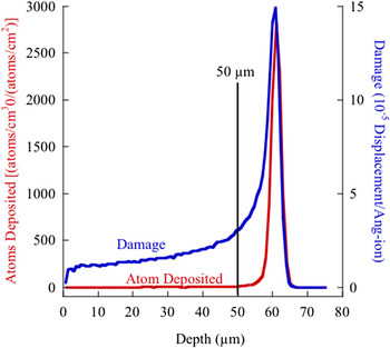
The sample was designed to allow the protons to fully pass through the sample while simultaneously being exposed to high-temperature high-pressure water on one side and a high vacuum on the other. As a result, thickness and uniformity of the sample were tightly controlled. The design window for thickness was determined by simulating the proton depth range in zirconium metal. Figure 1 shows the range and damage curve in zirconium for 3.2 MeV protons as calculated by TRIM 2013 Reference Ziegler19 in simple Kichin-Pease mode. The final sample thickness was chosen such that the ions penetrated through the entire sample thickness and that the damage variation across the sample thickness was minimized, leading to a final sample thickness of 50 µm.
Damage and ion range plots for 3.2-MeV protons in zirconium metal as calculated by TRIM 2013 Reference Ziegler19 in the Kinchin-Pease mode with a displacement energy of 40 eV for zirconium. 20

Disks with a diameter of 7.6 mm were cut from a 400-µm thick sheet of Zircaloy-4 using electrical discharge machining. The disks then pre-thinned on both sides using a disk grinder (Gatan 623) on a grinding wheel with SiC abrasive paper (grit 400–1200) to a thickness of ∼55 ± 2 µm to ensure that the two surfaces of the disks are flat and parallel. The disks were then mechanically polished on a polishing pad using 1 and 0.5 µm diamond paste to a thickness of 52 ± 1 µm. The final polishing was performed using 0.05-µm colloidal silica suspension (pH ∼ 10) to a sample thickness of 50 µm. The basic colloidal silica solution removes material both chemically and mechanically, to give the sample a damage-free surface. Sample thickness was measured between each grinding and polishing steps using a digital drop indicator with a resolution of 1 µm. After final polishing, the disk was sandwiched between a zirconium washer and a sample mount that were then laser welded to add structural rigidity and support to the sample.
C. In situ irradiation–corrosion experiments
Ion irradiations were performed using 3.2 MeV protons at a current density of 2 µA/cm2 at 320 °C. A total of four samples of Zry-4 were tested in 320 °C primary water with 3 wt ppm H2 (35 cc/kg). One sample was irradiated for 24 h, and a second sample was irradiated for 72 h. The displacement damage (expressed in displacements per atom, dpa) was calculated from the proton flux using displacement energy of 40 eV for zirconium. 20 Under normal irradiation conditions, the damage rate was about 4.4 × 10⁻⁷ dpa/s. The damage profile induced in the sample by the incident protons was calculated using the software TRIM2013. Reference Ziegler19 Two samples were exposed without irradiation. Experimental conditions are reported in Table I.
List of sample used in this study.

Deionized water was treated using a UV light and an ion exchange filter to remove any organic/inorganic compounds that may be present in the water. Pure hydrogen gas was used to purge the water and to hydrogenate it to a level of 3 wt ppm, yielding a hydrogen overpressure of 0.9 MPa (∼13.2 psig). DO was measured using Mettler Toledo Thornton® DO sensors, and water conductivity was measured using an Omega® conductivity sensor. Both measurements were made on the inlet and the outlet lines. Prior to the start of an experiment, the water was allowed to circulate in the system until conductivity, and DO levels dropped below a typical value of 0.2 µS/cm and 10 wt ppb, respectively. Typical heat-up time of the cell before the start of the irradiation was 3 h. After achieving temperature stability, the proton beam was applied to the sample. Beam heating was insignificant (<1 °C), measured by an infrared pyrometer from the vacuum-facing side of the sample, at the highest current density of 2 µA/cm2, and the PID controller quickly adjusted the cell temperature to 320 °C. Before the irradiation, the proton beam current was measured both on the slits and in the Faraday cup (immediately after the slits). Routine beam current checks were performed by periodically inserting a Faraday cup for 2–3 min during the experiment.
To provide a reference for in situ irradiation–corrosion experiment, samples from the same batch of material were exposed in a recirculating autoclave at 320 °C, with hydrogenated water (3 wt ppm H2) for the duration of 53 days.
D. Post-irradiation characterization
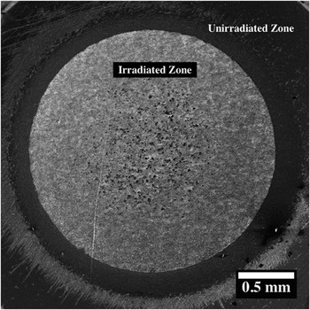
Focused ion beam (FIB) milling was used to create cross-sectional sample for oxide thickness measurement and lamella for transmission electron microscopy (TEM). Oxide thickness measurements were determined from cross-sections, in which a 150 × 50-µm cross-sectional area, covering the entire thickness of the sample was milled by FIB, and backscattered electron imaging (BSE) was used to obtain information about the oxide thickness and SPP distribution. For the irradiated samples, two specific areas were chosen to compare their oxide thickness, the irradiated zone (IR) and the unirradiated zone of the irradiated sample (IR-UI) shown in Fig. 2. For the unirradiated reference sample, the oxide thickness measurement was taken from the center of the sample.
SEM image of the surface of the 24-h irradiated sample 24IR, the irradiated and unirradiated zone.

The oxide morphology was characterized in bright field (BF) and annular dark field mode using a JEOL 2100F STEM. High-resolution TEM (HRTEM) images and selective area electron diffraction (SAED) patterns were obtained using JEOL 3011 TEM with an acceleration voltage of 300 kV. The SAED pattern was indexed, and the zone axis was determined, and the lattice parameters calculated from the diffraction pattern were then compared with the powder diffraction file found in JCPDS database. 21
Energy dispersive x-ray spectroscopy (EDS) line scans were taken using a FEI Helios SEM. FIB-thinned TEM samples with a thickness of 30–50 nm were used in this analysis. EDS data were collected using a 30-kV electron beam at a current of 0.2 nA.
The Raman spectra were recorded using a Renishaw® inVia microscope with a RenCam CCD detector. The spectra were collected using a 633-nm wave length laser, at a typical laser power of 50 mW, during a total of 500 s.
III. RESULTS
In this section, the main focus is to characterize oxide films on samples formed in the in situ irradiation–corrosion experiment and autoclave experiment. Aspects investigated include oxide morphology, oxide thickness, and second-phase stability during corrosion.
A. Oxide characterization
Characterization of the oxide focused on the 24-h irradiated sample (24IR/24IR-UI), a 72-h irradiated sample (72IR/72IR-UI), and a sample exposed for 53 days in the unirradiated condition (53UI). The 72-h irradiated sample was characterized for oxide thickness only.
1. Unirradiated, reference sample 53UI
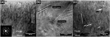
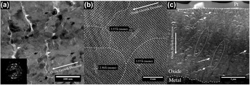
The oxide of the reference sample 53UI had a thickness of ∼1 µm and consisted of a columnar grain morphology in which the grains had a width of 20–30 nm and length of ∼100 nm [Fig. 3(a)]. Morié fringe contrast was also observed in the oxide, which is caused by the stacking of several crystallites with a slight misorientation in the thickness of the FIB lamella. Columnar grains with the long-axis orientation perpendicular to the M/O interface were found in the entire oxide scale. The preferential grain orientations were also evident from electron diffraction patterns [Fig. 3(a) inset]. The similarities found between the diffraction patterns taken at different locations across the oxide layer suggested that the oxide grains were preferentially orientated throughout the thickness. The ring patterns were analyzed to determine the d-spacings and were compared with literature data obtained for monoclinic (JCPDS 88-2390, 37-1484) and t-ZrO2 (JCDPS 50-1089, 79-1771). 21 The oxide consists of mainly monoclinic zirconia (m-ZrO2), since no tetragonal diffraction patterns were identified. HRTEM images, shown in Fig. 3(b), confirmed a d-spacing of 5.09 Å for the (001) plane compared with the literature value of 5.08 Å, and a d-spacing of 3.51 Å for the (011) plane compared with 3.63 Å in the literature. A few large cracks (∼50–100 nm long and ∼10–20 nm wide) were found parallel to the M/O interface [Fig. 3(c)]. These cracks were isolated and had no connection to the outer surface of the oxide.
(a) TEM BF image of reference sample 53UI, inset shows SAED diffraction pattern of the oxide, (b) HRTEM image of monoclinic zirconia columnar grains, and (c) lateral cracks indicated by the arrows.

2. Irradiated sample IR24
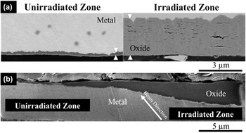
Characterization of the oxide was performed on the sample 24IR. The sample geometry is shown in Fig. 2, which reveals a clear boundary between the irradiated and unirradiated zones. Cross-sections for SEM imaging and TEM lamella samples were taken from the corresponding areas. The thickness of the oxide layer, evaluated by the cross-sectional BSE image was ∼3 µm in the irradiated zone and ∼0.3 µm in the unirradiated zone [Fig. 4(a)]. The sharpness of the transition between the irradiated and unirradiated zones is shown in Fig. 4(b), which indicated that the transition region was about 20 µm wide. The sharpness was achieved with a 2.1-mm aperture placed at the back of the sample, ∼1 cm from the sample back surface. Proton beam direction was not perpendicular to the sample surface at the peripheral of the irradiated zone, and the actual divergence of the beam was insignificant.
BSE image of oxide thickness comparison (a) between unirradiated zone (IR24UI) and irradiated zone (IR24) on the 24-h irradiated sample shown in Fig. 2(b). (b) Transition between the unirradiated and irradiated zones of sample IR24.

a. Irradiated zone of IR24
A thin oxide layer, ∼100 nm in thickness, was formed during heating of the sample and prior to the application of the proton beam. Beneath this early oxide layer, the microstructure exhibited equiaxed m-ZrO2 grains with an average grain size of 20–30 nm [Fig. 5(a)]. The oxide thickness was ∼3 µm. This equiaxed grain structure continued to M/O interface with occasional areas where small clusters of columnar grains were observed. The similar contrast observed in the TEM image suggested that the majority of the grains in the oxide were orientated in the oxide growth direction. The electron diffraction pattern of the oxide layer corresponded to nanocrystalline material with preferential orientations (i.e., broken rings) as shown in Fig. 5(a) (inset). Analysis of the diffraction patterns revealed that the oxide was mainly m-ZrO2, consistent with the results of an HRTEM analysis carried out on this oxide [Fig. 5(b)]. Oxide phase was identified as monoclinic ZrO2, with an orientation of (110)[001]m parallel to the oxide growth direction. The d-spacing was 3.57 Å compared with literature values of 3.63 Å found on pure m-ZrO2. 21
(a) TEM BF image of oxide grains with an equiaxed grain structure in the irradiated sample 24IR, inset of ED pattern shown monoclinic zirconia, intergranular pores and lateral cracks are indicated with back and white arrows, respectively (b) HRTEM micrograph of oxide grain formed on IR24-irradiated region, and (c) lateral cracks are indicated by arrows.

Microcracks of various sizes were found throughout the oxide thickness, Fig. 5(c), ranging from 100 to 500 nm in length and 10–50 nm in width, and at a higher density compared to that in sample 53UI. The finer cracks or pores seemed to propagate in an intergranular manner as indicated by the arrows in Fig. 5(a). In some areas, the finer cracks had formed on top of each other creating a band in the oxide along the growth direction, as indicated by the circle in Fig. 5(c). In addition to cracks, a network of intergranular defects or fine pores at crystallite boundaries was also observed within the oxide [Fig. 5(a)].
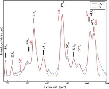
Raman spectroscopic analysis of sample 24IR was used to verify the oxide phases, Fig. 6. After peak fitting, the positions of the peaks were found to be in good agreement with the literature values on m-ZrO2. Reference Barberis, Merle-Méjean and Quintard22
Experimental and fitted Raman spectra of 24IR oxide, wave numbers for monoclinic and tetragonal phases are labeled with m and t, respectively.

b. Unirradiated zone of IR24UI
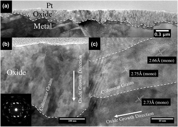
The oxide in the unirradiated region of irradiated sample IR24 resembled that of sample 53UI exposed in the autoclave without irradiation. Oxide thickness measured by BSE cross-sectional image and TEM image confirmed that the thickness was about 0.3 µm. The oxide structure in the unirradiated zone of sample IR24UI, Fig. 7(a), appeared to be very similar to that found on the oxide of reference sample (53UI) formed in the autoclave. The layer consisted of columnar, m-ZrO2 grains 20–30 nm in width and 50–100 nm in length [Fig. 7(b)], with very strong preferred orientations, as shown in its electron diffraction pattern [Fig. 7(b) inset]. HRTEM image [Fig. 7(c)] also confirmed the oxide phase to be m-ZrO2. The lattice spacing of the oxide was measured as 2.66–2.75 Å, for the (111)m plane that was perpendicular to the M/O interface (compared with the literature value of 2.84 Å 21 ). There is a 5% error associated with the TEM measurement, which could account for the smaller d-spacing. No lateral cracks or intergranular cracks were observed in this oxide.
(a) TEM BF image of oxide found on the IR24UI sample (unirradiated zone), with an average oxide thickness of 0.3 µm, (b) oxide consists of columnar grains, and (c) HRTEM image of monoclinic columnar grains.

c. Irradiated sample IR72
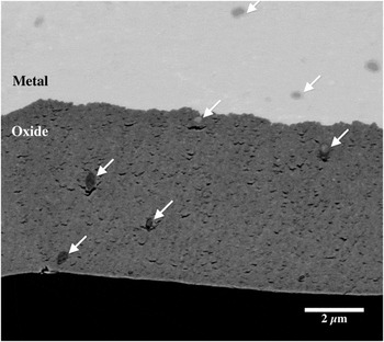
BSE imaging was used to determine the oxide thickness from FIB cross-sections extending over a span of 150 µm. The different contrast between oxide and metal under BSE imaging mode made the oxide layer distinguishable from the substrate [Fig. 8]. The average oxide thickness was measured to be 4.75 µm in the irradiated zone and ∼0.3 µm in the unirradiated zone. Oxide morphology in the irradiated region of sample 72IR was similar to that for the 24IR oxide. As a result, 72IR was characterized for oxide thickness only.
BSE image of oxide formed on sample 72IR; SPPs are indicated by arrows.

B. SPPs
SPPs in the metal, oxide and oxide/metal interface regions of sample IR24 were characterized using analytical microscopy. TEM imaging was used to identify the locations of SPPs within the oxide, and SAED was used to obtain crystallographic information about its phase. EDS line scans were used to obtain chemical profiles across the SPPs, especially the Cr/Fe ratio and their distribution. The oxygen detected in metallic precipitates could be ascribed to oxygen contamination from the air on the FIB sample. SPPs in the oxide in sample 53UI were not characterized because the oxide was only 1-µm thick, and the SPPs were not oxidized. The irradiated oxide (IR24) had an oxide layer of ∼3 µm, which was ideal for characterizing SPP evolution under irradiation.
1. SPPs embedded in the metal
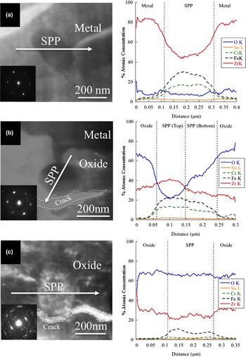
SPPs ranging from 100 to 200 nm in size were randomly distributed in the zirconium metal. The SPPs in the metal matrix remained in the intermetallic form after irradiation. EDS line profiles showed that the SPP was rich in Fe and Cr, Fig. 9(a). An SAED pattern [Fig. 9(a) inset] of the SPP embedded in the metal was indexed as hexagonal close packed structure Zr(Fe,Cr)2; Laves phase with a C14 crystal structure, in good agreement with measurements by Motta et al. Reference Motta, Erwin, Delaire, Birtcher, Chu, Maser, Mancini, Lai, Moan and Rudling23 in Zircaloy-4. The total dose received by the sample was very low, ∼0.13 dpa, amorphization of the SPPs was not observed. From the EDS line profile shown in Fig. 9(a), it was determined that the precipitates in the metal had a Fe/Cr ratio of 1.5–1.7, which was also in good agreement with the previously reported value. Reference Iltis, Lefebvre and Lemaignan2
TEM image, EDS line profile and Fe/Cr profile of the SPP on sample IR24, (a) within the metal, (b) metal/oxide interface, (c) in oxide, fully oxidized.

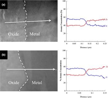
O and Zr concentration profiles across the metal/oxide interface for sample (a) 24IR and (b) 24IR-UI.

2. SPPs at metal/oxide interface
Delayed oxidation process of SPPs was observed when SPPs were recently incorporated in the growing oxide. The SPPs were still metallic, however, oxygen enrichment was observed in some of the particles, determined by the change in contrast in the TEM image. Figure 9(b) shows a case in which the oxide growth front had just incorporated the SPP into the oxide matrix. A portion of precipitate facing the M/O interface remains as metal, but the portion facing the oxide/environment interface showed a significantly higher oxygen concentration [EDS profile in Fig. 9(b)]. The presence of rings within the diffraction pattern indicated that there might be amorphous/nanocrystallite regions present within the SPP, especially the oxygen-enriched regions where oxide nucleation upon oxygen saturation could occur. The Fe/Cr ratio of these SPPs was the same as those found in the metal matrix, about 1.6–1.7.
The oxide adjacent to the SPP had the same diffraction pattern as the bulk oxide, indicating that there was no tetragonal phase present in the immediate vicinity of the particles. At the early stage of SPP incorporation into the oxides, a crescent crack formed on the side facing the outer surface was observed, as indicated by the dotted region in Figs. 9(b) and 9(c).
3. SPPs in the oxide
The SPPs deeper into the zirconia oxide layer were fully oxidized and had an elongated shape, characteristic of an anisotropic oxide growth direction [Fig. 9(c)]. The Fe and Cr concentration dropped significantly, indicating outward diffusion of alloying elements during oxidation of SPPs. Diffraction patterns taken from the oxidized SPPs [Fig. 9(c) inset] suggested that the precipitates became fully oxidized and crystallite sizes within the SPP were comparable to the oxide matrix grain sizes. Similar preferential orientation was observed on the crystallites formed within the SPPs, compared with the surrounding oxide matrix.
C. Metal/oxide interfacial chemical profile
EDS in SEM was used for chemical profiling across the M/O interface on the irradiated sample 24IR. Oxygen and zirconium profiles were measured at steps of 5–10 nm. The analysis covered a distance of ∼75–125 nm on both sides of the interface. The concentration profiles in at.% are shown in Fig. 10(a). The typical concentrations of oxygen and zirconium in the oxide phase were 55 and 40 at.%, respectively, suggesting that the oxide was slightly substoichiometric. Oxygen concentrations in the range of 35–40 at.% were observed in the metal region 100 nm from the interface. The concentration of oxygen in the metal dropped to a lower level (∼10–15 at.%) 200–500 nm away from the interface [Fig. 9(a), EDS profile]. The high oxygen concentration in the metal matrix away from the interface could be explained by the air-formed oxide (less than 5 nm), which formed on both surfaces of the TEM sample.
EDS line profiles across the M/O interface were also obtained from the unirradiated zone 24IR-UI [Fig. 10(b)]. Similar concentration profiles collected in the unirradiated region suggested that both oxides were substoichiometric zirconia, and in both cases, there was an oxygen rich region in the metal adjacent to the M/O interface in which the oxygen solubility limit in alpha-Zr may have been exceeded.
IV. DISCUSSION
From observations, the corrosion rate was significantly accelerated for Zircaloy-4 in the in situ proton irradiation–corrosion experiment. The corrosion kinetics, oxide morphology and SPP oxidation will be discussed in the following sections.
A. Corrosion kinetics
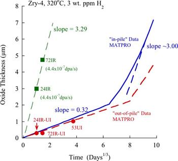
The corrosion kinetics of Zircaloy-4 in both in-pile and out-of-pile conditions has been studied extensively. Reference Bouineau, Bénier, Pêcheur, Thomazet, Ambard and Blat24–Reference Kido, Kanasugi, Sugano and Komatsu27 Figure 11 shows oxide thickness data from the in situ irradiation–corrosion experiment compared with in-pile data generated from MATPRO. Reference Allison, Berna, Chambers, Coryell, Davis, Hagrman, Hagrman, Hampton, Hohorst, Mason, McComas, McNeil, Miller, Olsen, Reymann and Siefken28 The unirradiated oxide growth rate of the reference sample was in good agreement with out-of-pile data. Reference Allison, Berna, Chambers, Coryell, Davis, Hagrman, Hagrman, Hampton, Hohorst, Mason, McComas, McNeil, Miller, Olsen, Reymann and Siefken28 The proton irradiation data is also shown, and the growth rate was about a factor of 10 higher than in the unirradiated case. Note that the growth rate was similar to that for in-pile behavior in the linear growth rate regime. In this regime, the oxide thickness was proportional to time, and hence to dose, furthermore, the oxide growth rate should be proportional to the dose rate. Therefore, equating the ratio of oxide growth rate to dose rate for protons, to that for neutrons yields a neutron dose rate of ∼4.4 × 10⁻⁸ dpa/s, in good agreement with the range of values in the literature; 3.2–6.5 × 10⁻⁸ dpa/s. Reference Iltis, Lefebvre and Lemaignan2,Reference Allen, Cole, Kenik, Rosinski, Grossbeck, Allen and Kumar29,Reference Van Duysen, Todeschini, Zacharie, Kumar, Gelles, Nanstad and Little30 This relationship suggested that oxidation under proton irradiation follows post-transition linear growth kinetics.
Plot of oxide thickness as a function of corrosion time for in-pile and out-of-pile data Reference Allison, Berna, Chambers, Coryell, Davis, Hagrman, Hagrman, Hampton, Hohorst, Mason, McComas, McNeil, Miller, Olsen, Reymann and Siefken28 and in situ proton irradiation–corrosion data.

Post-irradiation corrosion tests have demonstrated that irradiation damage to the metal prior to exposure in high-pressure high-temperature water has no effect on corrosion rate. Reference Woo, McDougall, Hutcheon, Urbanic, Griffiths, Coleman, Sabol and Moan8,Reference Cheng, Kruger, Adamson, Garde and Bradley9 Proton, neutron and electron irradiated zirconium metal and oxide have shown no evidence of enhanced diffusion of oxygen in the oxide during post-irradiation exposure experiments, Reference Woo, McDougall, Hutcheon, Urbanic, Griffiths, Coleman, Sabol and Moan8,Reference Iltis, Lefebvre and Lemaignan31,Reference Spitznagel, Fleischer and Choyke32 thus no enhancement on corrosion rate. However, the in situ irradiation–corrosion experiments showed a 10-fold enhancement of corrosion kinetics indicating that defect production during irradiation was driving the high corrosion rate. The enhanced corrosion rate was evidenced by the thicker oxide film formed on 24IR and 72IR, in the irradiated zone, compared with the areas that were exposed to water alone.
The unirradiated zones of the proton irradiated samples, 24IR-UI and 72IR-UI, showed no enhancement of corrosion kinetics. The corrosion kinetics of these regions were consistent with that found in separate autoclave exposures [Fig. 11]. Although these regions were exposed to water containing radiolysis products, the corrosion kinetics was unaffected.
The corrosion rate decreases with increasing oxide thickness, which indicates that the oxide provides protection to the underlying metal. In the early stages of Zr oxidation, the oxide is very thin; the rate-limiting step is believed to be the transport of oxidizing species (O2−) along oxide grain boundaries. The corrosion kinetics can be approximated by a cubic rate law, rather than a parabolic law predicted for a process controlled by bulk diffusion of oxygen through the oxide. As the oxide thickens, small equiaxed grains grow into columnar grains in a direction perpendicular to the compressive stress developed during corrosion. Thus, the cubic corrosion kinetics can also be evidence of the reduction of grain boundary area due to preferential growth of columnar grains. To maintain charge neutrality, electron migration in the opposite direction of oxygen ion transfer is required. Zirconia is an ionic crystal, there are few free electrons in the conduction band, and flow of electrons through the oxide can only be achieved by electrons hopping. Reference Cox7 Continuous oxide growth would require both the ion and electron currents to be balanced. However, as the oxide thickens, electron migration across the highly electrical resistive oxide is difficult and becomes the rate-limiting step. This electron migration process can affect the rate of surface reaction that produces oxygen ions (O2−), which further impedes the interfacial reaction at M/O interface. For there to be an enhancement of corrosion rate, the kinetics of the limiting process must be increased. Proton irradiation can increase the ion current through the high concentration of interstitials and vacancies created during irradiation. That the corrosion rate enhanced under proton irradiation indicates that, with the absence of a corresponding increase in electron transport, the ionic transport must have been limiting.
B. Oxide morphology
On non-irradiated samples 53UI and 24IR-UI, the oxide grew with strong preferential orientation relationship, leading to a strongly textured columnar-grained zirconia layer. This is consistent with other observations found on oxidized zirconium alloys. Reference Iltis, Lefebvre and Lemaignan2,33 The tightly aligned columnar oxide grains with very low lattice mismatch along the oxide growth direction are more protective than are equiaxed oxide grains. The oxide found on 24IR consisted mainly of equiaxed grains of m-ZrO2 containing intergranular defects and continuous paths through grain boundaries parallel to the M/O interface, as confirmed by electron diffraction analysis and HRTEM conducted on different locations throughout the oxide thickness. Raman spectra collected on the surface of 24IR in the irradiated zone also confirmed the presence of only m-ZrO2, which agrees well with diffraction data. This phase has also been found on in-reactor grown oxides. Reference Iltis, Lefebvre and Lemaignan2,Reference Lefebvre and Lemaignan34 The unique feature among oxides formed in reactor or under ion irradiation is the equiaxed grain structure. According to the observations made by Gong et al., Reference Gong, Zhang, Qiao, Xian, Ni, Li and Wang35 at the beginning of oxidation, monoclinic equiaxed grains are formed on the bare substrate. The corrosion rate is high because of the porous nature of this thin equiaxed grain oxide layer. As oxidation progresses, compressive stresses build up in the oxide layer and a columnar structure begins to grow to minimize surface energy. Iltis et al. Reference Iltis, Lefebvre and Lemaignan31 noted that nucleation and growth occur in two stages: first, is the nucleation of small nanocrystallites, preferentially tetragonal phase, randomly oriented grains; second, is crystallites with preferred orientation that develop a columnar structure. However, under irradiation, the crystallite nucleation and growth under normal circumstances is likely disrupted by the high concentration of defects at the M/O interface. This leads to an imbalance in the nucleation and growth process, giving rise to an increase of porosity and reduced cohesion between grains. The porous microstructure found on the 24IR sample provides evidence in support of this hypothesis. Isolated cracks observed at the M/O interface will act as obstacles to diffusion, slowing down the diffusion rate as described by Ni et al. Reference Ni, Lozano-Perez, Sykes, Smith and Grovenor36 Conversely, when these microcracks were interlinked to form a network of cracks, the corrosion rate can be accelerated due to forming easy migration path for oxidizing species along the interlinked cracks. Reference Iltis, Lefebvre and Lemaignan31
Regions with a higher concentration of columnar grains are expected to have a high resistivity against intergranular fracture since only a small fraction of the grain boundaries are parallel with the M/O interface. However, large lateral cracks were observed in the oxide layer on sample 53UI, parallel to the M/O interface. These cracks might be attributed to the large undulations found on pre-transition oxide layers. Parise et al. Reference Parise, Foerch and Cailletaud37 indicated that diffusion of oxygen in columnar grained zirconia through different grain boundaries could result in an inhomogeneous diffusion rate, which can give rise to the waviness of the M/O interface. This interfacial undulation is particularly pronounced in pre-transition oxides.
Due to a large Pilling–Bedworth ratio (∼1.56) for ZrO2 on Zr, Reference Pilling and Bedworth38 the oxide would be under compressive stress and metal substrate would be under tensile stress. However, since the M/O interface is undulated, the stress states along this wavy interface become complicated. Parise et al. Reference Parise, Sicardy and Cailletaud39 also showed that there are large local stresses in the oxide perpendicular to the interface, tensile stresses above the wave crests (the less oxide penetrated region where a metal substrate is protruding out into the oxide) and compressive stresses in regions between waves (the deeper oxide penetrated regions, where a oxide is protruding out into the metal). This model suggests that cracks can only form at the top of the metal crest, which is consistent with SEM observations found on Zircaloy-4 corroded in static autoclaves. Reference Bossis, Lelièvre, Barberis, Iltis, Lefebvre, Sabol and Moan40 These features were more pronounced in the 24IR oxide layer, where a large population of lateral crescent-shaped cracks was found throughout the oxide thickness as shown in Fig. 5(c).
Crescent-shaped cracks formed adjacent to SPPs are usually associated with delayed oxidation of the precipitate, when the expansion of the oxide surrounding the SPP exceeds the maximum tensile stresses that the precipitate/oxide interface can bear. Reference Proff, Abolhassani and Lemaignan41 The reason for the formation of these crescent cracks, located on the side facing the outer oxide surface as observed in both irradiated and unirradiated oxide, can be explained by a change in interfacial energy together with the tensile load generated by the outwards volume expansion during oxide growth. As the surrounding matrix becomes oxidized the volume around the SPP starts to expand, generating a tensile stress at the precipitate/oxide interface. Due to the general lack of adhesion of the metal/ceramic interface, it is prone to develop a crack to accommodate the tensile strains. This type of crack adjacent to the SPPs would also add to the already porous microstructure of 24IR oxide and provide additional pathways for the oxidizing species to access the M/O interface.
C. SPP oxidation and stability under irradiation
The microstructural and chemical changes of the SPP as they are incorporated into the oxide layer without irradiation has been studied extensively. Reference Garzarolli, Seidel, Tricot, Gros, Eucken and Garde42,Reference Pêcheur, Lefebvre, Motta, Lemaignan and Wadier43 The main finding is that oxidation of the SPPs is delayed compared with the surrounding metal matrix, such that it occurs only after being consumed by the oxidation front by several hundred nanometers to 1 µm from the M/O interface. Beyond 1 µm, the SPPs are fully oxidized and no longer subject to further structural or chemical changes. When it is finally oxidized, it gives rise to the formation of nanocrystallites of tetragonal/cubic zirconia, and it is usually accompanied with rejection of Fe at the precipitate/oxide interface. Reference Iltis, Lefebvre and Lemaignan2,Reference Pêcheur, Lefebvre, Motta, Lemaignan, Charquet, Garde and Bradley15
Absent of irradiation, a protective tetragonal phase (t-ZrO2) forms at the M/O interface stabilized by large compressive stresses associated with oxide growth and containing almost no Fe. Micrometers away from the M/O interface, the oxide can be doped significantly by rejected Fe from SPPs. Since Fe stabilizes t-ZrO2, the allotropic transformation from the tetragonal to monoclinic phase can be locally postponed. Reference Lefebvre and Lemaignan34 However, no tetragonal phase was found in either unirradiated sample 53UI or the unirradiated region of 24IR.
SPP amorphization alone does not seem to affect corrosion behavior. Pêcheur et al. Reference Pêcheur, Lefebvre, Motta, Lemaignan, Charquet, Garde and Bradley15 showed that there is no change in oxidation rate when comparing non-irradiated reference material with a pre-irradiated sample, even at a neutron damage level that causes complete SPP amorphization. However, dissolution of both amorphous and crystalline SPPs does influence corrosion. This dissolution process leads to significant enrichment of alloying element (e.g., Fe, Cr in the case of Zircaloy-4) in the surrounding metal matrix.
SPPs observed in the neutron-irradiated Zr were partially or completely amorphized, some smaller SPPs were even dissolved in the metal under irradiation. Reference Iltis, Lefebvre and Lemaignan2 Fe rejection from SPP also occurred during amorphization, Iltis et al. Reference Iltis, Lefebvre and Lemaignan2 found that the Fe/Cr ratio decreased from 1.7 to 0.2 prior to incorporation of metallic SPPs into the oxide matrix under neutron irradiation. Under thermal conditions, Fe shows higher diffusivity than Cr, both in alpha-Zr and in metallic SPPs. Hood and Schultz Reference Hood, Schultz, Van Swam and Eucken44 determined that the diffusion coefficient of Fe is two orders of magnitude higher than that of Cr in alpha-Zr. Baek and Jeong Reference Baek and Jeong45 confirmed that Fe depleted faster than did Cr in SPPs, which implied that the diffusivity of Fe was faster than that of Cr in Zr(Cr, Fe)2.
For the 24-h proton irradiation–corrosion experiment, the SPPs found in the metal were unchanged, no amorphization or dissolution was observed, which is not surprising given the short duration and total dose. However, SPP oxidation occurred for those SPPs consumed by the growing oxide front. In this case, we measured preferential Cr from the SPP and into the surrounding oxide. Composition redistribution occurred during the oxidation phase, and it is likely that it occurred along the grain boundaries, as grain boundary diffusion is believed to be the dominant mechanism in ionic nanocrystallite materials. Reference Murty46 However, due to the lack of data on Cr and Fe diffusion in nanocrystalline zirconia, the role of radiation on diffusion in the oxide phase cannot be determined.
V. CONCLUSIONS
The following conclusions have been obtained:
-
(1) Corrosion kinetics of Zircaloy-4 was strongly affected by proton irradiation. Oxide formed under irradiation is an order of magnitude thicker than that without irradiation.
-
(2) Corrosion kinetics of the in situ proton irradiation–corrosion experiment matched that of in-pile kinetics in the post-transition regime; the pre-transition regime was absent.
-
(3) The morphology of the oxide formed during proton irradiation was similar to the oxide formed under neutron irradiation. The irradiated oxide consisted of equiaxed m-ZrO2, with a preferential orientation of the grains. A large volume fraction of cracks and fine pores were present throughout the thickness of the oxide.
-
(4) SPPs underwent accelerated oxidation after being consumed by the oxide.
-
(5) Unirradiated areas of the proton-irradiated samples exhibited corrosion kinetics that were in good agreement with out-of-pile test results, indicating that water radiolysis had negligible effects on the corrosion rate of zirconium.
ACKNOWLEDGMENT
This research was supported by the DOE-NEUP, Grant No. DE-AC07-05ID14517, Contract No. 8610-BVW-4300243004, and Consortium for Advanced Simulation of Light Water Reactors (CASL) under U.S. Department of Energy Contract No. DE-AC05-00OR22725.