I. INTRODUCTION
The study of irradiation-produced defects and microstructure by transmission electron microscopy (TEM) has a long history dating back to the late 1950s and early 1960s. A remarkable aspect of this history is the fact that the most useful TEM techniques have changed rather little over this time. Diffraction contrast has proven better suited to imaging irradiation defects than the more recent high-resolution methods. The central reason for this is that diffraction contrast, especially as practiced using weakly diffracting beams, is more suited to resolving defect structures by imaging strong contrast from the distorted lattice near the defect and suppressing the contrast from the surrounding matrix. Whereas images produced using the major high-resolution techniques are dominated by the undistorted atomic structure and the defect structure is usually observed as a weak perturbation on the perfect atomic structure. Few radiation-damage defects satisfy the condition for a successful structural determination by high-resolution electron microscopy (HREM), that is, the specimen may be necessarily thin (<20 nm) and oriented such that columns of atoms passing through or close to the defect line up in projection along the beam direction.
With renewed interest in nuclear power and the need for new materials to improve reactor lifetime costs by resisting material property degradation due to the bombardment by neutrons over long periods of time, the study of the response of new alloys to irradiation has again found strong interest. The fundamental TEM techniques used to analyze radiation damage are well established and are described in detail not just in the literature (e.g., the review by Jenkins Reference Jenkins1 ) but also in many textbooks (e.g., Refs. Reference Jenkins, Kirk and Cantor2–Reference Williams and Carter4). In this paper, we will place an emphasis on experimental considerations and protocols when applying the fundamental techniques which have not hitherto been included in textbooks. It is hoped that the experimental experiences and suggestions discussed in this paper will contribute to more successful TEM work on the advanced alloys for future use in the next generation of nuclear power reactors.
II. IRRADIATIONS AND SAMPLE PREPARATION CONSIDERATIONS
Before considering various TEM methods for characterizing and quantifying irradiation induced defects and microstructure, it is helpful to understand several different irradiation conditions which give rise to the defects and some of the ways samples are prepared to examine these defects by TEM. The most important irradiation type involves neutrons, usually from a degraded fission energy spectrum typically found in structural components in or near nuclear reactor cores. Such neutrons produce atomic level damage through their collisions with the atoms of the material, and that damage can result in dimensional and mechanical property changes that limit the lifetime of the reactor. As the cross-section for collisions between neutrons and atoms in the metal alloy is quite small, the resulting damage is homogeneous throughout bulk samples, and a TEM investigation can be performed on material from any part of the sample. However, studies designed to understand this damage, especially at long reactor lifetimes are expensive, take several years and involve the handling of active materials. In such experiments, control of various material and irradiation parameters is very limited. Thus, ion irradiations have long been used to study similar defects produced in a more controlled and timely fashion.
Several different ion irradiation conditions have been used to study fundamental aspects of damage characteristics. Ions have much larger collision cross-sections than neutrons, and so the damage level varies strongly along the incident ion path. In one commonly used method of ion irradiation, a high-energy ion beam is incident on the surface of a bulk specimen and eventually is stopped at the end-of-range in thick material. In this case, a TEM sample is often prepared at a certain depth of ion penetration where the ion damage can be clearly defined, and the distance from the incident surface is sufficient to preclude an influence of that surface on the damage. Sample preparation to accomplish this involves controlled thinning to a predetermined depth from the incident surface, usually by electro-chemical means and back-thinning until perforation. There is often considerable uncertainty in the depth examined by TEM using this method. Reference Yao, Xu, Jenkins and Kirk5 Another now common sample preparation technique for this type of ion irradiation uses a focused ion beam (FIB) miller that can make (by sputter-erosion) and extract a thin foil to be viewed in cross-section, perpendicular to the original ion beam (a review of this technique is in Ref. Reference Giannuzzi and Stevie6). This has the obvious advantage that the depth distribution of the damage is viewed directly. However, great care must be taken to minimize the material damage produced by the FIB itself, which is mainly located in the near surface region of the thin section. Electro-chemical “flash” polishing has recently been used to selectively remove the immediate surface layers where the FIB damage and deposition of the milling ion are most significant. Reference Prokhodtseva, DeCamps and Schaeublin7
A second common type of ion irradiation is that of material already thinned (100 nm) for TEM. Two different types of experiment are carried out. In the first, the irradiating ion is chosen to be the same as the sample material or a major constituent in an alloy and the ion energy is selected (say 200 keV) to make the end of range within the thin foil, perhaps near the foil center. The incident ions in this case mimic primary knock-ons in neutron irradiation. In the second type of experiment, the ion energy is sufficiently high (say 1 MeV) that most ions pass completely through the foil. The first condition produces damage from the incident surface to a peak damage near foil center; the second condition produces damage more homogeneously through the entire foil thickness. These two ion irradiation conditions are typically used for in situ experiments such as performed at the IVEM-Tandem Facility 8 at Argonne National Laboratory. They have the advantage that the damage is imaged dynamically in real time as it is produced and evolved with dose. However, unlike neutron or ion irradiations of bulk samples, damage evolution in thin-foil irradiations may be influenced strongly by the two foil surfaces. The effect of nearby surfaces must be studied and understood if bulk behavior is to be predicted.
A less common type of ion irradiation, which has been the subject of TEM studies of some materials especially the oxide superconductors, uses heavy ions in the GeV range. This irradiation condition will see increased use to simulate fission fragment damage in nuclear fuels. These very high-energy ions have ranges of several tens of micrometer. The damage produced varies strongly along the ion path. The energy loss along the initial length of the ion path is mostly due to inelastic losses to the electron system in the material and results typically in a column of amorphization in highly resistive metals (as in the oxide superconductor YBaCuO Reference Wheeler, Kirk, Marwick, Civale and Holtzberg9 ) or insulators. The energy loss at the end of range is dominated by elastic atom recoils and resultant collision cascades of atoms. TEM studies require careful control of the depth of the thin section, but over a larger depth of penetration than is conveniently achieved in cross-section by the FIB lift-out technique.
It cannot be overemphasized that a successful analysis of defect densities, sizes, and structures requires samples of the highest possible quality, such that preparation artifacts are minimized. This may require a considerable investment of time and effort in optimizing the electro-polishing technique, Reference Yao, Xu, Jenkins and Kirk5 or by careful control of the FIB technique.
Particular difficulties in sample preparation can be encountered in experiments, involving ferromagnetic or highly radioactive (neutron irradiated) materials, sometimes in the same sample. In electro-polishing of both magnetic and radioactive samples, the mass of the final TEM specimens should be minimized. Starting discs should be as thin as possible, usually near 50 μm. FIB produces tiny samples which is a clear advantage for both magnetic and active materials.
III. IMAGING CONDITIONS FOR CHARACTERIZING IRRADIATION DEFECTS
We begin with TEM of samples with irradiation defects produced by lower ion or neutron doses, such that individual small dislocation loops are found at densities that allow for quantitative analysis.
To count, size, and characterize the structure of small defects (1–5 nm), imaging with controlled diffraction conditions is necessary. The sample is tilted to achieve the orientation with respect to the incident electron beam to reach the desired diffraction condition. This is not very difficult in single-crystals or polycrystals with grains of size >0.5 μm, where controlled tilting can be done by the observation of the Kikuchi pattern in a diffraction mode. However, tilting to a controlled diffraction condition will often prove difficult in smaller-grained materials, especially if in a magnetic alloy. We recommend in this case making small tilt increments in the image mode, to be able to chase and not lose the desired grain and the beam. Iteration between image and diffraction modes is tedious but necessary. Dark-field images can be particularly useful in tilting to excite particular reflections. It is useful to choose grains with a minimum of pre-existing dislocation structure prior to irradiation. This is easily done for in situ ion irradiation experiments, but must involve some experience in the unirradiated alloy in ex situ ion and neutron irradiation experiments. Grain selection is also based on crystallographic orientation, such that a suitable major pole is located within a reasonable tilt from the foil normal. Then, accessible diffraction vectors for the determination of Burgers vectors are often available.
Recent interest in irradiation experiments on small-grained materials (approaching so-called nanograined character) introduces the question of what are the limits of that which can be done for imaging defects in such materials under controlled diffraction conditions. In our experience, using a microscope with a LaB6 filament and typical beam spot size for image work, control of diffraction condition, and sample orientation is possible with care down to a grain size of perhaps 0.3 μm. Of course, a microscope with smaller spot size, as with a field emission gun (FEG), will produce individual diffraction patterns at the smaller grain sizes. However, in actual nanograined material with grains of sizes <0.1 μm (100 nm), one may be forced to arbitrarily tilt until an image of dislocation structure is produced under some unknown weakly diffracting conditions. Then at least, experiments on defect kinetics and sizes may be performed under irradiation in situ, with defect structure and accurate density measurements very limited.
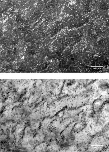
The two most useful diffraction conditions for imaging small dislocation loops and associated defect structures for quantitative analysis are weak-beam dark-field and bright-field kinematic. The basic instruction for achieving these diffraction conditions can be found in most TEM textbooks. Reference Jenkins, Kirk and Cantor2–Reference Williams and Carter4 When possible, micrographs should be recorded under both conditions in the same area. The presence of defect images in both micrographs can then be used to resolve ambiguities due to differences in background image or surface noise. The bright-field kinematic condition is also often more useful at high dose for best revealing extended dislocation structures (see Fig. 1). Best images require careful microscope alignment and image correction: illumination centering, rotation centering, aperture centering, focus, and astigmatism correction, all in that order. Choose an objective aperture size about twice the diameter of the beam spot with beam focus/intensity set as for an imaging illumination. This avoids a scattering background from the aperture edge if too small and includes some inelastic scattering by the sample that can contribute usefully to defect contrast. Choose an exposure time of 1–2 s for both kinematical bright-field and weak-beam images if possible, to reduce microscope noise while minimizing image drift.
Weak-beam dark-field (WBDF), g = 110 (g, 5g; upper panel) and bright-field kinematic (BFK) (lower panel) pair of the same area of Mo irradiated to 2 dpa by 1 MeV Kr++ at 80 °C, illustrating a high density of defects and difficult background in WBDF, and better resolution of extended defect structure in BFK.

IV. COUNTING AND SIZING DEFECTS
In general, weak-beam dark-field diffraction conditions should be used for defect counting and sizing. There are, however, limitations to the accuracy within a single imaging condition since the defect image contrast varies with loop depth, foil thickness, and deviation parameter as shown in the image simulations of Zhou et al. Reference Zhou, Jenkins, Dudarev, Sutton and Kirk10 To make an accurate count of areal density, it is recommended that at least three slightly varying weak-beam conditions be used, with differing deviation parameters. In the usual notation, where (g, n g) refers to a weak-beam image taken in a reflection g with the bright Kikuchi line passing through n g (see Ref. Reference Jenkins, Kirk and Cantor2, p. 8 or Ref. Reference Williams and Carter4, Vol. III, p. 424 for details), these weak-beam images should differ in n by about 0.25 in a range within n = 4–6. Several images will largely overcome the limitation that within a single image some defects may show weak or absent contrast (not to be mistaken for g·b = 0 invisibility). Reference Jenkins, Kirk and Fukushima11
Note that the Zhou simulations were performed for g = 200 in Cu at an electron energy of 100 kV. The value of n in the (g, ng) notation to achieve the same deviation from Bragg, s, for another material, g and kV will differ from the Zhou parameters. Therefore, it is wise to experimentally investigate a range of n to find the best weak-beam imaging conditions for the experiment and to determine the s and n values in the particular situation to compare with Zhou.
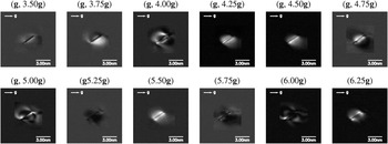
Sizing of any individual defect is best taken from the largest image from a weak beam series (e.g., three images with n and n ± 0.25) of that defect, and in the direction of maximum extent of that defect image contrast. The simulations of Zhou (Fig. 2) show that this image most closely corresponds to the actual loop diameter under sufficiently weak diffraction conditions (n > 5 in his case). To avoid some image complexity, it is best to not excite exactly any systematic reflection (i.e., n should not be integral) and to avoid exciting strongly any nonsystematic reflections in the diffraction pattern.
Simulated weak-beam images of an edge-on loop of diameter 3 nm with Burgers vector b = 1/3[1-11] for various weak-beam diffraction conditions from (g, 3.50g) to (g, 6.25g) with g = 002. The foil thickness is 60 nm and the loop depth is 30 nm. From Zhou et al. Reference Zhou, Jenkins, Dudarev, Sutton and Kirk10

The distribution of maximum loop image sizes, obtained from the weak-beam series, will have a variation with loop depth and foil thickness of about ±20%, about the average maximum image size. The average is close to the true average loop size. Thus, a measurement of true average loop size is easily performed using the data from the same weak-beam series that is used to make an accurate defect density measurement. However, this distribution of maximum image sizes will not be a distribution of true loop sizes, but instead a convolution of distributions of true loop sizes with variations due to loop depth and foil thickness. Reference Zhou, Jenkins, Dudarev, Sutton and Kirk10
Average of all image sizes in one micrograph is not accurate, but biased toward smaller than the true loop size average due to the inclusion of some small loops with significant smaller image sizes at the one n value (see Fig. 2). However, if the distribution of image sizes includes few of size <5 nm, the average image size from a single micrograph will be close to the true average loop size. The size distribution will still be broadened by the variations due to loop depth and foil thickness.
Defect image visibility can be affected by sample material, surface orientation, polishing conditions, contamination or oxide formation, and imaging diffraction conditions. Difficulty with any of these conditions can produce an image background out of which defect identification can be difficult, leading to problems in counting especially of very small defects. Generally, it is best to look at the background variations in size, shape, and intensity and to identify defect images that appear significantly different. Usually, too low or too high a magnification is not helpful. The simplest counting scheme is one with only two levels of confidence. Those contrast shapes, which correspond with strong confidence to loops, are then counted as “probables”, and those images with some doubt are counted as “possibles”. Then it is reasonable, even conservative, to quote an areal density as all the probables plus one half the possibles with uncertainty of plus or minus one half the possibles. An example of defect images and a difficult background out of which to count defects is shown in Fig. 1.
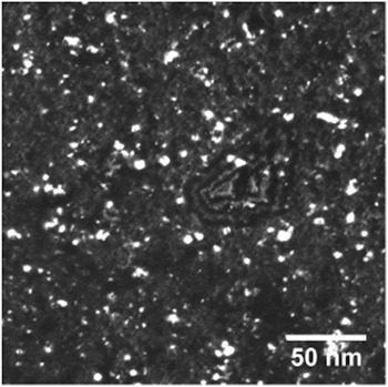
If the image background is sufficiently smooth and relatively featureless (Fig. 3), it may be possible to use digital image processing tools such as those found in ImageJ for semiautomated defect counting and sizing. A loop is defined and counted by the software when the local contrast intensity exceeds the measured fluctuation in background intensity in the same micrograph. An uncertainty in the count can be defined to be the difference in counts taken within the fluctuation in background about a threshold value of loop contrast. Using the same software, image size distributions can also be measured. More complete descriptions of these methods, as applied to small loops in W, can be found in the DPhil thesis of Yi. Reference Yi12 It should be mentioned that while this digital counting method worked well in the high quality pure W and W-alloy samples, it may be unlikely to work as well in samples of more complex compositions (e.g., ODS-steels) where image backgrounds can be expected to have higher fluctuations. In this case, manual counting methods as described in the previous paragraph will need to be used.
Sample image for digital processing of density and sizes. Damage microstructure of W–5Re irradiated with 2 MeV W+ ions at 800 °C and recorded under weak-beam dark-field, g = 200, 3-4g.

Two further problems often arise in defect counting. One is that the low size limit is not a single size value. The low size limit is often defined by the smallest resolved defects, often at an image diameter of 1 nm. However, it is likely that some loops above this low size limit are not resolved due to background fluctuations and other factors. Thus, a varying fraction of defects in low-size bins is not resolved and therefore uncounted. The safest way to avoid this problem is to define a defect count as those with diameters at and above the peak in the size distribution, when that peak (typically at 3–4 nm) is defined by a loss of resolution of small defects. A defect count defined in this way is unlikely to miss many defects due to poor resolution. Another counting problem arises when defect images overlap in the projection through the foil thickness at higher doses. One way to judge if this is a problem in bulk-irradiated samples is to measure and plot the defect areal density as a function of foil thickness in a wedged foil. Deviation from linear behavior would indicate a possible image overlap problem.
V. DEFECT STRUCTURE DETERMINATION
To characterize the dislocation loop structure completely, one needs to determine the Burgers vectors, habit planes, and interstitial or vacancy nature of individual loops. A complete characterization requires both an excellent sample and rather careful and extensive contrast experiments with different diffraction conditions in the same area of foil. A decision must be made whether the sample quality is adequate, and if the need for all this information is great enough to pursue. A compromise to obtain less detailed structural information may be more pragmatic. In either case, we will not go through the details of TEM methods here, as they can be found in all the general references. Reference Jenkins, Kirk and Cantor2,Reference Williams and Carter4,Reference Hirsch, Howie, Nicholson, Pashley and Whelan13 A full analysis by Yi Reference Yi12 in an (001) W grain required loop contrast behavior to be determined in eight independent diffraction vectors (from a total of 3 poles) to distinguish all variants of ½<111>, ½<110>, and <100> Burgers vectors as predicted by the Eyre–Bullough mechanism for body-centered cubic (bcc) metals. Reference Eyre and Bullough14 The same type of analysis by Yao et al. Reference Yao, Hernandez-Mayoral, Jenkins and Kirk15 in a Fe grain oriented near (111) required 11 diffraction vectors. Determination of the interstitial or vacancy nature of loops is particularly problematic. The inside–outside contrast method generally requires loops to be of size >5 nm. Smaller loops cannot be analyzed this way. The black–white contrast method which is based on dynamic images can work for loops in a size range 2–5 nm, but requires a measurement of loop depth in the foil. Tomographic data and image simulations may result in a successful nature determination with this method, but again, a substantial effort must be made, and the method only works if the loops lie close to the surface and so show black–white contrast. Perhaps, the most convincing determination of the nature of very small loops has been made in in situ thin-foil irradiations, where small mobile loops have been observed to coalesce into resolvable large loops whose nature could be found by inside–outside contrast. Reference Yao, Hernandez-Mayoral, Jenkins and Kirk15
The methods of loop characterization discussed here all require one-to-one correlation of loop contrasts from one micrograph to various others. If such procedures were not possible (e.g., in high dose irradiations) or we were merely interested in the relative fractions of loops with different morphologies (e.g., the relative fraction of ½<111> versus <100> loops in a bcc specimen, without regard to different variants of each type), a statistical approach can be applied. The method relies on the equal production of each symmetrically equivalent Burgers vector variant and extracts the relative fractions of each loop geometry from their contributions to loop number densities when different g vectors are excited (assuming invisibility of loops if g·b = 0). Surface effects must also be taken into account. Details of this method are described in Prokhodtseva et al. Reference Prokhodtseva, DeCamps, Raman and Schaeublin16
In oxide dispersion strengthened (ODS) and other complex alloys, it may be necessary to separate similar images of small precipitates from dislocation loops. If the precipitates are coherent and have sufficient volume, the selection of their dark-field images using precipitate reflections may be used to distinguish them from the purely structural defects such as dislocation loops. If the electron density of the precipitate is sufficiently different from the matrix (e.g., ODS precipitates), Fresnel fringes from defocused images may distinguish them from loops.
In alloys taken to higher doses, extended dislocation structures often form. Such linear structures are often more apparent in bright-field kinematic images, especially when large numbers of loops are also present (Fig. 1). The quantification of such damage structures is perhaps a problem. One suggestion is to determine the dislocation density. The total length of dislocation line and the foil thickness are measured in a chosen area. This line length can also include the circumference of small loops resolved only as a single contrast feature (black or white dots).
VI. IMAGING, COUNTING, AND SIZING SMALL VOIDS
Void images are often produced using the defocus method in a standard TEM without scanning. Reference Jenkins, Kirk and Cantor2 Another common method uses STEM in both bright-field and annular dark-field to detect and measure void densities and sizes. A new study goes into good detail on this method and its application. Reference Getto, Jiao, Monterrosa, Sun and Was17 It has the advantage of slightly better resolution and discrimination between voids and most precipitates and surface features.
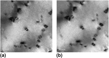
Here, we describe a few considerations to be borne in mind when using these methods. First, preparation of cross-section specimens using FIB may well introduce near-surface voids and surface features, which could be mistaken for voids produced by neutron or ion irradiation in either defocus or STEM methods. Unirradiated specimens prepared by the same method should be examined to check this. Plan view samples are best produced by electro-polishing. However, even in this case, imaging by the defocus method may result in Fresnel fringe contrast from precipitates with an electron density sufficiently different from the matrix. ODS particles may be a case in point, as investigated recently in Ref. Reference Parish and Miller18. In in situ irradiations such as those carried out in the IVEM, ODS particles in the area of interest can be identified prior to ion irradiation, and the same area can be followed during the ion irradiation, easily distinguishing existing ODS particles from irradiation produced voids. Surface features may also give rise to void-like contrast. Surface craters produced by dense near-surface cascades are unlikely from self-ion or Kr ion impacts in metals with mass near that of Fe, but are more likely in heavier materials. Possible voids and surface craters in W produced by 150 keV W+ irradiation at 800 °C are seen in Fig. 4. Surface craters can be distinguished by stereomicroscopy.
Out-of-focus images of voids in ultra-high purity (UHP)-W irradiated with 150 keV W+ ions at 800 °C, to a dose of 1.0 dpa: (a) Δf = −896 nm, best contrast is achieved and the voids appear as white dots surrounded by dark fringes; and (b) Δf = +896 nm, voids appear as dark dots surrounded by bright fringes.

VII. MEASURING FOIL THICKNESS IN THE MICROSCOPE
Finally, determination of defect volume densities requires the measurement of foil thicknesses in the areas of interest. We consider here some possible methods, some of which can be applied only under certain circumstances. The most straightforward involves thickness fringes seen in grains that extend to the foil edge with a not-too-steep wedge angle and no bending. Both dynamical and weak-beam conditions may be used, although the diffraction condition must be well established. In the dynamical 2-beam case, extinction distances may be determined from simulations. In weak-beam diffracting conditions, the deviation parameter must be measured from the diffraction and Kikuchi line pattern to an accuracy in n of about 0.25 in the (g, n g) notation, giving the effective extinction distance. The method allows the local foil thickness to be estimated to about 20% accuracy.
In alloys with grains of size >0.5 μm, but not extending to the hole, a tilting method may be used to measure the grain thickness. Reference Hengstler-Eger, Baldo, Beck, Dorner, Ertl, Hoffmann, Hugenschmidt, Kirk, Petry, Pikart and Rempel19 A grain with a fairly straight grain or twin boundary along or close to the direction of the main tilt axis can be used to image the projected width of the boundary over a range of tilt from about −40° to +40°. The projected boundary width at different tilt angles can then be used to calculate the foil thickness to an accuracy approaching 10%. This technique can probably be performed successfully only in nonmagnetic alloys. A related tilting technique uses a focused electron-beam to produce a contamination spot simultaneously on both foil surfaces. By tilting through a known angle and measuring the projected distance between contamination spots on the two surfaces, the thickness can be calculated. This would work best with the small focused beam from a FEG source.
Two further established techniques to measure local foil thickness are in principle applicable in a greater range of conditions. One uses the electron energy loss spectroscopy (EELS) log-ratio technique with an accuracy of about 10%, and the other is a CBED technique with an accuracy near 5%. Both are well discussed in many standard textbooks. One possible drawback with the EELS method is the need to estimate the total inelastic mean free path in an alloy. A likely problem with CBED is the loss of good crystallinity with irradiation damage resulting in a smearing out of the Kossel–Moellenstedt fringes. Thus, CBED may only be an effective technique before irradiation (appropriate in an IVEM in situ experiment), or samples irradiated to a sufficiently low dose.
VIII. SUMMARY
We have briefly presented different irradiation and sample conditions commonly used to study defects in materials introduced by ion and neutron irradiations. Advantages and disadvantages for the different irradiation and sample methods were presented.
Weak-beam dark-field and bright-field kinematic imaging diffraction conditions are generally recommended even in small-grained (>0.5 μm) materials. However, patience may be required to establish known diffraction conditions in small-grained materials, especially if magnetic. But careful technique can succeed.
Protocols for counting and sizing small (1–5 nm) dislocation loops are discussed. Recommendations based on the simulation work of Zhou are made. Also discussed rather briefly are suggestions for Burgers vector and nature determinations, but the detail is left to be found in the textbooks. Counting and sizing small voids using the defocus method are included, and finally determining foil thickness for defect volume density measurements is outlined.
ACKNOWLEDGMENTS
MK acknowledges support by the DOE Office of Nuclear Energy, operated under Contract No. DE-AC02-06CH11357 by UChicago Argonne, LLC. XY is supported in part by the UK EPSRC, via the program grant ‘Materials for Fusion and Fission Power’, EP/H018921/1.