INTRODUCTION
Since the experiment conducted by Nation (Reference Nation1970), high power microwave (HPM) source device is widely used in a variety of fields from civilian to military (Swegle et al., Reference Swegle and Benford1998; Parker et al., Reference Parker, Abrams, Danly and Levush2002; Thumm, Reference Thumm2009). As HPM technologies mature gradually, great effort has been made on enhancing the output power and the conversion efficiency of the narrow-band HPM devices (Chen et al., Reference Chen, Liu, Huang, Song, Fan and Wang2002; El'chaninov et al., Reference El'chaninov, Korovin, Rostova, Pegel, Mesyats, Rukin, Shpak, Yalandin and Ginzburg2003; Kim et al., Reference Kim, Jung, Min, Shin and Park2007; Li, Reference Li2008b; Totmeninov et al., Reference Totmeninov, Kitsanov and Vykhodtsev2011). However, recent researches on HPM effects indicates that the microwave pulse consisting of several frequency components is likely to decrease the injury threshold of the electronic devices and cause serious damage (DNA-TR-89-31-VI, 1989; Fang et al., Reference Fang, Liu, Li, Wang and Huang1999), especially when the beating frequency is close to the inherent frequency of the electronic devices (Giri et al., Reference Giri and Tesche2004). As a result, the development of the beating-wave generator has attracted more and more attention (Li et al., Reference Li, Shu, Zhang, Yang and Yuan2010; Wang et al., Reference Wang, Qin, Chen, Wen and Jin2011; Tang et al., Reference Tang, Meng, Li, Zheng, Wang and Zhang2013).
The conventional approach to obtain the beating wave of HPM pulse is the synchronous operation of an array of HPM source devices. However, the operation of the several independent HPM generators may cause some difficulties in practical application such as establishment of several expensive pulsed solenoid or superconducting guide magnet systems for each generator (Li et al., Reference Li, Shu, Zhang, Yang and Yuan2010), modification of the accelerator into multiple channels (El'chaninov et al., Reference El'chaninov, Klimova, Koval'chuk, Mesyats, Pegel, Romanchenko, Rostova, Sharypov and Yalandin2011), accurately synchronous trigger (Cruz et al., Reference Cruz, Hoff, Pengvanich, Lau, Gilgenbach and Luginsland2009; Teng et al., Reference Teng, Song, Sun, Xiao, Song, Zhang, Zhang, Zhang, Zhang, Li and Fang2012), and so on. Besides, the power capacity of the dielectric window in the diplexer (Chang et al., Reference Chang, Liu, Fang, Tang, Huang, Chen and Zhang2010; Li et al., Reference Li, Yuan, Zhang, Shu and Zhang2008a) may result in much trouble. Advanced research has proposed another method to produce beating wave of HPM pulse based on the coaxial relativistic backward wave oscillator (CRBWO) as shown in Figure 1 (Teng et al., Reference Teng, Xiao, Liu, Tang, Chen and Shao2010; Reference Teng, Xiao, Song, Jun, Chen and Shao2011a; Reference Teng, Xiao, Song, Sun, Chen and Shao2011b). Wang introduces an idea of azimuthally dividing the coaxial slow wave structure (SWS) of CRBWO into two parts to realize a bi-frequency oscillation (Wang et al., Reference Wang, Qin, Chen, Wen and Jin2011). The microwave pulse of 9.7 and 9.87 GHz is generated with the average power of 0.66 GW and the conversion efficiency 15.8% under the diode voltage 520 kV and current 8 kA in particle in cell (PIC) simulation. Later a new type of CRBWO with the sectioned coaxial SWS is put forward (Tang et al., Reference Tang, Meng, Li, Zheng, Wang and Zhang2013). PIC simulation indicates that the microwave pulse consisting of double frequency components of 8.1 and 9.9 GHz is generated when the diode voltage and beam are 510 and 9.03 kA. The conversion efficiency is promoted up to 21.7% while the average microwave power is 1.0 GW. Though these initial researches on CRBWO have provided feasible approaches to produce the beating wave of HPM pulse, the azimuthal or axial dividing of the coaxial SWS make the further increasing of the output power and the conversion efficiency considerably difficult. Because one annular electron beam traveling through the two divided SWSs with different resonant frequencies, electromagnetic field with different frequencies may compete with each other. Such competition is likely to degrade the conversion efficiency of the wave-beam or even terminate the microwave generation.
(Color online) Structure of CRBWO. (1) guide magnet solenoid; (2) annular cathode; (3) anode foil; (4) double rippled walls; (5) inner conductor; (6) electron collector; (7) output waveguide.

In order to attain the beating wave of HPM pulse efficiently and practically, our research aims to develop a compact beating-wave generator from CRBWO according to its special structure and physical characteristics. CRBWO is a new type of HPM source device remarked by its high conversion efficiency (Ge et al., Reference Ge, Zhong, Qian, Zhang, Liu, Gao, Yuan and He.2010a; Teng et al., Reference Teng, Chen, Shao, Sun, Song, Xiao and Du2013a), compact structure (Gao et al., Reference Gao, Qian and Ge2011), and frequency tunability (Ge et al., Reference Ge, Zhong, Qian, Zhang, Gao, Jin, Fan and Yang.2010b). The coaxial SWS with double rippled walls are supposed to be able to modulate and interact with the double annular beams efficiently (Teng et al., Reference Teng, Sun, Chen and Shao2013b). In order to make full use of the inner conductor, it can be modified by installing the hollow SWS complemented into it with a reflector and an abstracting cavity and serve as the inner RBWO. This provides the possibility for the operation of the diode structure with the multiple coaxial annular cathodes driven by one accelerator, which provides the pulsed power (Kovalchuk et al., Reference Kovalchuk, Kharlou, Zherlitsyn, Kumpjak, Tsoy, Vizir and Smorudov2009; Liu et al., Reference Liu, Yin, Ge, Zhan, Chen, Feng, Shu, Zhang and Wang2007). Besides, the electromagnetic field of the quasi-TEM mode generated by CRBWO can be easily converted into TM01 mode in the cylindrical waveguide in experiments (Teng et al., Reference Teng, Xiao, Song, Jun, Chen and Shao2011a). Inspired by the distinguishing structure and the physical characteristics of CRBWO, the multi-coaxial relativistic backward wave oscillator (M-CRBWO) that produce beating wave of narrow-band HPM pulse driven by one accelerator is developed as shown in Figure 2. In the diode structure as shown in the blue pane of Figure 2, one inner cathode feeds the annular beam into the inner RBWO while the two outer cathodes feed the outer CRBWO. The coaxial reflector consisting of two cavities located on the inner and outer conductors, which can pre-modulate two electron beams respectively, is employed to enhance the conversion efficiency of the wave-beam interaction in the outer CRBWO (Teng et al., Reference Teng, Liu, Shao and Tang2009). The fluting electron collector prevents the expansion of the plasma generated by the direct bombardment of the electron beam (Teng et al., Reference Teng, Chen, Shao, Sun, Song, Xiao and Du2013a). In Figure 3, the coaxial transmission supporter, which fixes the inner RBWO into the outer CRBWO and connects them equi-potentially by the six connecting plates, is able to convert TEM mode in the coaxial waveguide into TM01 mode in the cylindrical one with little reflection for the sake of the incoherent combination and output of the generations of the inner RBWO and outer CRBWO.
(Color online) Configuration of M-CRBWO. (1) guide magnet solenoid; (2) coaxial annular cathodes; (3) coaxial reflector; (4) coaxial SWS; (5) fluting electron collector; (6) inner reflector; (7) inner SWS; (8) abstracting cavity; (9) coaxial transmission supporter, (10) cylindrical waveguide.
Schematic of coaxial transmission supporter in Figure 2.

This paper puts forward M-CRBWO that can produce the beating wave of HPM pulse at one shot driven by a single accelerator. In Section 2, the theoretical analysis on the physical model of M-CRBWO is described briefly, including the dispersion relation, the operation of the diode structure with the coaxial annular cathodes, and the coaxial transmission supporter. Then the physical model derived from the theoretical research is validated and conformed by PIC numerical simulation in Section 3. Finally, a short summary is given in Section 4.
PHYSICAL ANALYSIS
Linear Dispersion Relation
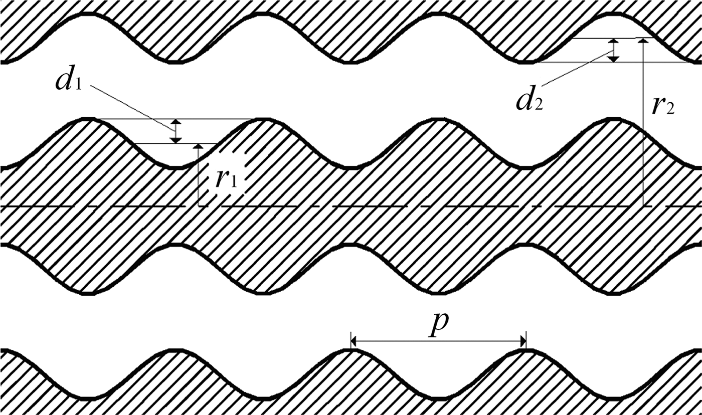
The operation frequency of RBWO can be exactly predicted by analysis of its dispersion relation. The linear dispersion relation of the outer CRBWO with the uniform SWS as shown in Figure 4 can be concluded from the linear analytical method developed by Swegle et al. (Reference Swegle, Poukey and Leifeste1985). The operation point of the outer CRBWO is approximately determined by the intersection between the beam line and its dispersion curve, which is derived by solving the equation
 $$\hbox{det} \left[{\matrix{ {D_a } & {D_b } \cr {D_c } & {D_d } \cr } } \right]=0\comma \;$$
with the infinitesimal electron beam. In Eq. (1), the matrix elements are
$$\eqalign{& D_{a\comma mn}=\left[{{\rm \tau} _n^2+\displaystyle{{2\left({m - n} \right){\rm \pi} } \over p}{\rm \beta} _n } \right]\cr &\quad \vint_{ - \displaystyle{\,p \over 2}}^{+\displaystyle{\,p \over 2}} {I_0 \left[{{\rm \tau} _n \left({r_1 - d_1 \cos \displaystyle{{2{\rm \pi} z} \over p}} \right)} \right]\cos \displaystyle{{2\left({m - n} \right){\rm \pi} z} \over p}dz} \cr & D_{b\comma mn}=\left[{{\rm \tau} _n^2+\displaystyle{{2\left({m - n} \right){\rm \pi} } \over p}{\rm \beta} _n } \right]\cr &\quad \vint_{ - \displaystyle{\,p \over 2}}^{+\displaystyle{\,p \over 2}} {K_0 \left[{{\rm \tau} _n \left({r_1 - d_1 \cos \displaystyle{{2{\rm \pi} z} \over p}} \right)} \right]\cos \displaystyle{{2\left({m - n} \right){\rm \pi} z} \over p}dz} \cr & D_{c\comma mn}=\left[{{\rm \tau} _n^2+\displaystyle{{2\left({m - n} \right){\rm \pi} } \over p}{\rm \beta} _n } \right]\cr &\quad \vint_{ - \displaystyle{\,p \over 2}}^{+\displaystyle{\,p \over 2}} {I_0 \left[{{\rm \tau} _n \left({r_2 - d_2 \cos \displaystyle{{2{\rm \pi} z} \over p}} \right)} \right]} \cos \displaystyle{{2\left({m - n} \right){\rm \pi} z} \over p}dz \cr & D_{d\comma mn}=\left[{{\rm \tau} _n^2+\displaystyle{{2\left({m - n} \right){\rm \pi} } \over p}{\rm \beta} _n } \right]\cr &\quad \vint_{ - \displaystyle{\,p \over 2}}^{+\displaystyle{\,p \over 2}} {K_0 \left[{{\rm \tau} _n \left({r_2 - d_2 \cos \displaystyle{{2{\rm \pi} z} \over p}} \right)} \right]\cos \displaystyle{{2\left({m - n} \right){\rm \pi} z} \over p}dz} }$$where βn = β0 + 2nπ/p is the longitudinal wavenumbers of harmonics, β 0 is the longitudinal wavenumber of the fundamental harmonic, τ n2 = βn2 − ω2μ 0ɛ0, m, and n are harmonics number, μ0 and ɛ0 are the permeability and the permittivity in the vacuum, r 1 and r 2 are inner and outer average radii, d 1 and d 2 are the ripple depth on inner and outer conductors, p is the ripple period, I 0 and K 0 are the modified first-kind and second-kind Bessel function, respectively. However, the linear theory cannot be directly applied to the inner RBWO with the non-uniform SWS. The linear dispersion relation of the inner RBWO can be derived by investigating the transmission between two ports of the non-uniform SWS in the inner RBWO as shown in Figure 5. Calculate the transmission coefficient from Port 1 to Port 2 between the cut-off frequencies of TM01 mode and the higher mode, and the frequencies corresponding to the peak values of the transmission coefficient are just the resonating frequencies on the dispersion curve.
Uniform coaxial SWS in outer CRBWO. Inner and outer average radii are r 1 = 42.0 mm and r 2 = 50.0 mm, respectively. Ripple depth on inner and outer conductors are d 1 = 1.5 mm and d 2 = 2.0 mm. Ripple period p = 14.0 mm.
Nonuniform SWS in inner RBWO. Average radius r 0 = 23.3 mm, average ripple depth d 0 = 1.7 mm, and average ripple period p 0 = 14.0 mm.

The research on the dispersion relation as illustrated in Figure 6 indicates that M-CRBWO generates microwave pulse during the range of 8.9–9.9 GHz driven by the electron beam with 600–700 keV. In Figure 2, the radii of the annular cathodes are r b1 = 20.25 mm, r b2 = 44.75 mm, and r b3 = 47.25 mm from inner to outer, respectively. In the hollow RBWO, the electron beam interacts synchronously with the -1st harmonic and the fundamental harmonic is the fast wave (Swegle et al., Reference Swegle, Poukey and Leifeste1985), while in CRBWO the electron beams interact with both of the -1st and fundamental harmonics which are both slow waves (Liu et al., Reference Liu, Xiao, Chen, Shao, Hu and Wang2008; Teng et al., Reference Teng, Xiao, Liu, Tang, Chen and Shao2010). Thus, the study on the coupling impedance demonstrated in Figure 7 focuses on the -1st harmonic in the inner RBWO and the -1st and fundamental harmonics in the outer CRBWO. It is found that the coupling impedance reaches the maximum value near β0p = π, which implies that operation close to the π point as shown in Figure 6 is beneficial for the enhancement of the conversion efficiency.
(Color online) Dispersion relation of M-CRBWO.
(Color online) Coupling impedance of coaxial annular beams.
Operation of Diode with Coaxial Annular Cathodes
The diode structure with coaxial annular cathodes as shown in the blue pane of Figure 2 plays an important role in the operation of M-CRBWO. When the three coaxial electron beams are emitted synchronously from the coaxial annular cathodes, the space charge effect of the outer annular beams may shield the inner cathode and significantly reduce the electric field on the surface of the inner cathode (Teng et al., Reference Teng, Sun, Chen and Shao2013b). This will terminate the explosive emission of the inner cathode.
However, our theoretical and experimental research on CRBWO has proposed the effective approach to alleviate the shielding effect of the space charge based on the inherent merit of CRBWO. In our structure of CRBWO, the introduction of the inner conductor, which is equi-potentially connected to the outer conductor, can depress the space-charge effect in SWS (Teng et al., Reference Teng, Xiao, Song, Sun, Chen and Shao2011b). This makes it possible that the inner cathode can be prevented from being shielded by the outer annular beams with the help of the equipotential coaxial structure of M-CRBWO. SWSs of M-CRBWO with coaxial annular beams can be qualitatively approximated as the physical model as shown in Figure 8, in which the radius of the cylindrical waveguide is r 1, inner and outer radii of the coaxial waveguide are r 2 and r 3, and the radii of the infinitely thin annular beams from inner to outer are r b1, r b2, and r b3, respectively. The outer conductor is φ(r = r 3) = 0 with respect to the actual experimental situation. Assuming beam currents and the electron velocities of the annular beam are I i and v 0i, i = 1, 2, 3 from inner to outer, the electric potential in different areas can be expressed as
(Color online) Approximate physical model of coaxial waveguide and nested cylindrical waveguide with three coaxial annular beams noted as red solid lines.
$$\left\{\matrix{\matrix{{\rm \phi} \left(r \right) = \displaystyle{{\rm \sigma} r_2 \over {\rm \varepsilon}_0} \ln \displaystyle{r_3 \over r_2} + \displaystyle{I_1 \over 2{\rm \pi} {\rm \varepsilon}_0 v_{01}} \ln \displaystyle{r_{b1} \over r_1} - \displaystyle{I_2 \over 2{\rm \pi} {\rm \varepsilon}_0 v_{02}} \ln \cr \displaystyle{r_3 \over r_{b2}} - \displaystyle{I_3 \over 2{\rm \pi} {\rm \varepsilon}_0 v_{03}} \ln \displaystyle{r_3 \over r_{b3}} &r \lt r_{b1} \hfill \cr \matrix{{\rm \phi} \left(r \right) = \displaystyle{{\rm \sigma} r_2 \over {\rm \varepsilon}_0} \ln \displaystyle{r_3 \over r_2} + \displaystyle{I_1 \over 2{\rm \pi} {\rm \varepsilon}_0 v_{01}} \ln \displaystyle{r \over r_1} \quad \quad \quad \quad \quad \qquad \cr - \displaystyle{I_2 \over 2{\rm \pi} {\rm \varepsilon}_0 v_{02}} \ln \displaystyle{r_3 \over r_{b2}} - \displaystyle{I_3 \over 2{\rm \pi} {\rm \varepsilon}_0 v_{03}} \ln \displaystyle{r_3 \over r_{b3}}} \hfill &r_{b1} \lt r\lt r_1 \hfill \cr {\rm \phi} \left(r \right) = \displaystyle{{\rm \sigma} r_2 \over {\rm \varepsilon}_0} \ln \displaystyle{r_3 \over r} - \displaystyle{I_2 \over 2{\rm \pi} {\rm \varepsilon}_0 v_{02}} \ln \displaystyle{r_3 \over r_{b2}} - \displaystyle{I_3 \over 2{\rm \pi} {\rm \varepsilon} _0 v_{03}} \ln \displaystyle{r_3 \over r_{b3}} \hfill &r_2\lt r\lt r_{b2} \hfill \cr {\rm \phi} \left(r \right) = \displaystyle{{\rm \sigma} r_2 \over {\rm \varepsilon}_0} \ln \displaystyle{r_3 \over r} - \displaystyle{I_2 \over 2{\rm \pi} {\rm \varepsilon}_0 v_{02}} \ln \displaystyle{r_3 \over r} - \displaystyle{I_3 \over 2{\rm \pi} {\rm \varepsilon}_0 v_{03}} \ln \displaystyle{r_3 \over r_{b3}} \hfill &r_{b2}\lt r\lt r_{b3} \hfill \cr {\rm \phi} \left(r \right) = \left(\displaystyle{{\rm \sigma} r_2 \over {\rm \varepsilon}_0} - \displaystyle{I_2 \over 2{\rm \pi} {\rm \varepsilon}_0 v_{02}} - \displaystyle{I_3 \over 2{\rm \pi} {\rm \varepsilon}_0 v_{03}} \right) \ln \displaystyle{r_3 \over r} \hfill &r_{b3}\lt r\lt r_3 \hfill}} \right.$$where σ is the surface charge density on the inner conductor. If in Figure 2 the inner RBWO and the outer CRBWO are not equi-potential, the electric potential of the inner conductor
 $$\eqalign{&{\rm \phi} \left({r=r_1 } \right)={\rm \phi} \left({r=r_2 } \right)=\displaystyle{{{\rm \sigma} r_2 } \over {{\rm \varepsilon} _0 }}\ln \displaystyle{{r_3 } \over {r_2 }} - \displaystyle{{I_2 } \over {2{\rm \pi} {\rm \varepsilon} _0 v_{02} }}\ln \displaystyle{{r_3 } \over {r_{b2} }}\cr &\quad - \displaystyle{{I_3 } \over {2{\rm \pi} {\rm \varepsilon} _0 v_{03} }}\ln \displaystyle{{r_3 } \over {r_{b3} }}\comma \; }$$
is nonzero. There will be more and more negative surface charge density σ accumulated on the inner conductor as both the outer annular beams dump on the inner conductor as shown in Figure 2. So the electric potential of the inner conductor, φ(r = r 1) = φ(r = r 2) < 0, will decrease as illustrated by Eq. (4). As the electric potential of the inner conductor falls, the potential difference between the cathodes and the inner conductor gradually decreases, which exerts severe impact on the explosive emission of the inner cathode. Moreover, accumulation of the negative charge on the inner conductor results in the direct radial electric field between the inner and outer conductors, which will disturb the transmission of the electron beams and degrade their quality. On the contrary, if the inner and outer conductors are equi-potentially connected, the electric potential of the inner conductor φ(r = r 1) = φ(r = r 2) = 0 and the surface charge density on the inner conductor σ = [I 2ln(r 3/r b2)/v 02 + I 3ln(r 3/r b3)/v 03]/2πr 2ln(r 3/r 2) maintains constant. So Eq. (3) can be rewritten as
 $$\matrix{ {\left\{\matrix{{\rm \phi} \left(r \right)=H\ln \displaystyle{{r_{b1} } \over {r_1 }} \hfill &r\lt r_{b1} \hfill \cr {\rm \phi} \left(r \right)=H\ln \displaystyle{r \over {r_1 }} \hfill &r_{b1}\lt r\lt r_1 \hfill \cr {\rm \phi} \left(r \right)=G\left({\displaystyle{{I_2 } \over {v_{02} }}\ln \displaystyle{{r_3 } \over {r_{b2} }}+\displaystyle{{I_3 } \over {v_{03} }}\ln \displaystyle{{r_3 } \over {r_{b3} }}} \right)\ln \displaystyle{{r_2 } \over r} \hfill &r_2\lt r\lt r_{b2} \hfill \cr \matrix{{\rm \phi} \left(r \right)=G\left(\displaystyle{{I_2 } \over {v_{02} }}\ln \displaystyle{{r_2 } \over {r_{b2} }}\ln \displaystyle{{r_3 } \over r}\right. \quad\quad\quad\quad\cr \left.+\displaystyle{{I_3 } \over {v_{03} }}\ln \displaystyle{{r_3 } \over {r_{b3} }}\ln \displaystyle{{r_2 } \over r} \right)} \hfill & r_{b2}\lt r\lt r_{b3} \hfill \cr {\rm \phi} \left(r \right)=G\left({\displaystyle{{I_2 } \over {v_{02} }}\ln \displaystyle{{r_2 } \over {r_{b2} }}+\displaystyle{{I_3 } \over {v_{03} }}\ln \displaystyle{{r_2 } \over {r_{b3} }}} \right)\ln \displaystyle{{r_3 } \over r} \hfill &r_{b3}\lt r\lt r_3 \hfill} \right.} \cr }$$
where H = I 1/2πɛ 0v 01 and G = [2πɛ 0ln(r 3/r 2)]−1. The electric potential of the inner conductor and each beam stay constant during the emission and the transmission of the coaxial, which is beneficial for the stability of the diode performance. And the space charge effect of the outer annular beam becomes weaker due to the equipotential connecting of the inner conductor to the out one (Teng et al., Reference Teng, Xiao, Song, Sun, Chen and Shao2011b).
The distributions of the scalar electric field in the two cases are compared in Figure 9. It is shown in Figure 9a that when the inner and outer conductors are not conductively connected, there is the apparent electric potential difference between the inner and outer conductors as predicted by our previous theoretical research (Liu, Reference Liu2002). Attributed to the shielding of the space charge effect of the outer beams, the electric field on the surface and the tip of the inner cathode is so weak that the explosive emission hardly occurs. On the contrary, when the inner and the outer are connected equi-potentially and serves as the whole equipotential anode, the electric potential difference between the inner and outer conductors disappear while the electric field on the surface and the tip of the inner cathode, up to 700 kV/cm as shown in Figure 9b, is much stronger than that shown in Figure 9a. In fact, in the initial 5–7 ns of the explosive emission, the field distribution in the diode structure with the inner and outer conductors unconnected equi-potentially is similar as that described in Figure 9b. And the two inner cathodes can produce electron beams through explosive emission. But with the increasing of the outer beam current and the accumulation of the negative charge on the inner conductor as predicted by Eq. (4), the field distribution begins to get close to Figure 9a because of the space charge effect, and the currents of the two inner annular beams decreases gradually as demonstrated in Figure 9a. When the performance of the diode with the inner and outer conductors unconnected reaches stability, the first annular beam disappears because of the shielding of the space charge effect, and the current of the second annular beam retains less than 1 kA. On the contrary, all of the coaxial annular cathodes in the diode with the inner and outer conductors connected conductively are able to explosively emit the electron beams due to the alleviation of the space charge effect as shown in Figure 10b.
(Color online) Distribution of scalar electric field in diode structure of M-CRBWO in which inner RBWO and outer CRBWO (a) are not equipotential and (b) are equipotential in steady state.
Variation of beam current produced by coaxial annular cathodes in diodes with inner and outer (a) unconnected equipotentially and (b) connected equi-potentially.

Another method to overcome the shielding of the space charge effect is to make the inner cathode longer than both the outer ones as shown in Figure 2. Both the outer cathodes are of the same length in order to produce two coaxial annular beams with the same kinetic energies (Teng et al., Reference Teng, Sun, Chen and Shao2013b). The relative length, l c as shown in Figure 2, increases monotonically with the inner beam current as shown in Figure 11, which indicates that when l c < 0, i.e., the inner cathode is shorter than both the outer ones, the explosive emission can hardly happen.
(Color online) Variation of inner beam current with relative length l c.
Study on the diode structure of M-CRBWO shows that the electro-dynamic structure of CRBWO is appropriate for the operation of the diode with coaxial annular cathodes. The space charge effect preventing the inner cathodes from explosive emission can be effectively depressed by connecting equi-potentially the inner and outer conductors and by making the inner cathode longer than both the outer ones. However, the space charge effect should not be negligible. Because no matter how much the positive l c is adopted, the inner beam current still fluctuates greatly with time in the first 20 ns and grows slower than two outer ones as shown in Figure 10b. This current fluctuation may delay the startup of the oscillation in the inner RBWO.
Coaxial Transmission Supporter
According to our experience in the physical design and experimental research on CRBWO, the coaxial transmission supporter as shown in Figure 3 developed from the integrative conductive supporter, which is proved to performance efficiently by experiments as described by (Ref. 20), can stably and exactly fix the RBWO into the inner conductor of CRBWO and make the microwave pulse of TEM mode generated from the coaxial SWS transmitted with little reflection. In Figure 3, the TEM mode traveling from Port 2 through the coaxial transmission supporter, is converted into the TM01 mode in the cylindrical waveguide and is incoherently combined with the TM01 mode which is generated by the inner RBWO and travels through the coaxial transmission supporter from Port 1. The combining generation of beating wave is outputted through Port 3.
Research on the coaxial transmission supporter indicates that when TEM mode is inputted from Port 1 and TM01 mode is inputted from Port 2 synchronously, the reflection coefficients of the electric field are less than 0.12 from 8.8 to 10.0 GHz as shown in Figure 12. In other words, the power transmission efficiency is above 98% over the operation frequency range predicted in Figure 6.
(Color online) Reflection coefficients of electric field at (a) Port 1 and (b) Port 2.
NUMERICAL SIMULATION
The 2.5-deminsional PIC simulation code CHIPIC (Zhou et al., Reference Zhou, Liu, Liao and Li2009) is used to investigate and confirm our physical model of M-CRBWO. The three coaxial annular beams, which are explosively emitted from the cathodes synchronously, are transmitted through the reflectors and interact with the structure waves in SWSs. The reflector of the inner RBWO and the coaxial reflector of the outer RBWO cannot only prevent the microwave produced in SWSs from disturbing the operation of the diode, but also pre-modulate the beams to facilitate the wave-beam interaction in SWSs. According to the research shown in Figure 11, the relative length of the inner cathode is l c = 24 mm.
The longitudinal electric fields on the beam transmission lines, which seriously affect the wave-beam interaction, are shown in Figure 13. The longitudinal distance between the two outer cathodes and the anode is longer than that between the inner cathode and the anode. Thus, the accelerating fields on the second and third transmission lines are wider and more uniform than that on the first one. The electric field on the tip of the inner cathode is strong enough to induce the explosive emission, which confirms that space charge effect of the outer beams is depressed effectively. It is found in Figure 13 that the intense standing field is excited in the reflector of the inner RBWO to pre-modulate the electron beams. Likewise, the strong standing fields on the second and third lines, which are produced by two cavities on the inner and outer conductors of the coaxial reflectors, can pre-modulate the two electron beams injected into the outer CRBWO, respectively. The intense longitudinal field on the first transmission line rises from the abstracting cavity of the inner RBWO in order to further extract the power from the inner electron beams. And in the outer CRBWO the strong longitudinal fields on the points where the two outer beams dump is also beneficial for the wave-beam interaction. Besides, it is concluded from Figure 13 that the field on the third transmission line is stronger than that on the second transmission line, which corresponds to that fact shown in Figure 7 that the coupling impedance at r = 47.25 mm is larger than that at r = 44.75 mm.
(Color online) Longitudinal electric field on first, second and third transmission line from inner to outer.
The phase space as shown in Figure 14 illustrated that all three coaxial annular beams are formed in bunches with the better quality in the inner RBWO and the outer RBWO. Bunches of both the outer beams are well synchronous with each other for they interact with the electromagnetic field at the same frequency. The initial bunch of the inner electron beam starts up in the inner reflector while that of the two outer beams starts up in the coaxial reflector. The bunch of the inner beam at the end of the inner RBWO is still uniform due to the abstracting cavity, which is in favor of the enhancement of the conversion efficiency. It is demonstrated in Figure 14 that many electrons of both the outer beams are decelerated seriously to zero-velocity and even are forced to move in the opposite direction, which shows that the outer CRBWO works in the over bunched state (Levush, Reference Levush, Antonsen, Bromborsky, Lou and Carmel1992).
(Color online) Phase space of three coaxial annular beams.
The beating wave of HPM pulse at the frequencies of 9.0 and 9.7 GHz, which corresponds to the operation range of the coaxial transmission supporter as shown in Figure 14, is generated when the diode voltage and current are 724 and 19.57 kA as demonstrated in Figure 15. The beam currents are 6.88, 3.46, and 9.23 kA from inner to outer. In Figure 15a, the violent modulation of the waveform implies that the electric field includes of more than one frequency component as illustrated in Figure 15b, in which the spectrum of the beating generation are pure and stable. The average power of the beating wave as shown in Figure 16a is 5.88 GW, and the conversion efficiency is 41.5%, in which the generation powers of the inner RBWO and the outer CRBWO are 2.23 GW at 9.7 GHz and 3.65 GW at 9.0 GHz, respectively. In Figure 16a, the modulation frequency of the waveform envelop described by the blue line corresponds to the beating frequency of 700 MHz.
(Color online) Beating wave of HPM pulse generated by M-CRBWO. (a) Instantaneous waveform of electric field; (b) Spectrum of electric field.
(Color online) (a) Instantaneous power waveform of beating wave. Blue line describes power envelop; (b) Spectrum of power waveform.
The microwave generation of TEM mode from the outer CRBWO is converted into TM01 mode and is incoherently combined in the cylindrical waveguide with the microwave of TM01 mode generated from the inner RBWO. Assuming the frequencies of the generations from the inner RBWO and outer CRBWO are f 1 = ω1/2π = 9.7 GHz and f 2 = ω2/2π = 9.0 GHz. And the transverse electromagnetic filed at ω 1 and ω 2 can be expressed as E T1cos(ω1t − β1z)îr, E T1cos(ω1t − β1z)îθ/η 1 and E T2cos(ω2t − β2z + φ)îr, E T2cos(ω2t − β2z + φ)îθ/η 2, where η1 = β 1/ω 1ε 0 and η 2 = β 2/ω2ɛ 0 are the wave impedances, β 1 and β 2 are the longitudinal wavenumbers at ω1 and ω2, φ is the phase shift, îr, îθ and îz are the unit vectors in the radial, azimuthal and axial direction, respectively. Therefore, the Poynting vector in the cylindrical waveguide is
 $$\eqalignno{\vec S &=\left[{E_{{\rm T}1} \cos \left({{\rm \omega} _1 t - {\rm \beta} _1 z} \right)+E_{{\rm T2}} \cos \left({{\rm \omega} _2 t - {\rm \beta} _2 z+{\rm \varphi} } \right)} \right]\hat i_r \cr &\quad \times \left[{\displaystyle{{E_{{\rm T}1} } \over {{\rm \eta} _1 }}\cos \left({{\rm \omega} _1 t - {\rm \beta} _1 z} \right)+\displaystyle{{E_{{\rm T2}} } \over {{\rm \eta} _2 }}\cos \left({{\rm \omega} _2 t - {\rm \beta} _2 z+{\rm \varphi} } \right)} \right]\hat i_{\rm \theta} \cr &=\displaystyle{{E_{{\rm T}1}^2 } \over {{\rm \eta} _1 }}\cos ^2 \left({{\rm \omega} _1 t - {\rm \beta} _1 z} \right)\hat i_z+\displaystyle{{E_{{\rm T}2}^2 } \over {{\rm \eta} _2 }}\cos ^2 \left({{\rm \omega} _2 t - {\rm \beta} _2 z+{\rm \varphi} } \right)\hat i_z \cr &\quad +\left({\displaystyle{{E_{{\rm T}1} E_{{\rm T2}} } \over {{\rm \eta} _1 }}+\displaystyle{{E_{{\rm T}1} E_{{\rm T2}} } \over {{\rm \eta} _2 }}} \right)\cos \left({{\rm \omega} _1 t - {\rm \beta} _1 z} \right) \cos \left({{\rm \omega} _2 t - {\rm \beta} _2 z+{\rm \varphi} } \right)\hat i_z \cr &=\displaystyle{{E_{{\rm T}1}^2 } \over {2{\rm \eta} _1 }}\left[{1+\cos 2\left({{\rm \omega} _1 t - {\rm \beta} _1 z} \right)} \right]\hat i_z \cr &\quad +\displaystyle{{E_{{\rm T}2}^2 } \over {2{\rm \eta} _2 }}\left[{1+\cos 2\left({{\rm \omega} _2 t - {\rm \beta} _2 z+{\rm \varphi} } \right)} \right]\hat i_z \cr &\quad +\displaystyle{{E_{{\rm T}1} E_{{\rm T2}} } \over 2}\left({\displaystyle{1 \over {{\rm \eta} _1 }}+\displaystyle{1 \over {{\rm \eta} _2 }}} \right)\lcub \cos \lsqb \left({{\rm \omega} _1+{\rm \omega} _2 } \right)t - \left({{\rm \beta} _1+{\rm \beta} _2 } \right)\cr &\quad z+{\rm \varphi} \rsqb +\cos \lsqb \left({{\rm \omega} _1 - {\rm \omega} _2 } \right)t - \left({{\rm \beta} _1 - {\rm \beta} _2 } \right)z - {\rm \varphi} \rsqb \rcub \hat i_z &}$$
From Eq. (6) it can be concluded that besides the direct component the power spectrum of the beating wave has other four components, i.e., 2f 1 = 19.4 GHz, 2f 2 = 18.0 GHz, f 1 + f 2 = 18.7 GHz, and |f 1 − f 2| = 700 MHz as described in Figure 16b.
When fed with the coaxial annular cathodes synchronously, the generations of the inner RBWO and the outer CRBWO are demonstrated in Figures 17 and 18. Through comparing the instantaneous waveforms of electric field produced by the inner RBWO and outer CRBWO as shown in Figures 17a and 18a, it is found that the oscillation in the inner RBWO, which reaches the saturation at about 20 ns, starts up later than that in the outer CRBWO. This delay is caused by the fluctuation of the inner beam current in the initial stage due to the space charge effect of the two outer electron beams as shown in Figure 10b. The generation spectrums of the inner RBWO and the outer CRBWO are optimized to be clear and pure as shown in Figures 17b and 18b. This is beneficial for the incoherent combination of the generations. The generations as shown in Figures 17 and 18, which are obtained when the inner RBWO and the outer CRBWO of M-CRBWO are driven synchronously by the coaxial annular cathodes at on shot, are very similar to those when they are running separately driven by two different accelerators. This is because in M-CRBWO the inner RBWO and the outer CRBWO operate independently from each other.
(Color online) Generation of inner RBWO. (a) Instantaneous waveform of electric field; (b) Spectrum of electric field.
(Color online) Generation of outer CRBWO. (a) Instantaneous waveform of electric field; (b) Spectrum of electric field.
Because the inner RBWO and the outer CRBWO are optimized numerically and theoretically before they are assembled together into M-CRBWO, the average total power exceeds 4 GW and the conversion efficiency is higher than 35% from 630 kV to 780 kV as shown in Figure 19a. Compared to the researches on the beating-wave generator reported previously (Wang et al., Reference Wang, Qin, Chen, Wen and Jin2011; Tang et al., Reference Tang, Meng, Li, Zheng, Wang and Zhang2013), M-RBWO is expected to promote the generation of the HPM beating wave up to the present level of RBWO with output power 3 GW–5 GW and conversion efficiency 30–40% (Polevin et al., Reference Polevin, Korovin, Kovalchuk, Karlik, Kurkan, Ozur, Pegel, Proskurovsky, Sukhov and Volkov2004). The output powers of the inner RBWO and the outer CRBWO keep increasing monotonically as the diode voltage until 760 kV. The conversion efficiency is not very sensitive to the diode voltage, which is convenient for the experimental research as our next step. Besides, it is shown in Figure 19b that the two frequencies generated by M-CRBWO vary a little with the diode voltage over that range from 630 kV to 780 kV.
(Color online) Variation of (a) output power and conversion efficiency, and (b) frequency with diode voltage.
The diode currents increase with the diode voltage as shown in Figure 20. The second beam current, the smallest one among the three beam currents, increases less than 900 A from 630 to 780 kV. The diode impedance, which keeps staying at about 36–38 Ω over the voltage range of 150 kV, matches with that of the transmission line of our accelerators such as SINUS 881 (Teng et al., Reference Teng, Xiao, Song, Jun, Chen and Shao2011a; Reference Teng, Chen, Shao, Sun, Song, Xiao and Du2013a) or TPG-series repetitive pulsed accelerator (Peng et al., Reference Peng, Su, Song, Wang, Pan, Zhang, Guo, Huang, Fang, Li, Sun, Zhao, Wang and Liu2010).
(Color online) Variation of diode currents and impedance with diode voltage.
CONCLUSION
This paper presents M-CRBWO that can generate beating wave of HPM pulse with high output power and conversion efficiency driven by a single accelerator at one shot. M-CRBWO makes full use of the structure of CRBWO and employs the coaxial annular cathodes which need merely a single guiding magnet system. The average power of 5.88 GW consisting of two frequency components 9.0 and 9.7 GHz, which corresponds to the microwave power of 2.23 and 3.65 GW, has been obtained in the case of the diode voltage and current 724 and 19.57 kA. The conversion efficiency is up to 41.5%. The equi-potential connecting between the inner and outer conductors can depress the space charge effect in the diode structure and ensure the explosive emission of the coaxial annular cathodes. Our research on M-CRBWO not only increases the power conversion efficiency up, but also makes it a matched load for our accelerator in order to eliminate the power reflection at the diode and to increase the energy efficiency of the total system (Li et al., Reference Li, Shu, Zhang, Yang and Yuan2010; El'chaninov et al., Reference El'chaninov, Klimova, Koval'chuk, Mesyats, Pegel, Romanchenko, Rostova, Sharypov and Yalandin2011).
Although the notably high output power and conversion efficiency are obtained in the numerical simulation, some important problems should be considered carefully in the experimental research as the next step. In experiment, the operation of M-CRBWO is significantly affected by the production and the transmission of the three coaxial annular beams. Our experimental research has indicates that the micro defects on the cathodes are likely to destroy the uniformity of the explosive emission (Sun et al., Reference Sun, Liu, Lin and Xiao2005). And if the plasmas produced by the two outer annular cathodes expand radially and are combined with each other, the two outer annular beams may merge into one thick annular beam. Moreover, the transmission of the two outer annular beams can be disturbed by the repulsion force between them, which will deteriorate the beam quality by increasing their transverse movement. Besides, poor co-axiality of the structure, which makes the transmission of the annular beams chaotically, is proved to result in the reduction of the output power and efficiency (Liu et al., Reference Liu, Xiao, Chen, Shao, Hu and Wang2008). For these problems, we are able to develop some effective methods according to the previous theoretical and experimental researches in order to improve the production and the transmission of the three coaxial annular beams. In our lab the advanced precision machining technology and the post-processing has been adopted to manufacture the explosive-emission cathodes and to eliminate their micro defects. Before the experiment the microscope is used to check the micro surface of the cathodes to ensure the uniformity of the explosive emission (Liu et al., Reference Liu, Sun, Shao, Chen and Zhang2009). In experiment, the radial expansion speed of the cathode plasma can be limited no more than 1 cm/μs with the guide magnetic field higher than 1 T (Kovalev et al., Reference Kovalev, Nechaev, Petelin and Zaitsev1998). So the radial expansion of the cathode plasma can be confined in 1 mm during the pulse width of 100 ns. This makes the diode with coaxial annular cathodes performs stably. In the numerical simulation and experiments, the repulsion force between the two outer annular beams are reduced by making the two beams travel at the radial positions between which the difference of the electric potentials is very small and the repulsion force can be neglected (Teng et al., Reference Teng, Sun, Chen and Shao2013b). Moreover, the co-axiality between the inner and outer conductors can be ensured by our improved structure with the integrative conductive supporter, which is similar as the coaxial transmission supporter as shown in Figure 3 (Teng et al., Reference Teng, Xiao, Song, Jun, Chen and Shao2011a). As a result, in experimental research of M-CRBWO, the conversion efficiency higher than 35% can be expected.
The proposal of M-CRBWO not only puts up a compact generator as shown in Figure 2 to produce the beating wave of HPM pulse, but also provides a practical method and platform of organizing multiple source devices to realize the synchronous composite HPM output of several narrow-band pulses at one shot. The generation of HPM pulses at single frequency can hardly satisfy the actual application, especially the military application for the various targets in the complicated situation. Therefore, M-CRBWO can be expanded into the configuration as shown in Figure 21. As a result, HPM generation combining different frequency components, or different output powers, or different pulse widths, will be obtained. Our research will concentrate on this scalable HPM generating platform as the next step.
(Color online) Expanded M-CRBWO. (1) guide magnet solenoid; (2) coaxial annular cathodes; (3) inner RBWO; (4) middle CRBWO; (5) outer CRBWO.