I. INTRODUCTION
Recent technological advances and trends in consumer electronics have led to a significant increase in the complexity of wireless communication circuits. At the same time, the commoditization of wireless components has considerably increased competition and made reducing the design cycle, and thus the time-to-market, an important competitive advantage for the industry. Microwave microelectromechanical systems (MEMS) have become important components in many modern radio frequency (RF) circuits as they provide significant added value in terms of cost, size, and weight reduction to circuits, such as matching networks, phase shifters, voltage-controlled oscillators, filters, antennas, and impedance tuners [Reference Girbau, Otegi, Pradell and Lazaro1–Reference Rebeiz3]. The increased popularity of RF MEMS devices and technologies has resulted in novel integrated circuits and systems that incorporate them. Consequently, the development of new state-of-the-art computer-aided design (CAD) tools for accurate modeling and efficient simulation of such systems is now required. These new CAD tools must be capable of capturing both the electrical characteristics of the circuit and the dynamic mechanical behavior of the MEMS devices [Reference Dussopt and Rebeiz4–Reference Gaddi, Iannacci and Gnudi6].
From the perspective of the RF circuit designer, one of the most important performance characteristics that must be accounted for is the nonlinear intermodulation distortion, which can significantly affect circuit performance and output RF power levels. Until recently, RF MEMS devices were assumed to be intermodulation-free devices, since they do not contain a semiconductor junction and therefore do not have an exponential current–voltage relationship. However, it has since been proven that with MEMS variable capacitors, significant third and higher order intermodulation products are generated by the nonlinear dependence of the membrane displacement on the applied voltage [Reference Girbau, Otegi, Pradell and Lazaro1, Reference Girbau, Otegi, Pradell and Lazaro7, Reference Innocent, Wambacq, Donnay, Tilmans, Sansen and Man8]. The simulation of nonlinear distortion is one of the most important bottlenecks in the design automation of RF circuits. This distortion is due to the inherent nonlinearity of circuit components and results in the harmonics of input tones, as well as the intermodulation products, being present at the output. Of particular interest are the odd-order intermodulation products, such as the third and fifth order intermodulation tones, because they mix back into the frequency band of operation and result in many undesirable effects, such as gain compression [Reference Wambacq and Sansen9]. The most common metric for characterizing and quantifying the in-band distortion caused by the third-order nonlinearity is the third-order intercept point (IP 3) [Reference Rogers and Plett10].
In a simulation environment, the most common approach for determining intercept points is to mimic laboratory measurements by applying a two-tone test input and performing a steady-state analysis using techniques, such as the harmonic balance method [Reference Kundert, White and Sangiovanni-Vincentelli11, Reference Nakhla and Vlach12]. This approach is general and gives very accurate results. However, the harmonic balance simulation requires a large computational cost because of the large number of variables present due to the multi-tone inputs. In the presence of MEMS variable capacitors, there is the added challenge of having to solve the ordinary electric circuit equations simultaneously with the nonlinear electromechanical equations that describe the dynamics of motion in the device, which could exhibit singularities in some regions of the state variable space [Reference Rizzoli, Gaddi, Iannacci, Masotti and Mastri13, Reference Rizzoli, Masotti, Mastri and Costanzo14]. This typically leads to numerical ill-conditioning and poor convergence of the solution. Alternatively, Volterra series analytical techniques can be employed to measure the distortion in circuits that contain MEMS devices. In [Reference Innocent, Wambacq, Donnay, Tilmans, Sansen and Man8], analytic Volterra series-based models were developed for MEMS variable capacitors. However, the same challenges associated with traditional circuits remain, that is, the complexity of deriving the higher order kernels necessary for determining the intercept points.
In [Reference Rizzoli, Gaddi, Iannacci, Masotti and Mastri13, Reference Veijola15], the harmonic balance method was extended to cover the simulation of nonlinear circuits containing MEMS variable capacitors. This was accomplished by including the membrane displacement as an additional variable in the harmonic balance formulation. In [Reference Rizzoli, Gaddi, Iannacci, Masotti and Mastri13], additional state variables were incorporated to remove the MEMS equation singularities along with numerical techniques that improve conversion. However, the main computational bottlenecks in the classical harmonic balance algorithm remain. In [Reference Tannir and Khazaka16–Reference Tannir and Khazaka18], a method for computing IP 3 using moments analysis was presented. This method links the value of IP 3 to the moments of the two-tone harmonic balance equations using closed form expressions. The computation of IP 3 was thus reduced to finding the moments of the harmonic balance equations, without the need for a harmonic balance simulation, thus resulting in a considerable computation speed-up. However, this approach was limited to traditional semiconductor-based RF circuits.
In this paper, we show, for the first time, how the moments approach that was first presented in [Reference Tannir and Khazaka16–Reference Tannir and Khazaka18], can be developed to cover a new class of circuits which contain MEMS variable capacitors. To that end, the modified moments computation algorithm, which includes the mechanical membrane displacement as a variable, is presented. In addition, the derivation of the expansion of the derivatives for the MEMS device nonlinearities, which are required for the moments computation algorithm, are also presented. For this modified moments algorithm, we will show that the considerable computation cost advantage that moments analysis has over performing a full harmonic balance simulation is preserved. Finally, it is important to emphasize that the moments approach does not require iterative solutions, and therefore avoids some of the convergence problems associated with solving the harmonic balance equations for RF MEMS circuits.
This paper is organized into six sections. Following the introduction, Section II provides an overview on the modeling of MEMS nonlinearities while Section III provides an overview of the moments based method for IP 3 computation in semiconductor RF circuits. The proposed algorithm is presented in Section IV including the extended formulation of the system equations and the derivation of all the numerical terms required for determining the value of IP 3 of circuits that contain MEMS nonlinearities. Finally a numerical example is described in Section V in order to illustrate the speedup and accuracy of the new method, followed by conclusions in Section VI.
II. OVERVIEW OF MEMS CAPACITOR MODELING
The dynamics of motion for a two-parallel plate topology electrostatic actuation can be expressed using a second-order nonlinear differential equation of a mass-spring-damper system as [Reference Girbau, Otegi, Pradell and Lazaro1, Reference Rizzoli, Gaddi, Iannacci, Masotti and Mastri13]
 $$m\displaystyle{{{d^2}z} \over {d{t^2}}}+b\displaystyle{{dz} \over {dt}}+kz=\displaystyle{1 \over 2}\displaystyle{{{{\rm \epsilon }_0}A{V^2}} \over {{{\lpar d - z\rpar }^2}}}\comma \;$$
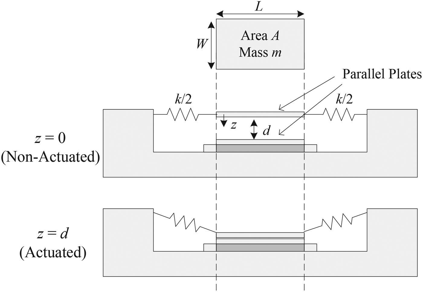
where z is the membrane displacement, m is the mass, b is the damping coefficient, k is the suspension stiffness, d is the initial gap, A is the area of the electrode,  ${{\rm \epsilon }_0}$ is the permittivity of free space, and V is the applied voltage. These parameters are illustrated in Fig. 1.
Cross-section of an RF MEMs capacitor in the (a) unactuated and (b) actuated positions.

The main parameters of interest when using a MEMS variable capacitor in an electric circuit are the charge Q on the plates, and the voltage V across them [Reference Innocent, Wambacq, Donnay, Tilmans, Sansen and Man8]. The charge Q is a function of the voltage V in addition to the membrane displacement z as follows
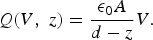 $$Q\lpar V\comma \; z\rpar =\displaystyle{{{{\rm \epsilon }_0}A} \over {d - z}}V.$$
Combining the relation in (2) with the MEMS equation in (1) allows us to express the equation of motion as a nonlinear function of charge as follows:
 $$m\displaystyle{{{d^2}z} \over {d{t^2}}}+b\displaystyle{{dz} \over {dt}}+kz=F\lpar Q\rpar =\displaystyle{{{Q^2}} \over {2{{\rm \epsilon }_0}A}}.$$
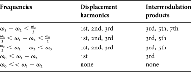
The mechanical resonance frequency of the MEMS device is defined as  ${\omega _0}=\sqrt {k/m} $ [Reference Rebeiz and Muldavin2]. For an accurate multi-domain simulation that captures both the electrical and mechanical properties of the system, the simulator must solve for the displacement variable z in addition to the capacitor charge Q and the voltage V. A summary of the distortion components due to the membrane displacement harmonics as well as the intermodulation products for a circuit containing a MEMS variable capacitor that is subjected to a two-tone test (at frequencies ω 1 and ω 2) is provided in Table 1 [Reference Girbau, Otegi, Pradell and Lazaro1].
Frequency components present in displacement and intermodulation products [Reference Girbau, Otegi, Pradell and Lazaro1].
In this paper, we show how the relations in (2) and (3) can be incorporated in the moments algorithm for distortion analysis. Note that the nonlinear electromechanical equations of the MEMS motion given by (1–3) are based on the simplified 1-D model described in the literature [Reference Girbau, Otegi, Pradell and Lazaro1, Reference Rebeiz3, Reference Rizzoli, Gaddi, Iannacci, Masotti and Mastri13, Reference Veijola15]. However, it is important to emphasize that more detailed expressions can be added to better describe the nonlinear behavior of the MEMS model. In this paper, for simplicity of presentation, we will restrict the analysis to the model described by (1–3), with a brief discussion on how more refined models can be incorporated and what their effects will be on the computation cost of the proposed method provided in Section IV.D.
III. OVERVIEW OF MOMENTS BASED IP3 COMPUTATION
In [Reference Tannir and Khazaka17], an efficient method for computing IP 3 of semiconductor-based RF amplifier and mixer circuits based on moments analysis was presented. The RF circuit was modeled using the general harmonic balance formulation for nonlinear systems. The formulation of the system was followed by the computation of the moments of the output vector, rather than the computation of the steady-state response, as is the case with a regular harmonic balance simulation. The moment vectors, once determined, were shown to contain the numerical values of the Volterra kernels that are required to determine the value of IP 3 according to the Volterra series formulation. The Volterra series approach, which is an extension of Taylor series to nonlinear systems with memory, works well for circuits that are mildly nonlinear [Reference Wambacq and Sansen9]. This is therefore also the case when performing distortion analysis using the moments method. An overview of the formulation, computation of the moments, and the closed form relation between IP 3 and the moments are presented in this section. For the complete details of the method and numerical examples, the reader is encouraged to refer to the literature [Reference Tannir and Khazaka16–Reference Tannir and Khazaka18].
A) Moments of the harmonic balance equations
The moments computation algorithm is applied to a general nonlinear system described by its harmonic balance equations [Reference Gad, Khazaka, Nakhla and Griffith19]. The harmonic balance formulation is derived from the modified nodal analysis (MNA) formulation for a nonlinear system in the time domain which is of the form [Reference Ho, Ruehli and Brennan20]
 $${\bi Gx}\lpar t\rpar +{\bi Cx}\lpar t\rpar +{\bi f}\lpar {\bi x}\lpar t\rpar \rpar ={\bi b}\lpar t\rpar \comma \;$$
where  $x\lpar t\rpar \in {\rm {\opf R}}^n$ is a vector of n unknown variables consisting of node voltages and branch currents.
 ${\bi G} \in {{{\rm \opf R}}^{n \times n}}$ and
 ${\bi C} \in {{\rm \opf R}^{n \times n}}$ are matrices representing the contributions of the linear memory less and memory elements, respectively.
 ${\bi f}\lpar x\rpar \in {{\rm \opf R}^n}$ and
 ${\bi b}\lpar t\rpar \in {{\rm \opf R}^n}$ are the vectors of nonlinear equations and the independent sources, respectively.
The harmonic balance equations can be obtained from the formulation in (4) by expressing the vector of variables x(t) as a Fourier Series of H harmonics given by:
 $$x\lpar t\rpar ={{\bi A}_0}+\sum\limits_{k=1}^H \, \left({{{\bi A}_k}{\rm cos}\lpar {\omega _k}t\rpar +{{\bi B}_k}{\rm sin}\lpar {\omega _k}t\rpar } \right).$$
In this case, the number of variables in the formulation increases to N h and the harmonic balance equations can be expressed as:
 $$\bar{\bi GX}+\bar{\bi CX}+{\bi F}\lpar {\bi X}\rpar ={{\bi B}_{DC}}+\alpha {{\bi B}_{RF}}.$$
In this formulation,  ${\bi X} \in {{\rm \opf R}^{{N_h}}}$ is a vector of unknown cosine and sine coefficients for each of the variables in x(t). The vectors
 ${{\bi B}_{DC}} \in {{\rm \opf R}^{{N_h}}}$ and
 ${{\bi B}_{RF}} \in {{\rm \opf R}^{{N_h}}}$ contain the contributions of the dc and the RF signal sources, respectively. In this paper, α refers to the amplitude of the input RF voltage signal.
 $\bar{\bi G} \in {{\rm \opf R}^{{N_h} \times {N_h}}}$ and
 $\bar{\bi C} \in {{\rm \opf R}^{{N_h} \times {N_h}}}$ are block matrices representing the contributions of the linear memoryless and memory elements, respectively, and
 ${\bi F}\lpar {\bi X}\rpar \in {{\rm \opf R}^{{N_h}}}$ is the vector of nonlinear equations which also includes the nonlinear charge expressions.
The moments of the system are defined as the coefficients of the Taylor series expansion of the output solution vector X with respect to the input RF amplitude α. This can be expressed as
 $${\bi X}={{\bi M}_0}+{{\bi M}_1}\alpha+{{\bi M}_2}{\alpha ^2}+{{\bi M}_3}{\alpha ^3}+\ldots=\sum\limits_{k=0}^\infty \, {{\bi M}_k}{\alpha ^k}\comma \;$$
where Mk is the kth moment vector and can also be expressed as [Reference Gad, Khazaka, Nakhla and Griffith19]:
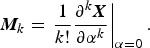 $${{\bi M}_k}=\mathop {\left. {\displaystyle{1 \over {k!}}\displaystyle{{{\partial ^k}{\bi X}} \over {\partial {\alpha ^k}}}} \right\vert }\nolimits_{\alpha=0} .$$
It is important to note that the Jacobian matrix of the harmonic balance equations given in (6) is typically large and block dense, therefore making the harmonic balance solution computationally expensive. Alternatively, the moments method does not require performing a harmonic balance simulation, but rather computes the moments defined in (7) using a sparse moments matrix, thereby presenting significant computation cost reduction.
B) Moments computation algorithm
The moments computation algorithm has been presented several times in the literature [Reference Achar and Nakhla21–Reference Chiprout and Nakhla23] and has many useful applications in electronic circuit simulation, such as in model order reduction based simulation methods. In this section, an overview of the moments computation algorithm is presented, with an explanation of what makes the algorithm very computationally attractive for distortion analysis applications. For the full details of the algorithm, the reader is invited to refer to the literature [Reference Tannir and Khazaka17, Reference Achar and Nakhla21–Reference Chiprout and Nakhla23].
The moments computation algorithm is about determining the unknown moment vectors, Mk, when the vector of unknown variables X is expressed using (7). Just as is the case with Taylor series, the moments expansion has a finite radius of convergence, thereby limiting their application to circuits that are mildly nonlinear in the signal path. The moments expansion for general mildly nonlinear amplifier circuits is therefore carried out at the DC operating point, which must be computed first as the ‘zero’ moment vector, as will be shown next. To account for stronger nonlinearities that occur outside the RF signal path, such as when simulating mixer circuits with a high power local oscillator, the moments expansion must be carried out at the local oscillator operating point, as shown in [Reference Tannir and Khazaka17].
The main steps of the moments computation algorithm for amplifier circuits are as follows:
− The zero moment vector, M0, is obtained by finding the solution of the system described by (6) with the RF amplitude (α) set to zero. This is equivalent to obtaining the dc solution of the system.
− The first moment vector, M1, is obtained by using one LU decomposition to solve the relation given by
(9)where the matrix Φ is the sparse moment computation matrix which has the same structure as a harmonic balance Jacobian, but contains only dc spectral components. It is defined as $${\bf \Phi }{{\bi M}_1}={{\bi B}_{RF}}\comma \;$$(10)Note that the matrices$${\bf \Phi }=\mathop {\left. {\bar{\bi G}+\bar{\bi C}+\displaystyle{{\partial {\bi F}\lpar {\bi X}\rpar } \over {\partial {\bi X}}}} \right\vert }\nolimits_{\alpha=0} .$$$\bar{\bi G}$ and $\bar{\bi C}$ are very sparse, while the Jacobian of the nonlinear vector F(X) is given by
(11)$$\displaystyle{{\partial {\bi F}\lpar {\bi X}\rpar } \over {\partial {\bi X}}}=\left[{\matrix{ {\displaystyle{{\partial {F_1}} \over {\partial X1}}} & \cdots & {\displaystyle{{\partial {F_1}} \over {\partial Xn}}} \cr \vdots & \ddots & \vdots \cr {\displaystyle{{\partial {F_n}} \over {\partial X1}}} & \cdots & {\displaystyle{{\partial {F_n}} \over {\partial Xn}}} \cr } } \right].$$
In a standard harmonic balance Jacobian, each
$\displaystyle{{\partial {F_j}} \over {\partial Xi}}$ term is, when present, a full block matrix which is not the case with the moments matrix since it is evaluated with the RF amplitude set to zero [Reference Gad, Khazaka, Nakhla and Griffith19].− The remaining moment vectors, Mn, are found by solving the following recursive relation
(12)$${\bf \Phi }{{\bi M}_n}=- n\sum\limits_{j=1}^{n - 1} \, \lpar n - j\rpar {{\bi T}_j}{{\bi M}_{n - j}}.$$− In this relation, Tj is a matrix that contains the jth moment of the derivatives of the nonlinear equations.

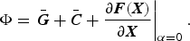


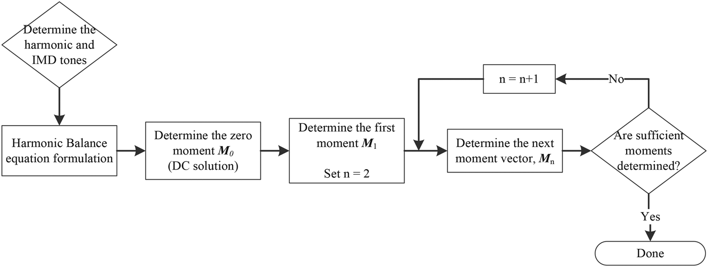
As can be seen from (9) to (12), the computation of the moment vectors is a solution of a set of linear algebraic equations where the left-hand-side matrix (Φ) is the same throughout. A summary of the moments computation algorithm is given in the flowchart of Fig. 2.
Moments computation algorithm flowchart.
C) Link between the moment vectors and IP 3
The input–output relation of a nonlinear circuit can be expressed using a Volterra series as [Reference Maas24]
 $$x\lpar t\rpar ={{\bi H}_0}+{{\bi H}_1}\lsqb {v_{in}}\lpar t\rpar \rsqb +{{\bi H}_2}\lsqb {v_{in}}\lpar t\rpar \rsqb +{{\bi H}_3}\lsqb {v_{in}}\lpar t\rpar \rsqb +\ldots\comma \;$$
where Hn is the nth Volterra operator. When the values of the Volterra kernels ( ${{\bi H}_n}\lpar j{\omega _1}\comma \; \ldots\comma \; j{\omega _n}\rpar $) can be analytically obtained at specific frequency values, we can say that the IP 3 of amplifier circuits can be determined using
 $$I{P_3}=\sqrt {\displaystyle{4 \over 3}\displaystyle{{\vert {{\bi H}_1}\lpar j{\omega _1}\rpar \vert } \over {\vert {{\bi H}_3}\lpar j{\omega _1}\comma \; j{\omega _1}\comma \; - j{\omega _2}\rpar \vert }}} .$$
In [Reference Tannir and Khazaka16–Reference Tannir and Khazaka18], it was shown that the kernels required to determine IP 3 according to (14) were obtained numerically from the first and third moment vectors. This allowed us to express the relation for computing IP 3 as
 $$I{P_3}=\sqrt {\displaystyle{{\vert {{\bi M}_1}\lsqb {\omega _1}\rsqb \vert } \over {\vert {{\bi M}_3}\lsqb 2{\omega _1} - {\omega _2}\rsqb \vert }}}\comma \;$$
where M1[ω 1] is the numerical entry in the first moment vector at the fundamental frequency, and M3[2ω 1 − ω 2] is the numerical entry in the third moment vector at the third-order intermodulation frequency.
IV. MOMENTS METHOD FOR RF MEMS VARIABLE CAPACITORS CIRCUITS
In [Reference Rizzoli, Gaddi, Iannacci, Masotti and Mastri13, Reference Veijola15], it was shown that the harmonic balance method can be extended to include equations that describe the nonlinear behavior of MEMS switches. In [Reference Innocent, Wambacq, Donnay, Tilmans, Sansen and Man8], it was shown that the expression for determining IP 3 given in (14) can also be applied to MEMS variable capacitor circuits. In this paper, we expand the moments method to allow for the numerical evaluation of the expressions needed for computing IP 3 in circuits containing MEMS variable capacitor devices using the relation given in (14), without the need to perform a full harmonic balance simulation. The new extended moments method is general for arbitrary circuit configurations, and is not restricted in frequency. As a result, the method presents a true general purpose approach for the analysis of nonlinear RF circuits that contain MEMS devices and therefore has the potential to solve new classes of nonlinear circuits in an efficient manner.
The new moments computation algorithm is based on the extended formulation defined in [Reference Rizzoli, Gaddi, Iannacci, Masotti and Mastri13] whereby the MEMS switch is described as a nonlinear charge-controlled capacitor whose relations depend on two variables, namely the RF voltage and the displacement. We will begin with the formulation of the extended system equations in a way that facilitates the computation of the new moments. This will then be followed by a description of the new moments computation algorithm and the derivations of the partial derivatives of the MEMS equation nonlinearities.
A) Extended formulation of system equations
Consider a nonlinear circuit excited by one or more input tones and containing a MEMS variable capacitor. The electrical steady-state solution can be obtained using the harmonic balance approach by expressing the periodic solution as a truncated series of sine and cosine functions at the harmonics of the inputs as well as at the intermodulation products. This results in a set of nonlinear algebraic equations in the form given by (6). In order to account for the mechanical characteristics of the MEMS device, this formulation has to be expanded to include the MEMS mechanical dynamic model nonlinearities. Therefore, additional variables for the charge of the nonlinear capacitor (q(t)) and the displacement of the membrane (z(t)) must be accounted for alongside the regular unknown node voltages and currents of the MNA formulation [Reference Ho, Ruehli and Brennan20]. For a general system containing a MEMS variable capacitor, the set of variables will therefore include, among other variables,
 $${x_1}\lpar t\rpar =V\lpar t\rpar \comma \;$$
 $${x_2}\lpar t\rpar =z\lpar t\rpar \comma \;$$
where x 1(t) and x 2(t) will be two variables in the unknown solution vector x(t). The charge Q defined in (2) is also expressed as an unknown variable, q(t), in the solution vector x(t), as a function of the applied voltage and the displacement as given by
 $${x_3}\lpar t\rpar =q\lpar t\rpar =q\lsqb {x_1}\lpar t\rpar \comma \; {x_2}\lpar t\rpar \rsqb .$$
The electromechanical equation in (1) can now be rewritten as a function the variables x 1(t) and x 2(t) as:
 $$f\lpar t\rpar \equiv f\left[{{x_1}\lpar t\rpar \comma \; {x_2}\lpar t\rpar \comma \; \displaystyle{{d{x_2}\lpar t\rpar } \over {dt}}\comma \; \displaystyle{{{d^2}{x_2}\lpar t\rpar } \over {d{t^2}}}} \right]=0.$$
This new set of nonlinear dynamic equations will complement the regular electric circuit equations for all the MEMS capacitors in the system. It is important to observe from these relations that difficulties in performing a full simulation will arise due to the presence of singularities at z = d. In [Reference Rizzoli, Gaddi, Iannacci, Masotti and Mastri13], it is shown that an introduction of a carefully selected additional state variable x A(t) is sufficient to remove all singularities.
The combination of the new MEMS variables and expressions of (16–19) with the regular MNA formulation of nonlinear electronic components given by (4) results in a new set of second-order differential algebraic equations as follows
 $${\bi Gx}\lpar t\rpar +{\bi C\dot x}\lpar t\rpar +{\bi S\ddot x}\lpar t\rpar +{\bi f}\lpar {\bi x}\lpar t\rpar \rpar ={\bi b}\lpar t\rpar \comma \;$$
where x(t) is the vector of unknown variables and can be expressed using a Fourier Series as:
 $${\bi x}\lpar t\rpar ={{\bi A}_0}+\sum\limits_{k=1}^H \, \left({{{\bi A}_k}{\rm cos}\lpar {\omega _k}t\rpar +{{\bi B}_k}{\rm sin}\lpar {\omega _k}t\rpar } \right).$$
Similarly, the first and second derivatives of x(t) with respect to time can also be expressed as:
 $${\bi \dot x}\lpar t\rpar =\sum\limits_{k=1}^H \, \left({{\omega _k}{{\bi B}_k}{\rm cos}\lpar {\omega _k}t\rpar - {\omega _k}{{\bi A}_k}{\rm sin}\lpar {\omega _k}t\rpar } \right)\comma \;$$
 $${\bi \ddot x}\lpar t\rpar =\sum\limits_{k=1}^H \, \left({ - \omega _k^2 {{\bi A}_k}{\rm cos}\lpar {\omega _k}t\rpar - \omega _k^2 {{\bi B}_k}{\rm sin}\lpar {\omega _k}t\rpar } \right)\comma \;$$
where ω 1 → ω k are the harmonics of the operating frequency. The matrices G, C, f(x(t)) and b(t) are identical to those defined in (14). The new matrix  ${\bi S} \in {{\rm \opf R}^{n \times n}}$ contains the coefficients of the second-order differentials associated with the MEMS equation of motion and is of the same dimensions as G and C.
The expression in (20) should be expressed in the frequency domain in order to be able to develop the moments computation algorithm. The new set of equations is therefore defined as
 $${\bf \Omega }{\bi X}+{\bi F}\lpar {\bi X}\rpar ={{\bi B}_{DC}}+\alpha {{\bi B}_{RF}}\comma \;$$
where the matrix  ${\bf \Omega }=\bar{\bi G}+\bar{\bi C}+\bar{\bi S}$. The structures of the
 $\bar{\bi G}$,
 $\bar{\bi C}$, and
 $\bar{\bi S}$ matrices are as follows.
 $\bar{\bi G} \in {{\rm \opf R}^{{N_h} \times {N_h}}}$ is a block matrix
 $\bar{\bi G}=\left[{{{\bi G}_{ij}}} \right]$ representing the contribution of the linear memoryless elements of the network to the frequency components. The blocks
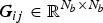 ${{\bi G}_{ij}} \in {{\rm \opf R}^{{N_b} \times {N_b}}}$ are diagonal matrices given by
 $${{\bi G}_{ij}}={\rm diag}\lpar {g_{ij}}\comma \; \cdots\comma \; {g_{ij}}\rpar \comma \;$$
with g ij being the corresponding (i, j)th entry in the G matrix in (6). Similarly,  $\bar{\bi C} \in {{\rm \opf R}^{{N_h} \times {N_h}}}$ is a block matrix
 $\bar{\bi C}=\left[{{{\bi C}_{ij}}} \right]$ representing the contribution of the linear memory elements of the network to the frequency components. The blocks
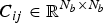 ${{\bi C}_{ij}} \in {{\rm \opf R}^{{N_b} \times {N_b}}}$ are diagonal matrices given by
 $${{\bi C}_{ij}}={c_{i\comma j}}\left[{\matrix{ 0 & 0 & 0 & \cdots & 0 & 0 \cr 0 & 0 & {{\omega _1}} & \cdots & 0 & 0 \cr 0 & { - {\omega _1}} & 0 & \cdots & 0 & 0 \cr \vdots & \vdots & \vdots & \ddots & \vdots & \vdots \cr 0 & 0 & 0 & \cdots & 0 & {{\omega _k}} \cr 0 & 0 & 0 & \cdots & { - {\omega _k}} & 0 \cr } } \right]\comma \;$$
with c ij being the corresponding entry in the C matrix in (20). Finally the matrix  $\bar{\bi S} \in {{\opf R}^{{N_h} \times {N_h}}}$ is a block matrix
 $\bar{\bi S}=\left[{{{\bi S}_{ij}}} \right]$ with each
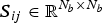 ${{\bi S}_{ij}} \in {{\rm \opf R}^{{N_b} \times {N_b}}}$ block being a diagonal matrix with the following structure
 $${{\bi S}_{ij}}={s_{i\comma j}}\left[{\matrix{ 0 & 0 & 0 & \cdots & 0 & 0 \cr 0 & { - \omega _1^2 } & 0 & \cdots & 0 & 0 \cr 0 & 0 & { - \omega _1^2 } & \cdots & 0 & 0 \cr \vdots & \vdots & \vdots & \ddots & \vdots & \vdots \cr 0 & 0 & 0 & \cdots & { - \omega _k^2 } & 0 \cr 0 & 0 & 0 & \cdots & 0 & { - \omega _k^2 } \cr } } \right]\comma \;$$
with s ij being the corresponding entry in the S matrix in (5). Note that N b varies with the number of harmonics (H) and is equal to 2H + 1.
B) Moments computation for MEMS circuits
In this section, we derive the moments computation algorithm using the new formulation given in the previous subsection. In this way, we show how to compute the moments for circuits that contain both the electrical nonlinearities associated with semiconductor circuits, in addition to the nonlinearities associated with MEMS variable capacitors. The moments expansion will be performed around the DC operating point for the same reasons that were previously discussed in Section III.
The derivation of the moments computation algorithm begins by substituting (7) into (24), which results in the following expression:
 $$\Omega \sum\limits_{k=0}^q \, {{\bi M}_k}{\alpha ^k}+\sum\limits_{k=0}^q \, {{\bi F}_k}{\alpha ^k} - {{\bi B}_{DC}} - \alpha {{\bi B}_{RF}}=0.$$
The terms Fk are the Taylor expansion coefficients of F(X) with respect to α given by:
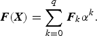 $${\bi F}\lpar {\bi X}\rpar =\sum\limits_{k=0}^q \, {{\bi F}_k}{\alpha ^k}.$$
It is useful to also express the derivative of this nonlinear vector with respect to the solution vector X (i.e. the Jacobian matrix  $\displaystyle{{\partial F\lpar X\rpar } \over {\partial X}}$) as a Taylor series expansion with respect to α as follows
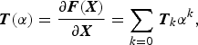 $${\bi T}\lpar \alpha \rpar =\displaystyle{{\partial {\bi F}\lpar {\bi X}\rpar } \over {\partial {\bi X}}}=\sum\limits_{k=0} \, {{\bi T}_k}{\alpha ^k}\comma \;$$
where Tn are referred to as the moments of the nonlinear Jacobian matrix. The zero moment vector, M0, is obtained by setting the value of α in (28) to zero which yields the relation:
 $$\Omega {{\bi M}_0}+{\bi F}\lpar {{\bi M}_0}\rpar ={{\bi B}_{DC}}.$$
Note that the solution to equation (31) is essentially the computation of the dc solution for the circuit, which has a relatively small computation cost. To solve for the remaining moments (Mn; n ≥ 1), coefficients of equal powers of α are equated on both sides of (28). Equating the coefficients of the first power of α results in:
 $$\Omega {{\bi M}_1}+{{\bi F}_1}={{\bi B}_{RF}}.$$
It is useful here to rewrite  ${{\bi F}_1}=\displaystyle{{\partial F} \over {\partial \alpha }}\left\vert _{\alpha=0} \right. {\rm as}\, {F_1}=\displaystyle{{\partial F} \over {\partial X}} \cdot \displaystyle{{\partial X} \over {\partial \alpha }} _{\vert \alpha=0}={{\bi T}_0}{{\bi M}_1}$. Substituting this expression into (32) then yields:
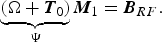 $$\underbrace {\lpar {\bf \Omega }+{{\bi T}_0}\rpar }_{\bf \Psi }{{\bi M}_1}={{\bi B}_{RF}}.$$
The first moment can now be obtained using one LU decomposition to solve (33). It is important to note that the matrix Ψ = (Ω + T0) is a sparse matrix which is already evaluated when obtaining the dc solution of the nonlinear system. Therefore, it has a similar structure to a Jacobian matrix, but is significantly more sparse. In addition, a comparison of Ψ in (33) with Φ in (10) shows that the sparsity pattern of the original moments computation matrix is preserved for systems that contain MEMS nonlinearities. To obtain the remaining moments, the coefficients of α n on both sides of (28) are equated to obtain:
 $$\Omega {{\bi M}_n}+{{\bi F}_n}=0\quad \quad n\gt 1.$$
The evaluation of Fn in (34) remains unchanged from the original moments computation algorithm described in Section III.B and is given by:
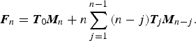 $${{\bi F}_n}={{\bi T}_0}{{\bi M}_n}+n\sum\limits_{j=1}^{n - 1} \, \lpar n - j\rpar {{\bi T}_j}{{\bi M}_{n - j}}.$$
Combining the expression in (35) with that of the relation in (34) results in the following recursive relation for computing the nth moment vector:
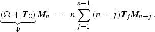 $$\underbrace {\lpar {\bf \Omega }+{{\bi T}_0}\rpar }_{\bf \Psi }{{\bi M}_n}=- n\sum\limits_{j=1}^{n - 1} \, \lpar n - j\rpar {{\bi T}_j}{{\bi M}_{n - j}}.$$
The Tj terms are as defined in (30). Note that since F(X) and X are vectors, Tj will be block matrices of the form
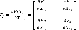 $${{\bi T}_j}=\mathop {\displaystyle{{\partial {\bi F}\lpar {\bi X}\rpar } \over {\partial {\bi X}}}}\nolimits_j=\left[{\matrix{ {\displaystyle{{\partial F1} \over {\partial X_{1j}}}} & \cdots & {\displaystyle{{\partial F1} \over {\partial X_{nj}}}} \cr \vdots & \ddots & \vdots \cr {\displaystyle{{\partial Fn} \over {\partial X_{1j}}}} & \cdots & {\displaystyle{{\partial F_n} \over {\partial X_{nj}}}} \cr } } \right]\comma \;$$
where each  $\displaystyle{{\partial F_k} \over {\partial X_i}}$ term is a matrix in itself. For example, if we consider the first block matrix
 $\displaystyle{{\partial F_1} \over {\partial X_i}}$, then each coefficient of its Taylor series expansion with respect to α is given by
 $$\displaystyle{{\partial F_1} \over {\partial X_1\, j}}={\Gamma ^{ - 1}}\left[{\matrix{ {\displaystyle{{\partial {f_1}\lpar {x_1}\lpar {t_1}\rpar \rpar } \over {\partial x_1\, \, \, \, \, \, \, \, \, \, \, \, \, \, \, \,}}}{_j} & {} & 0 \cr {} & \ddots & {} \cr 0 & {} & {\displaystyle{{\partial f_1\lpar {x_1}\lpar {t_s}\rpar \rpar } \over {\partial x_1}}}{_j} \cr } } \right]\Gamma\comma \;$$
where t 1 to t s are time sample points that are equally spaced over the fundamental period. Note that frequency mapping and truncation methods [Reference Kundert, White and Sangiovanni-Vincentelli11] are used in order to handle quasi-periodic inputs efficiently using the Fast Fourier Transform, and Γ is the Inverse Direct Fourier Transform matrix. Also note that the matrix vector multiplication with Γ can be done efficiently by taking advantage of the Fast Fourier Transform algorithm. Once evaluated, the Taylor coefficient  $\displaystyle{{\partial F1} \over {\partial X1j}}$ is entered in Tj at the location corresponding to
 $\displaystyle{{\partial F1} \over {\partial X1\, \, \, \, }}$.
From (37) and (38), it can be seen that the evaluation of the Tj matrices reduces to the evaluation of the moments for the derivatives of the nonlinear functions, i.e. the evaluation of  $\displaystyle{{\partial f\lpar x\rpar } \over {\partial x\, j}}$ for each function f and each variable x. Next, we show how these derivatives are determined for the MEMS nonlinearities.
C) Computation of the derivatives for the MEMS nonlinearities
The computation of the moments requires the computation of the coefficients of the series expansions of the partial derivatives for each of the nonlinear functions found in the nonlinear MEMS dynamical model described by (1–3) so they can be evaluated using (38). Note that the derivation of these expressions is done only once, and are then stored in the simulator to then be evaluated numerically in an efficient manner going forward.
The two primary nonlinear functions of interest are:
 $${F_1}\lpar Q\rpar =\displaystyle{{Q^2} \over {2{{\rm \epsilon }_0}A}}\comma \;$$
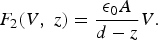 $${F_2}\lpar V\comma \; z\rpar =\displaystyle{{{{\rm \epsilon }_0}A} \over {d - z}}V.$$
Using the variable assignment of Section IV.A., these nonlinear functions can be expressed as:
 $${f_1}=\displaystyle{{x_3^2 } \over {2{{\rm \epsilon }_0}A}}\comma \;$$
 $${f_2}=\displaystyle{{{{\rm \epsilon }_0}A} \over {d - {x_2}}}{x_1}.$$
We need to determine the derivatives of these functions with respect to the variables, x 1,x 2, and x 3, in addition to the required expressions for the evaluation of their series expansion coefficients. To simplify the presentation, we define a new variable g (m,n) which is the partial derivative of function f m with respect to variable x n. With this new variable, the task at hand becomes determining the expressions required for computing each  $g_j^{\lpar m\comma n\rpar } $ term, which are the coefficients of the series expansions of g (m, n) with respect to the RF amplitude α defined as:
 $${g^{\lpar 1\comma 3\rpar }}=\displaystyle{{\partial {f_1}} \over {\partial x3}}=\displaystyle{{{x_3}} \over {{{\rm \epsilon }_0}A}}=\sum\limits_{i=0} \, g_i^{\lpar 1\comma 3\rpar } {\alpha ^i}\comma \;$$
 $${g^{\lpar 2\comma 1\rpar }}=\displaystyle{{\partial {f_2}} \over {\partial x1}}=\displaystyle{{{{\rm \epsilon }_0}A} \over {\lpar d - {x_2}\rpar }}=\sum\limits_{i=0} \, g_i^{\lpar 2\comma 1\rpar } {\alpha ^i}\comma \;$$
 $${g^{\lpar 2\comma 2\rpar }}=\displaystyle{{\partial {f_2}} \over {\partial x2}}=\displaystyle{{{{\rm \epsilon }_0}A} \over {{{\lpar d - {x_2}\rpar }^2}}}{x_1}=\sum\limits_{i=0} \, g_i^{\lpar 2\comma 2\rpar } {\alpha ^i}.$$
Note that the variables x 1(t), x 2(t), and x 3(t) can also be represented using series expansions in the time domain as:
 $${x_1}=\sum\limits_{i=0} \, m_i^{\lpar 1\rpar } {\alpha ^i}\comma \;$$
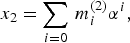 $${x_2}=\sum\limits_{i=0} \, m_i^{\lpar 2\rpar } {\alpha ^i}\comma \;$$
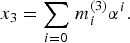 $${x_3}=\sum\limits_{i=0} \, m_i^{\lpar 3\rpar } {\alpha ^i}.$$
We begin the derivations with the first function shown in (41). A comparison of this function with its partial derivative expression given in (43) allows us to express f 1 in terms of g (1,3) and x 3 as follows:
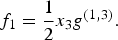 $${f_1}=\displaystyle{1 \over 2}{x_3}{g^{\lpar 1\comma 3\rpar }}.$$
Taking the derivative of (49) with respect to α then yields the expression:
 $$\displaystyle{{\partial {f_1}} \over {\partial \alpha }}=\displaystyle{1 \over 2}{g^{\lpar 1\comma 3\rpar }}\displaystyle{{\partial {x_3}} \over {\partial \alpha }}+\displaystyle{1 \over 2}\displaystyle{{\partial {g^{\lpar 1\comma 3\rpar }}} \over {\partial \alpha }}.$$
At this point, we make use of the chain rule so we can express  $\displaystyle{{\partial {f_1}} \over {\partial \alpha }}$ as:
 $$\displaystyle{{\partial {f_1}} \over {\partial \alpha }}=\displaystyle{{\partial {f_1}} \over {\partial x3}}\displaystyle{{\partial {x_3}} \over {\partial \alpha }}={g^{\lpar 1\comma 3\rpar }}\displaystyle{{\partial {x_3}} \over {\partial \alpha }}.$$
We can then substitute (51) into (50) and rearrange to obtain:
 $${g^{\lpar 1\comma 3\rpar }}\displaystyle{{\partial {x_3}} \over {\partial \alpha }}=\displaystyle{1 \over 2}{g^{\lpar 1\comma 3\rpar }}\displaystyle{{\partial {x_3}} \over {\partial \alpha }}+\displaystyle{1 \over 2}{x_3}\displaystyle{{\partial {g^{\lpar 1\comma 3\rpar }}} \over {\partial \alpha }}\comma \;$$
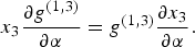 $${x_3}\displaystyle{{\partial {g^{\lpar 1\comma 3\rpar }}} \over {\partial \alpha }}={g^{\lpar 1\comma 3\rpar }}\displaystyle{{\partial {x_3}} \over {\partial \alpha }}.$$
Finally, we replace g (1,3) and x 3 in (53) with their series expansions found in (43) and in (48) to obtain:
 $$\sum\limits_{i=0} \, {m_i}{\alpha ^i}\sum\limits_{i=1} \, ig_i^{\lpar 1\comma 3\rpar } {\alpha ^{i - 1}}=\sum\limits_{i=0} \, g_i^{\lpar 1\comma 3\rpar } {\alpha ^i}\sum\limits_{i=1} \, i{m_i}{\alpha ^{i - 1}}.$$
From this expression, each  $g_j^{\lpar 1\comma 3\rpar } $ term required for the moments algorithm as given by (38) is found accordingly. The general expressions for evaluating
 $g_n^{\lpar 1\comma 3\rpar } $ are therefore:
 $$g_0^{\lpar 1\comma 3\rpar }=\displaystyle{{m_0^{\lpar 3\rpar } } \over {{{\rm \epsilon }_0}A}}\comma \;$$
 $$g_n^{\lpar 1\comma 3\rpar }=\displaystyle{1 \over {nm_0^{\lpar 3\rpar } }}\left({ng_0^{\lpar 1\comma 3\rpar } m_n^{\lpar 3\rpar }+\sum\limits_{i=1}^{n - 1} \, g_{n - i}^{\lpar 1\comma 3\rpar } m_i^{\lpar 3\rpar } \lpar 2i - n\rpar } \right).$$
A fundamentally similar procedure is followed for the second function f 2 shown in (42). The difference here is that f 2 is a function of two variables and therefore we need to determine the partial derivatives with respect to both x 1 and x 2. The relation between f 2 and the derivatives g (2,1) and g (2,2) are:
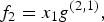 $${f_2}={x_1}{g^{\lpar 2\comma 1\rpar }}\comma \;$$
 $${f_2}=\lpar d - {x_2}\rpar {g^{\lpar 2\comma 2\rpar }}.$$
Notice that the partial derivative with respect to x 1 results in a constant term and therefore only  $g_0^{\lpar 2\comma 1\rpar } $ will be nonzero in value. As for determining the
 $g_j^{\lpar 2\comma 2\rpar } $ terms, we start by taking the derivative of (58) with respect to α which yields
 $$\displaystyle{{\partial {f_2}} \over {\partial \alpha }}=d\displaystyle{{\partial {g^{\lpar 2\comma 2\rpar }}} \over {\partial \alpha }} - \left({{g^{\lpar 2\comma 2\rpar }}\displaystyle{{\partial {x_2}} \over {\partial \alpha }}+{x_2}\displaystyle{{\partial {g^{\lpar 2\comma 2\rpar }}} \over {\partial \alpha }}} \right).$$
By once again employing the chain rule,  $\displaystyle{{\partial {f_2}} \over {\partial \alpha }}$ can be expressed as
 $$\displaystyle{{\partial {f_2}} \over {\partial \alpha }}=\displaystyle{{\partial {f_2}} \over {\partial x2}}\displaystyle{{\partial {x_2}} \over {\partial \alpha }}={g^{\lpar 2\comma 2\rpar }}\displaystyle{{\partial {x_2}} \over {\partial \alpha }}\comma \;$$
which can then be substituted into the expression of (59) to obtain:
 $$2{g^{\lpar 2\comma 2\rpar }}\displaystyle{{\partial {x_2}} \over {\partial \alpha }}=\lpar d - {x_2}\rpar \displaystyle{{\partial {g^{\lpar 2\comma 2\rpar }}} \over {\partial \alpha }}.$$
Replacing the variables x 2 and g (2,2) in (61) by their series expansions given in (45) and (47) we then obtain:
 $$\left({d - {m_i}\sum\limits_{i=0} \, {\alpha ^i}} \right)\sum\limits_{i=1} \, i{g_i}{\alpha ^{i - 1}}=2\sum\limits_{i=0} \, {g_i}{\alpha ^i}\sum\limits_{i=1} \, i{m_i}{\alpha ^{i - 1}}.$$
This relation is used to determine the individual  $g_j^{\lpar 2\comma 2\rpar } $ terms required for determining the moments, which are evaluated using:
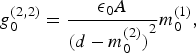 $$g_0^{\lpar 2\comma 2\rpar }=\displaystyle{{{{\rm \epsilon }_0}A} \over {{{\lpar d - m_0^{\lpar 2\rpar } \rpar }^2}}}m_0^{\lpar 1\rpar }\comma \;$$
 $$g_n^{\lpar 2\comma 2\rpar }=\displaystyle{1 \over {n\lpar d - m_0^{\lpar 2\rpar } \rpar }}\left({2ng_0^{\lpar 2\comma 2\rpar } m_n^{\lpar 2\rpar }+\sum\limits_{i=1}^{n - 1} \, g_i^{\lpar 2\comma 2\rpar } m_{n - i}^{\lpar 2\rpar } \lpar 2n - i\rpar } \right).$$
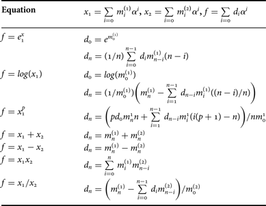
Note that the CPU cost of computing these derivatives is negligible when compared to the overall algorithm. The expressions for the derivatives are stored in the simulator along with the derivatives of other nonlinear expressions present in the circuit model, such as diode nonlinearities, MOSFET saturation current voltage relations and others. Note that a summary of the relations to determine the moment expansions of common standard functions present in most nonlinear expressions is provided in Table 2 [Reference Griffith and Nakhla25].
Formulas for derivatives of standard functions.
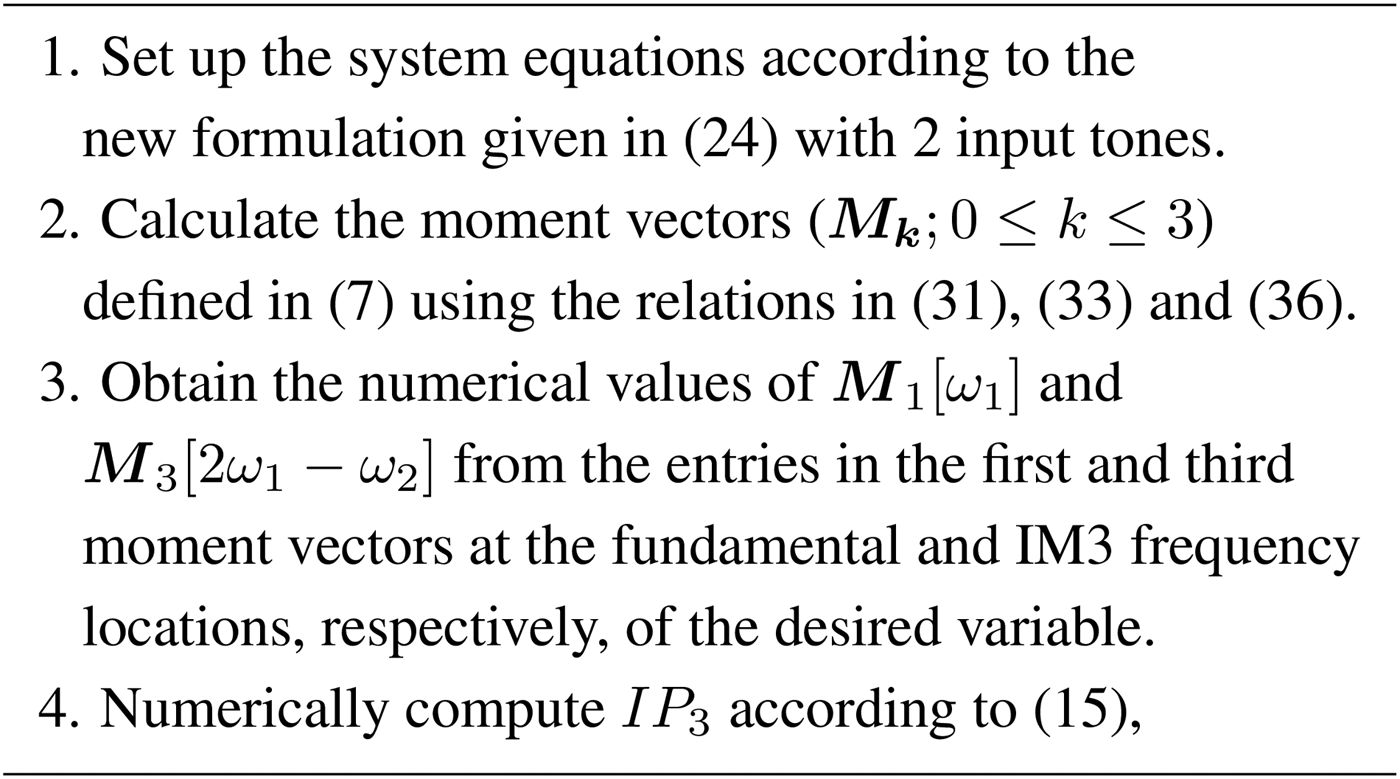
Finally, we remind the reader that once the moment vectors have been evaluated, the computation of a figure of merit like IP 3 is accomplished according to the relation given by (15) using the values of numerical entries at specific locations in the moments which we have now shown how to compute. A summary of the main steps of the algorithm is given in Fig. 3.
Summary of the IP 3 computation algorithm using moments.
D) Effect of using a more refined MEMS model
In this paper, we have developed the proposed moments method for efficient distortion analysis of circuits containing MEMS variable capacitors on the basis of the simplified 1-D MEMS model that was presented in Section II. For studying intermodulation distortion in addition to the effects of Q and V on the dynamic response of MEMS switches, the 1-D model works well and provides a lot of useful information. The simplified model, however, has its limitations. For a more accurate analysis of intermodulation distortion in addition to other phenomena, such as pull-down, power handling and noise, more refined models can be used. These refinements can include, for example, an expression that accounts for the nonlinear behavior of the spring in the mass–spring–damper model [Reference Innocent, Wambacq, Donnay, Tilmans, Sansen and Man8]. Another modification can be made to include the effects of the contact force, F c, between the moving plate and the dielectric layer, in addition to the electrostatic force [Reference Rebeiz3]. Similarly, we can also include a general nonlinear expression to more accurately describe the value of the damping coefficient, b, in the refined model [Reference Bao, Yang, Sun and French26]. These additional refinements would come at the expense of additional model complexities, which will mainly appear when determining the additional expressions for the derivatives of the MEMS nonlinearities required to compute the moments. This can be accomplished with the aid of Table 2 for most nonlinear expressions, with the resulting derivatives stored in the simulator as part of the device model.
If the additional expressions in the refined models are only functions of the existing variables in the formulation, the computation time of the proposed moments method will not be significantly affected since the size of the system formulation will remain the same. On the other hand, if new variables are introduced, though the computation time will increase, this will also be equally the case with the reference harmonic balance method since both approaches are based on similar formulations, thereby preserving the CPU cost advantage of the proposed method.
V. EXAMPLE APPLICATION: LC TANK
In this section, the numerical results of simulations performed on an example circuit using the proposed moments approach are benchmarked and compared with the results of the harmonic balance approach to demonstrate the efficiency of the new method. Note that the results of the harmonic balance simulations provide a good reference point for our method since harmonic balance simulations of circuits with RF MEMS-based variable capacitors have been compared with measurements on several occasions in the literature [Reference Rizzoli, Gaddi, Iannacci, Masotti and Mastri13, Reference Veijola15].
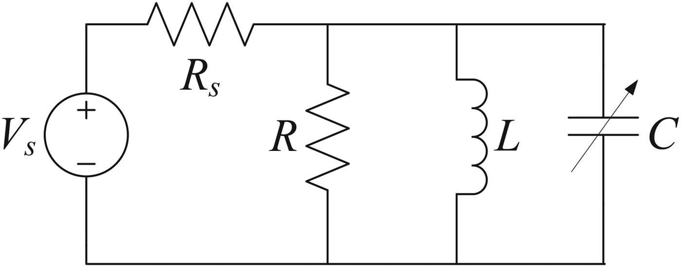
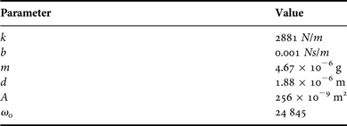
The example circuit which we will consider in detail is a tunable LC tank (also referred to as a LC section) with a variable capacitor that can be used to implement tunable RF filters [Reference Innocent, Wambacq, Donnay, Tilmans, Sansen and Man8]. To test the moments-based method, we will consider a linear inductor and a nonlinear MEMS variable capacitor as illustrated in Fig. 4. The model parameters used in the simulation are listed in Table 3 and are based on the MEMS design described in [Reference Innocent, Wambacq, Donnay, Tilmans, Sansen and Man8].
Parallel LC tank implemented.
Model parameters for the MEMS variable capacitor in the example circuit.
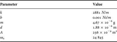
The circuit is simulated using two input tones of 1 dBm power, with a fixed frequency spacing of 1 KHz and varying average frequencies in the range of 10 KHz–1 MHz. Note that since the moments method is based on the same extended system formulation as that used in a full harmonic balance simulation, the accuracy of the numerical results of both methods, when compared to lab measurements, are expected to be similar, with the moments method providing a clear and significant saving in CPU cost. A prototype MATLAB simulator is used to test the circuit using both approaches on a workstation running a dual-core Intel Core i5 processor with 6 GB of system RAM.
Using our prototype MATLAB simulator, the computation time of a single harmonic balance simulation with 9 harmonics was 3.85 s. On the other hand, the moments method was completed in only 1.88 s. This represents a speed-up of around 2.1 times. With these results in mind, it is important at this point to give some insight on the main reasons behind the observed speedup, and how it could vary depending on the type of circuit and the simulation variables selected.
− The sparsity difference between the harmonic balance Jacobian matrix and the moments computation matrix used in the new approach, is a key factor in the reduced CPU cost of the new approach. As illustrated in the sparsity patterns of the two matrices shown in Figs 5 and 6, the harmonic balance Jacobian contains several dense blocks, while those same blocks are significantly sparser in the moments matrix since the derivatives are evaluated at dc. As a result, the moments matrix has a significantly smaller number of non-zeros even though both matrices are of equal dimensions.
Fig. 5.Sparsity pattern of the harmonic balance Jacobian.
Fig. 6.Sparsity pattern of the moments matrix.
− The minimum number of harmonics that must be accounted for to perform the simulation is 3 (due to the need to compute IP 3). However, for more accurate results using harmonic balance, a greater number of harmonics should be accounted for in the simulation, which would come at the expense of a greater number of variables in the equations. The moments method presents greater speedup when a higher number of variables are present in the formulation. A comparison of the computation times for this example circuit shows that the speedup does indeed increase when higher harmonics are taken into account, as shown in Fig. 7.
Fig. 7.Effect of number of harmonics on computation times.
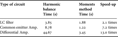
− This example LC tank circuit is a relatively small one in size and simple in complexity. Having a larger circuit with more unknown variables and more nonlinear components would result in a greater speedup for the proposed method. This is clearly illustrated when we compare the computation times of both approaches in more complex RF circuit topologies as shown in Table 4 [Reference Tannir and Khazaka27].
Table 4.Computation cost comparison of finding the IP3 of different RF circuits.
− It is common for harmonic balance solvers to take more iterations to converge for different circuit topologies, especially ones with MEMS nonlinearities. In fact, convergence of the harmonic balance simulation is one of the major challenges in the presence of MEMS variable capacitors, as highlighted in [Reference Rizzoli, Gaddi, Iannacci, Masotti and Mastri13]. The moments method, on the other hand, will always run to completion in the same number of steps due to the direct nature of the algorithm with no need to apply iterative methods such as Newton iteration or the Generalized Minimum Residual (GMRES) approach. In the case more iterations are required for the harmonic balance method to converge, the speedup of the moments method will be even greater.
In order to verify the accuracy of the moments method, a direct comparison of the expected numerical results obtained using the moments approach with those obtained using harmonic balance was made. In this circuit, the value of IP 3 is proportional to both the biasing voltage and the frequencies of the applied tones (both the average frequency and the tone difference). The simulations were performed with the bias voltage much smaller than the pull-in voltage of the MEMS capacitor, which is found using [Reference Innocent, Wambacq, Donnay, Tilmans, Sansen and Man8]:
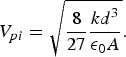 $${V_{pi}}=\sqrt {\displaystyle{8 \over {27}}\displaystyle{{k{d^3}} \over {{{\rm \epsilon }_0}A}}} .$$
In Fig. 8, a comparison is shown for the expected IP 3 values computed for the circuit with varying input frequency tones relative to the resonant frequency ω 0. Note that the frequency spacing between the tones was kept the same at 1 KHz. As can be seen from the plot, the results are projected to track the results of the harmonic balance approach very well.
Comparison of IP3 value.
VI. CONCLUSION
In this paper, the moments based method for efficient distortion analysis was extended to cover a new class of circuits that includes RF MEMS variable capacitor devices. It was shown that by including the membrane displacement as an additional variable in the extended formulation, the sparsity pattern of the moments computation matrix is not affected. The method does not require finding the steady-state solution of the system in order to compute its third-order intercept point. The computation cost of the moments method is of the order of a solution of a sparse set of linear equations.
ACKNOWLEDGEMENTs
This work was supported by the School of Engineering at the Lebanese American University.
Dani A. Tannir received his Bachelor of Engineering degree (with distinction) in Electrical Engineering from the American University of Beirut, Beirut, Lebanon in 2004. He then received his Master's and Ph.D. degrees in Electrical Engineering from McGill University, Montreal, Canada in 2006 and in 2010, respectively. He was named on the Dean's Honor list for his Master's thesis work, and was the recipient of several awards during his Ph.D. studies, including the Alexander Graham Bell Canada Graduate Scholarship from the Natural Sciences and Engineering Research Council of Canada. Dr. Tannir joined the Department of Electrical and Computer Engineering at the Lebanese American University in 2011, where he is currently working as an Assistant Professor. His research interests include the development of algorithms and techniques for the efficient simulation of nonlinear analog and RF integrated circuits.