
In a recent work,[Reference Gayle and Cook1] the experimental application of a time-dependent indentation model was demonstrated in determining the viscous, elastic, and plastic properties of polymer and polymer-composite materials. Earlier indentation work concerned ex situ time-independent measurements, first of the plastic properties of materials via the hardness,[Reference Tabor2] primarily metals, and later including the elastic properties via the modulus,[Reference Lawn and Howes3] primarily of ceramics. In the last few decades, in situ time-independent instrumented indentation methods have been developed to measure the hardness and modulus in a single test.[Reference Oliver and Pharr4] The recent work also used instrumented indentation methods and extended the testing and analysis to include the measurement of viscous properties of materials,[Reference Gayle and Cook1] primarily polymers.
Although the recent work had all the advantages of indentation testing—small sample volumes, minimal sample preparation, ability to map areas—the measurement of a third parameter (the viscous response) led to somewhat complicated testing protocols and analysis. The general complication is inevitable given the historical development in indentation testing sophistication, from single-parameter plastic properties[Reference Tabor2] to two-parameter elastic and plastic properties[Reference Lawn and Howes3, Reference Oliver and Pharr4] to three, or more, parameters for viscous, elastic, and plastic properties.[Reference Gayle and Cook1] A large part of the complication of the most recent work was the development of analytical solutions to the model equations. Such solutions were necessary in order to join different experimental indentation loading segments together by boundary-condition matching and accomplish the “reverse” modeling process of fitting experimental measurements to the model. Although the methods were very successful in predicting properties and behavior, the complications obscured the simplicity of the model and detracted from the ability of the model to explain commonly observed time-dependent indentation phenomena. Here, we redress some of the complications and use the model in a “forward” mode by predicting the behavior for materials of known properties undergoing commonly encountered indentation sequences. The behavior is predicted using simply-implemented numerical integration, doing away with the complications of the analytical solutions. The behavior presented here should enable many “what gives rise to that?” questions to be answered for experimental observations and, in addition, provide a basis for simpler model fitting. The range of behavior—presented as typically observed load–displacement plots—demonstrates the flexibility of the model and introduces a new way of examining indentation data.
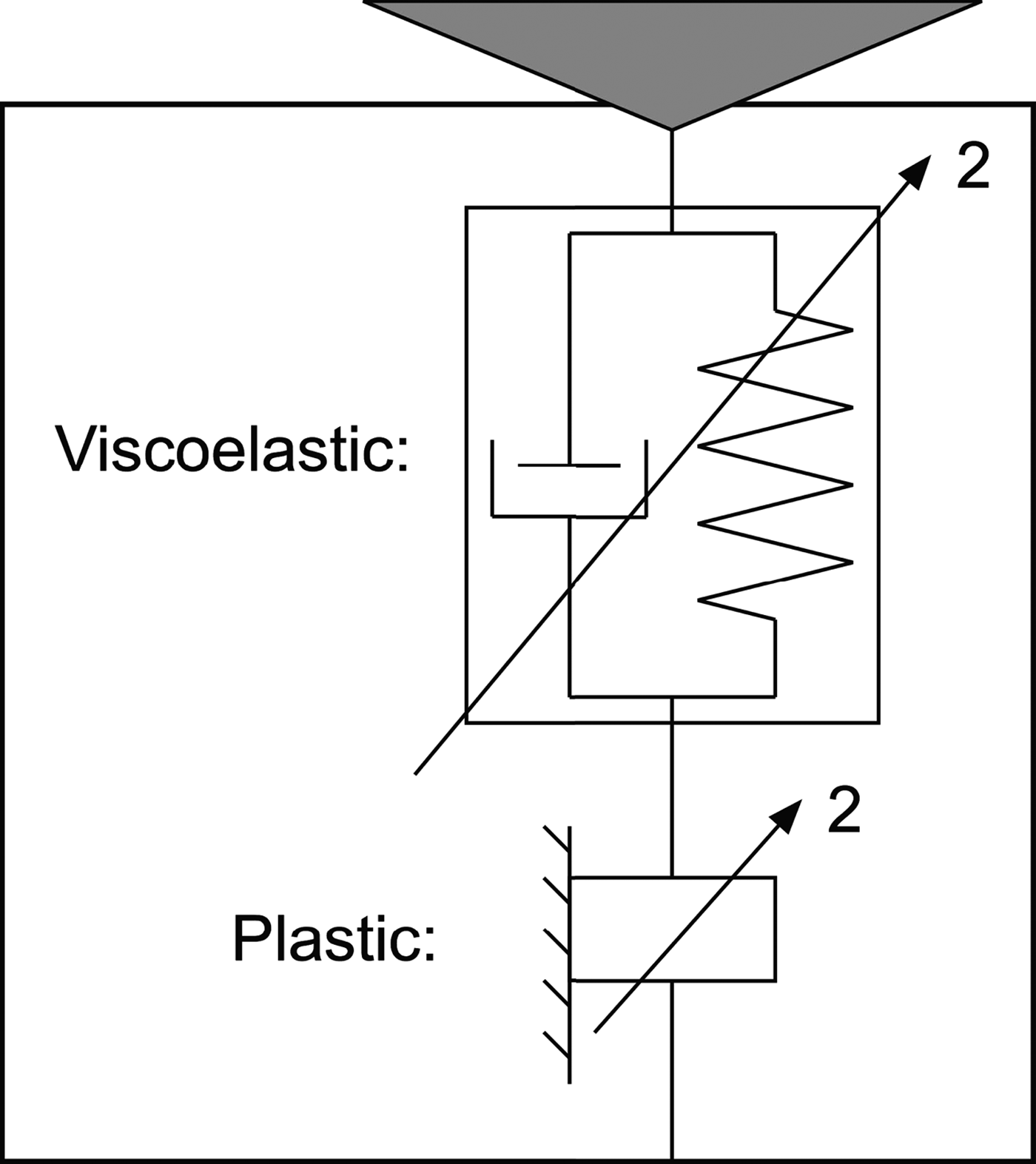
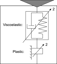
A schematic diagram of the time-dependent indentation model is shown in Fig. 1. The model consists of two elements in series: a “Kelvin”-like viscoelastic element and a plastic element. Both elements are non-linear with quadratic behavior superposed on the relationships between load, P, and displacement, h, reflecting geometrically similar indentation by a pyramid or cone (both P and h are taken as positive in indentation coordinates when directed into the material). A single viscoelastic element is used here for illustration purposes (two or more might be required to completely describe a material response[Reference Gayle and Cook1]). The total displacement as a function of time, t, beginning at the start of the indentation event with t = 0, is
 $$\eqalign{h(t) & = [P_{\max} (t)/\alpha _1 H]^{1/2} \cr & \quad + e^{ - t/\tau} \int_0^t {e^{u/\tau} [P(u)/\alpha _2 M\tau ^2 ]^{1/2} {\rm d}u},}$$
where u is a dummy variable for time.[Reference Gayle and Cook1] (Non-geometrically similar indentations, e.g., by spheres or paraboloids, lead to similar two-term displacements as Eq. (1), but the details of the terms are different.) The first term represents the plastic displacement, and the second term represents the viscoelastic displacement; both terms reflect the effects of the imposed load history. In the first term, P max(t) is the maximum load experienced over the time interval t, α 1 is a dimensionless indenter geometry constant, and H is the resistance to plastic deformation. For an elastic-perfectly plastic material, H is the hardness. In the second term, α 2 is another dimensionless indenter geometry constant, M is the resistance to viscoelastic deformation, and τ is the time constant for viscoelastic deformation (time-dependent flow). The term α 2M τ 2 is an effective quadratic viscosity; for an elastic material, M is the indentation modulus. Equation (1) is simply evaluated numerically, including the integral, and this is the approach used here: specify the imposed loading sequence P(t), calculate the resultant displacement h(t), and then eliminate time as a parameter to arrive at the resulting load–displacement response P(h). Prior work[Reference Gayle and Cook1] applied a variation of Eq. (1) to a set of common commercial polymers and determined average values of α 1 ≈ 100 and α 2 ≈ 6 and these are the values use here. (In purely plastic[Reference Tabor2] or elastic[Reference Lawn and Howes3] indentation, α 1 and α 2 are related to the effective included angle of the indenter, which is inversely related to the characteristic strain generated beneath a contact. For mixed deformation, either elastic–plastic[Reference Oliver and Pharr4] or, as here, viscoelastic–plastic, α 1 and α 2 must be treated as adjustables that are consistent with other measurements, e.g., hardness, modulus[Reference Gayle and Cook1].) The effects of the values of the material properties H and M and of the loading sequence P(t) are to be explored.
Schematic diagram of the viscous–elastic–plastic pyramidal indentation model, consisting of a quadratic viscoelastic Kelvin element in series with a quadratic plastic element.

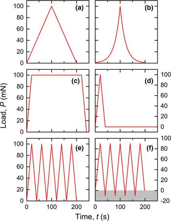
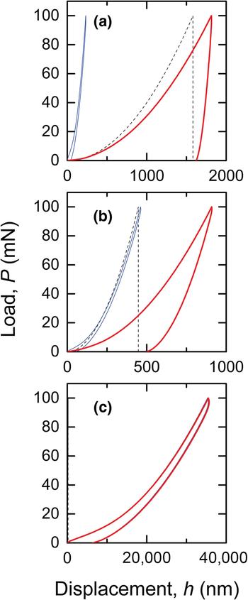
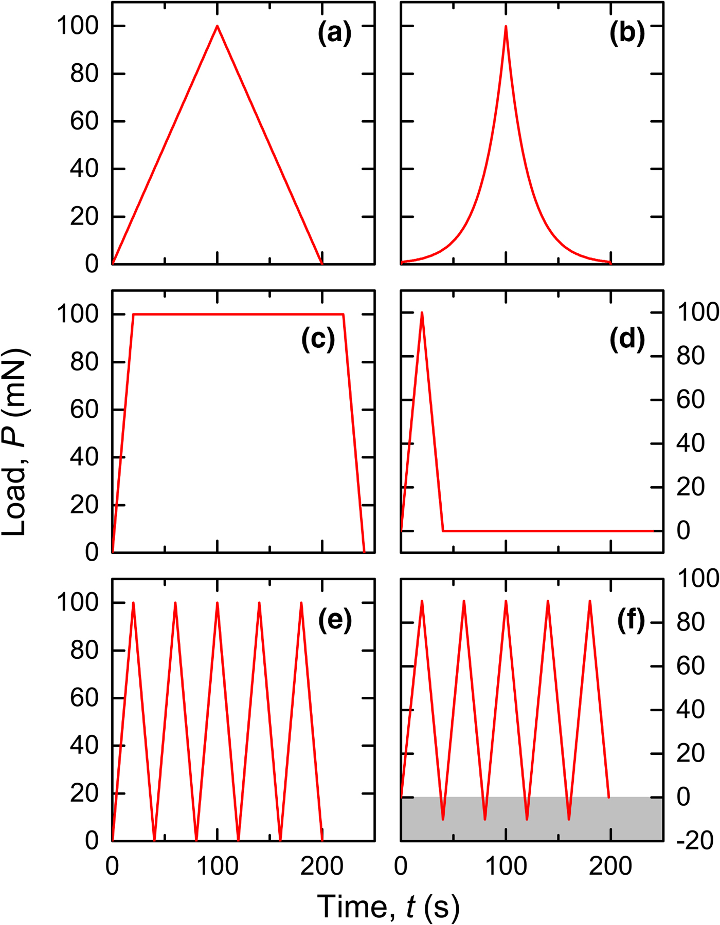
Figure 2 shows the loading sequences examined, including single loading and unloading ramps [Figs. 2(a) and 2(b)], load holds [Figs. 2(c) and 2(d)], and cyclic loads [Figs. 2(e) and 2(f)] (characteristic peak loads are 100 mN and test times are 200 s). Figure 3 demonstrates the flexibility of the model in predicting the P(h) responses resulting from imposing the very simple and common triangular P(t) load spectrum of Fig. 2(a) on materials with minimally time-dependent properties (τ = 4 s in all responses in Fig. 3). The dashed lines represent the plastic responses and increases non-linearly with displacement before reaching maximum values at peak load (at t = 100 s) and then remaining invariant. The fine solid lines represent the largely elastic responses, which also increase with time before reaching maximum values at peak load and then decreasing to almost zero. The bold solid lines represent the total material responses and are the sums of the two individual responses and also pass through maxima. Figure 3(a) represents typical metallic behavior (using H = 0.4 GPa and M = 300 GPa) in which the plastic response is dominant and there is little recovery.[Reference Tabor2] Figure 3(b) represents typical ceramic behavior (H = 5 GPa, M = 80 GPa) in which the elastic and plastic responses are approximately equal and there is significant recovery.[Reference Lawn and Howes3] Figure 3(c) represents typical elastomer behavior (H = 20 GPa, M = 0.013 GPa) in which the elastic response is dominant and there is almost complete recovery.[Reference Cook and Oyen5]
Indentation load–time sequences examined. (a) Single linear load and unload triangle. (b) Single exponential load and unload. (c) Trapezoid with peak-load hold. (d) Triangle followed by zero-load hold. (e) Five cyclic triangles. (f) Five cyclic triangles including small negative loads (shaded) associated with adhesion. Loads and times are to scale.
Indentation load–displacement responses showing the plastic components (dashed lines), the viscoelastic components (fine solid lines), and the full summed responses (bold solid lines) for the imposed load spectrum of Fig. 2(a). The responses include minimal time dependence associated with indentation of (a) a metal, (b) a ceramic, and (c) an elastomer (plastic component is negligible).
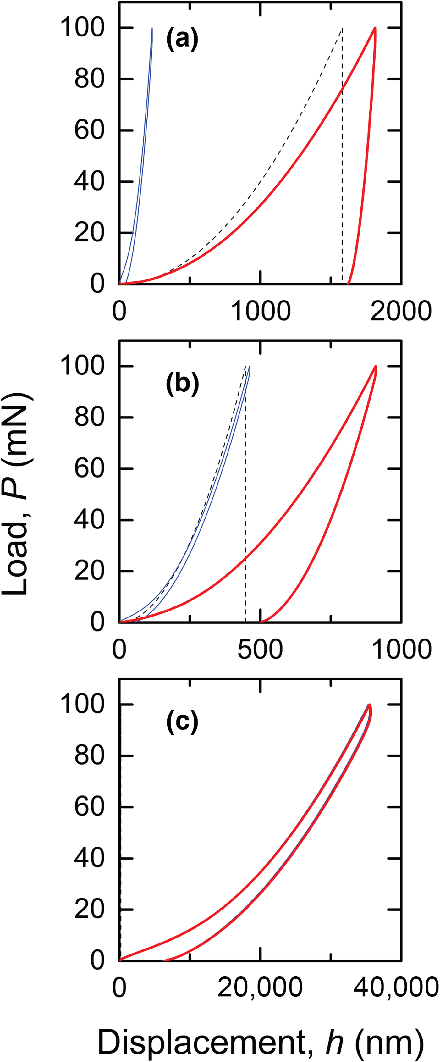
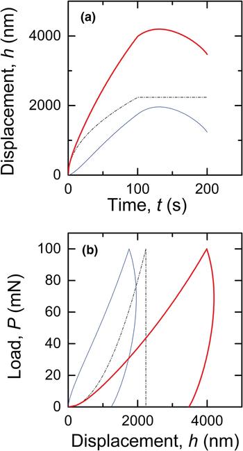
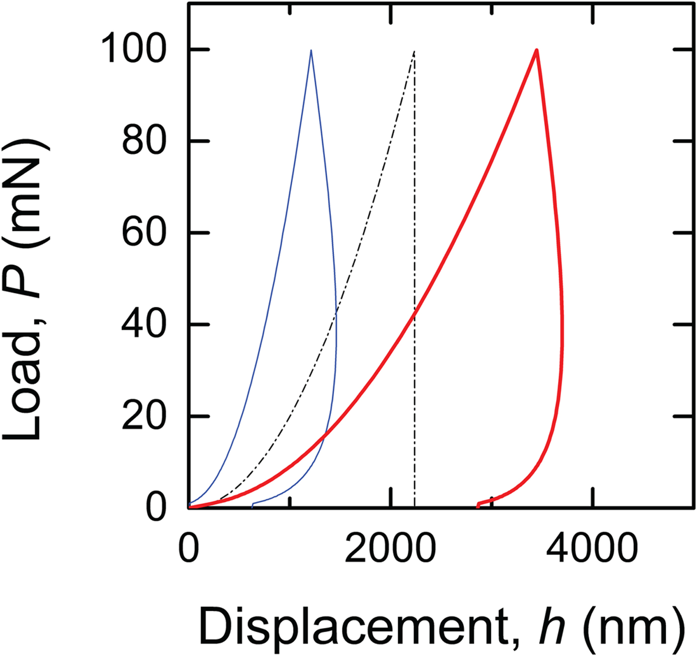
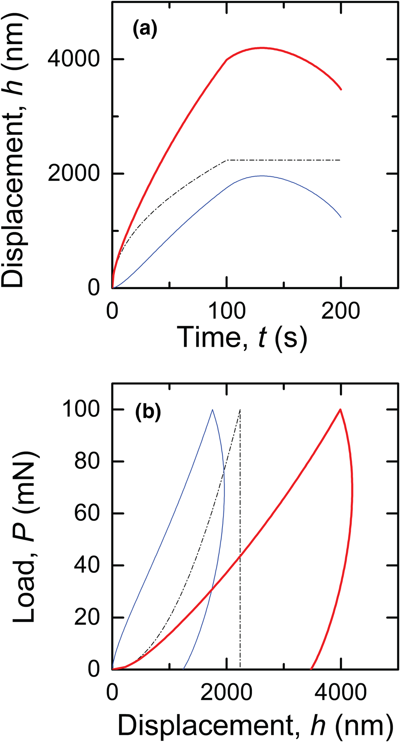
Figure 4 shows the responses resulting from imposing the triangular P(t) load spectrum of Fig. 2(a) on a typical viscoelastic–plastic material such as a glassy polymer [using H = 0.2 GPa, M = 3 GPa, and τ = 40 s, similar to poly(methyl methacrylate), PMMA[Reference Gayle and Cook1]]. The dot-dashed lines represent the plastic response, which will be common throughout and provides a convenient reference. The fine solid lines represent the viscoelastic response, which increases with time before passing through a maximum value after peak load and then decreasing to a non-zero value. The bold solid lines represent the total material responses. The h(t) responses in Fig. 4(a) are the most convenient representation of data when time effects are to be analyzed[Reference Gayle and Cook1, Reference Cook and Oyen5] and clearly display the differences between the responses. However, the more common representation of indentation data is to eliminate time as a parameter between Figs. 2(a) and 4(a) to arrive at the P(h) responses [Fig. 4(b)]. A new way of examining indentation data is shown in Fig. 4(b), which emphasizes the P(h) hysteresis generated by both responses and indicates the “perturbation” of the underlying plastic response by the viscoelastic response to yield the full behavior. The comparable magnitudes of the elastic displacement, the viscous loss, and the plastic loss in Fig. 4(b) exemplify a viscous–elastic–plastic material: The full response exhibits a typical polymeric hysteretic indentation curve characterized by a marginally curved loading response and an initial negative tangent on unloading followed by eventual recovery, giving rise to the typical forward-going “nose.”
Indentation (a) displacement–time and (b) load–displacement responses showing the plastic components (dot-dashed lines), the viscoelastic components (fine solid lines), and the full summed responses (bold solid lines) for the imposed load spectrum of Fig. 2(a). The responses exhibit time dependence associated with indentation of a typical glassy polymer, including the forward-going “nose” during unloading.
To emphasize the time dependence, Fig. 5 plots the P(h) responses for the same PMMA-like parameters used above [using the same notation as Fig. 4(b)], but imposing the exponential loading ramp of Fig. 2(b) [such a ramp results from maintaining  $\dot P/P = const.$, leading to P ~ Aexp(Bt)]. As the peak load is unaltered from Fig. 2(a), the plastic P(h) response (dot-dashed line) is unaltered from Fig. 4(b). The viscoelastic response (fine line) is completely altered, however, reflecting a much greater time at smaller loads [compare Figs. 2(a) and 2(b)] and therefore smaller overall displacement and less hysteresis. The full response (bold line) in Fig. 5 is markedly different from that in Fig. 4(b), with a nose at smaller load and greater recovery.
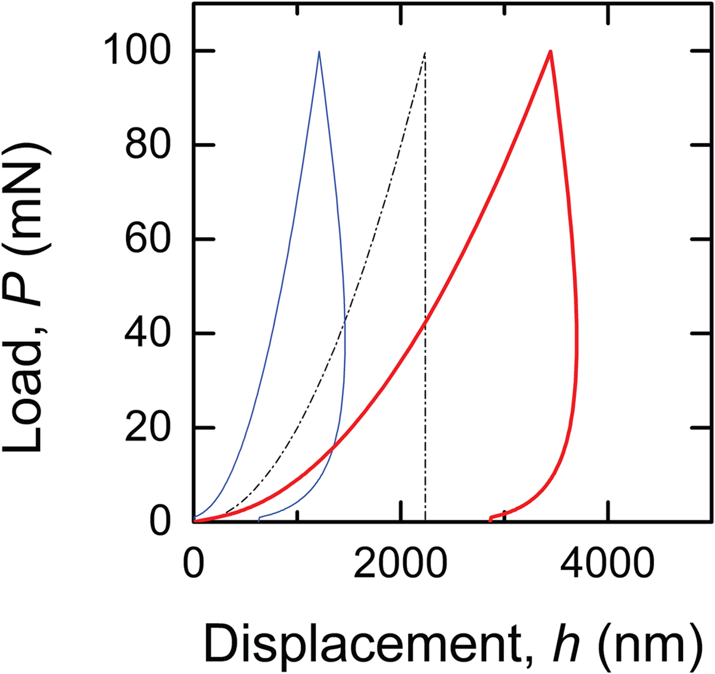
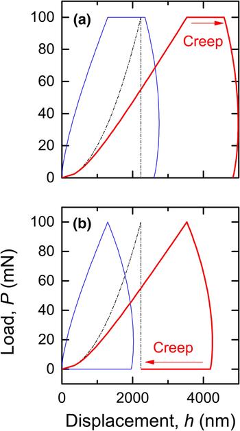
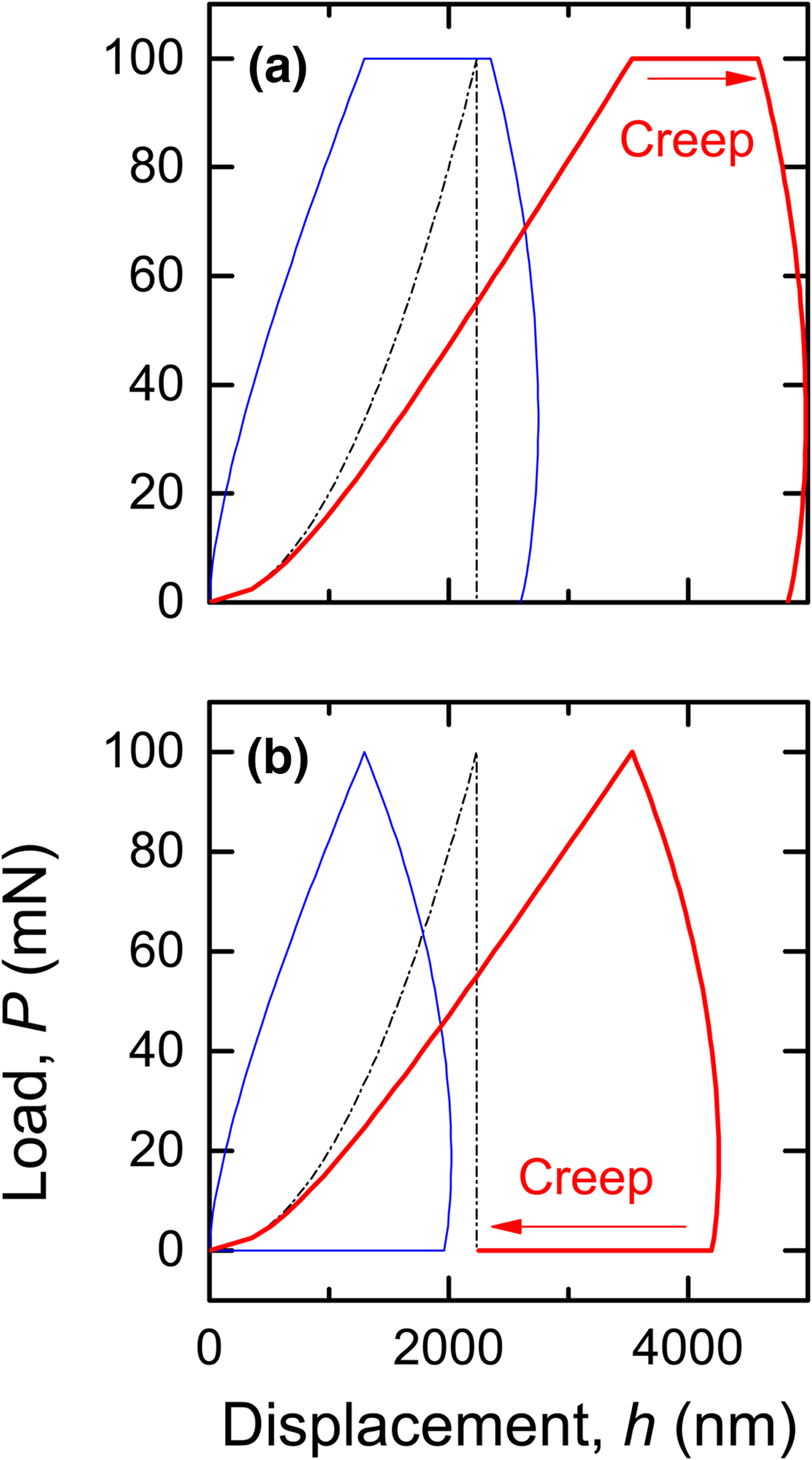
Figure 6 plots the P(h) responses for the same PMMA-like parameters used above [using the same notation as Fig. 4(b)], but imposing the load hold sequences of Figs. 2(c) and 2(d). Once again, as the peak load is unaltered from Fig. 2(a), the plastic P(h) responses (dot-dashed lines) are unaltered from Figs. 4(b) and 5. The viscoelastic responses are dramatically altered from those of Figs. 4(b) and 5 by the speeding-up of the load ramps and the inclusion of the load holds, leading to clear differences in the full responses. In the first case [Fig. 6(a)], the load hold is inserted at peak load, prior to unloading, leading to forward-going indentation creep at peak load (indicated by the arrow); there is some displacement and recovery during unloading. In the second case [Fig. 6(b)], the load hold is inserted at zero load, after unloading, leading to backwards-going creep at zero load (“creep recovery,” also indicated by an arrow); there was forward displacement but little recovery during unloading. The creep segments in both curves, although of opposite signs, are of comparable magnitudes. The full hysteresis loop is much greater in size in the first case than in the second, and the final displacement in the first case includes both plastic and viscoelastic displacement (about 5000 nm here). In the second case, the viscoelastic displacement recovers to almost zero in the creep segment, leading to a final displacement that is almost completely plastic (about 2000 nm here). Comparison of Figs. 6(a) and 6(b) emphasizes the importance of the details of the time history of loading in determining the final indentation dimensions. In particular, Fig. 6(b) makes clear that ex situ measurements of impression dimensions after indentation (as in a typical experiment) will depend on the creep recovery time.
Indentation load–displacement responses for the imposed load-hold spectra of Figs. 2(c) and 2(d) on a glassy polymer. Notation as in Fig. 4. (a) Load-hold at peak load exhibiting forward creep. (b) Load-hold at zero load exhibiting backward creep.
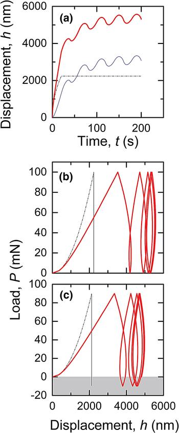
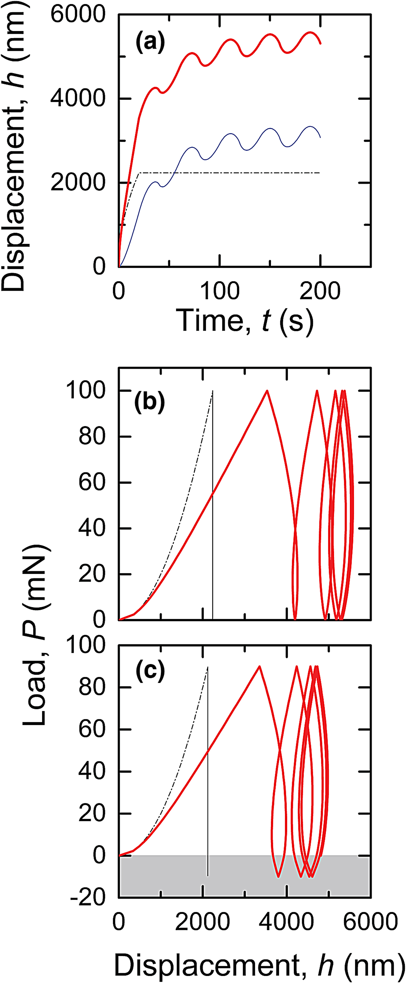
Figures 7(a) and 7(b) plot the h(t) and P(h) responses, respectively, for the same PMMA-like parameters used above [using the same notation as Fig. 4(b)], but imposing the cyclic load sequence of Fig. 2(e). As the peak load is unaltered from Fig. 2(a), the plastic P(h) responses (dot-dashed lines) are unaltered from Figs. 4(b), 5, and 6. The viscoelastic responses are altered dramatically by the inclusion of the cyclic load, leading to clear differences in the full responses from those of Figs. 4, 5, and 6. The h(t) response in Fig. 7(a) shows oscillations superposed on an increasing background, associated with cyclic loading about a non-zero mean load, leading to the hysteretic, increasing displacement, cyclic P(h) response of Fig. 7(b) (the viscoelastic component is omitted for clarity). A steady-state hysteresis loop (centered on about 5200 nm) is beginning to appear in Fig. 7(b). The cyclic sequences in Figs. 2(e) and 2(f) have the same amplitude (100 mN), but differ in mean level such that the cycles of Fig. 2(e) are all positive and those of Fig. 2(f) include negative loads (to −10 mN); the negative loads are indicated by the shaded region and are supported by adhesion between the indenter and sample. The negative loads were handled numerically by replacing [P(u)]1/2 in Eq. (1) with sgn(P)[|P(u)|]1/2 (sgn is the sign function) leading to negative viscoelastic displacement rates for negative loads; the integral and Eq. (1) were otherwise unchanged. The resulting h(t) behavior for the 2(f) sequence is similar to that for the 2(e) sequence and is not shown. The P(h) behavior for the 2(e) sequence is slightly different, however, and is shown in Fig. 7(c). As the peak load is slightly diminished, the plastic P(h) response (dot-dashed line) is slightly reduced. However, the inclusion of the negative load [also shown in Fig. 7(c) by a shaded band] alters the full behavior, including the viscoelastic response, in two ways: First, the displacements are smaller, reflecting the smaller loads and negative displacements [the steady-state hysteresis loop in Fig. 7(c) is centered at 4500 nm]; and second, the hysteresis loops are larger, reflecting the negative displacements.
Indentation (a) displacement–time and (b) load–displacement responses for the imposed cyclic load spectrum of Fig. 2(e) on a glassy polymer. Notation as in Fig. 4. Note the tendency toward a steady-state hysteresis loop in the load-displacement response. (c) Load–displacement responses for the imposed cyclic load spectrum of Fig. 2(f) including a small negative adhesive load (shaded). Note the shifted, broadened steady-state hysteresis loop.
Conclusion
The time-dependent deformation model examined here [Fig. (1), Eq. (1)] can describe the combined viscous, elastic, and plastic indentation behaviors of most materials. The typical pyramidal indentation responses of metals, ceramics, polymers, and elastomers were all simply described by a single equation, and time-dependent polymeric responses were examined in detail as a function of imposed load spectra. Many different forms of indentation load–displacement responses were generated and presented in a simple scheme [e.g., Fig. 4(b)] that allows the perturbation of the plastic response by the viscoelastic response to be easily visualized. The form of minimally time-dependent indentation responses is controlled by the ratio of the plastic and viscoelastic deformation resistances, H/M. These responses are altered, sometimes significantly, by the ratio of the viscoelastic time constant to the test time, τ/t. Load ramps, holds, and cycles were all examined for typical viscous–elastic–plastic polymeric indentation conditions in which both these ratios were approximately one. Negative indentation loading was introduced to account for adhesive effects between the indenter and the sample (similar to that for the “DMT” model, in which the contact geometry is not altered by adhesive effects[Reference Maugis6]). The formulation provides a simple, flexible method of interpreting indentation load–displacement observations.