I. INTRODUCTION
Efficient solar energy conversion for hydrogen production via photoelectrochemical (PEC) water splitting has been considered as one of the most promising approaches to solving the world energy crisis. The PEC process utilizes solar energy to excite a semiconductor to generate electrons and holes, which transfer to cathodes and anodes for water splitting into hydrogen and oxygen. Although the concept is simple, the main challenge is to search for a semiconductor material as a photoelectrode to absorb enough solar energy to drive this water splitting reaction. As a ideal candidate photoelectrode, the main requirements include: (i) excellent light or solar absorption, (ii) fast charge carrier transport, (iii) suitable band structure for water reduction and/or oxidation, (iv) abundant and low cost, and (v) good chemical and photochemical stability. Since the pioneer report on photoinduced water splitting using TiO2 photoanodes, Reference Fujishima and Honda1 significant advances in PEC water splitting by semiconductor photoelectrodes have been achieved in the past few decades. Reference Chen, Shen, Guo and Mao2–Reference Shen and Mao6 Despite these advances and numerous photoelectrodes developed, there is still no single semiconductor that satisfies all the criteria for its use in the PEC water splitting system by meeting the required performance benchmarks for efficiency, durability, and cost.
A. Why hematite?
Compared to other semiconductors, hematite, the “rust,” has many potential advantages for PEC water splitting, with a favorable combination of good chemical stability, visible-light absorption, nontoxicity, abundance, and low cost. With a band energy gap of 2.1 eV and valence band edge substantially lower than the water oxidation potential, hematite turns to be a promising photoanode material for PEC water splitting, and can theoretically produce water oxidation photocurrent densities as high as 12.6 mA/cm2 under AM 1.5G solar irradiation, Reference Chen, Jaramillo, Deutsch, Kleiman-Shwarsctein, Forman, Gaillard, Garland, Takanabe, Heske, Sunkara, McFarland, Domen, Miller, Turner and Dinh7 with a maximum solar energy conversion efficiency achieving 15.5% in an ideal tandem PEC configuration. Reference Brillet, Cornuz, Le Formal, Yum, Grätzel and Sivula8 However, several key factors have greatly limited the water oxidation activity of hematite, Reference Sartoretti, Ulmann, Alexander, Augustynski and Weidenkaff9–Reference Dare-Edwards, Goodenough, Hamnett and Trevellick13 including relatively poor conductivity, high charge recombination rates, poor oxygen evolution reaction kinetics, short hole diffusion length (2–4 nm). To date, a variety of rational strategies has been devised to overcome hematite's limitation toward efficient solar water splitting, Reference Sivula, Formal and Grätzel14,Reference Katz, Riha, Jeong, Martinson, Farha and Hupp15 for instance, reducing bulk recombination by developing nanostructured architectures, improving conductivity and promoting charge transfer ability by metal ion doping, and improving water oxidation kinetics using catalysts, etc. Though the highest PEC efficiency achieved so far is still far from the theoretical limit, the photocurrent densities for water oxidation using hematite photoanodes have been greatly enhanced by several orders of magnitude. We believe that continued research will lead to revolutionary advancements which enable hematite to practical utilization for efficient PEC water splitting systems.
B. Why this review article?
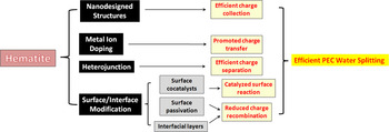
Along with the great strides of performance improvement and fundamental understanding of water oxidation with hematite electrodes, excellent review articles have been published to briefly summarize the rational fashion of technological application of hematite photoelectrodes and prospect for efficient PEC water splitting at the advanced level. Reference Sivula, Formal and Grätzel14–Reference Hamann18 Sivula et al. Reference Sivula, Formal and Grätzel14 examined basic material properties and presented recent progress on morphology control and surface treatments of hematite photoanodes as well as some advanced characterization techniques, particularly electrochemical impedance spectroscopy. Katz et al. Reference Katz, Riha, Jeong, Martinson, Farha and Hupp15 gave an all-sided but very brief review on the recent progress of PEC water splitting using hematite. Other typical review articles were focused on some specific aspects of hematite photoanodes, such as charge carrier dynamics, Reference Wheeler, Wang, Ling, Li and Zhang16 hematite obtained by hydrothermal treatment and functionalized with phycocyanin, Reference Bora, Braun and Constable17 fundamental issues and related progress. Reference Hamann18 In this review, we scheme the precise modification approaches to enhancing the performance of PEC water splitting using hematite photoelectrodes (Fig. 1) and also recent progress enhancing the hematite's photoactivity is presented in detail. Together with our thorough review of encouraging results from recent reports on hematite-based PEC water splitting, we hope to update, bridge, and inspire chemists, material scientists, and even engineers to solve the energy problem through solar hydrogen conversion, with a view of providing a good reference and inspiring new ideas for tackling this important challenge.
Schematic of modification approaches to enhancing the performance of PEC water splitting using hematite photoelectrodes.

II. NANODESIGNED STRUCTURES IMPROVING CHARGE COLLECTION
It has been widely accepted that nanostructured architectures play a very important role in the photoeletrochemical efficiency for water splitting, by determining the collection efficiency of photogenerated charge carriers. In general, short collection distance, except for long lifetime and slow recombination rate, of photogenerated charge carriers are necessary for high efficiency charge collection and PEC performance. However, a large absorption depth in the visible region, required by hematite's poor optical absorptivity, Reference Cesar, Sivula, Kay, Zboril and Grätzel19 always leads to a long distance the carriers have to travel. Thus, aiming at improving charge collection efficiency, nanodesigned structures, such as nanowires, nanotubes, and mesoporous structure, etc., have been used to shorten the distance the charge carriers have to travel for surface water splitting reaction before recombination.
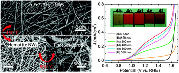
Since hematite nanorod arrays developed by Vayssieres et al. Reference Vayssieres, Beermann, Lindquist and Hagfeldt20 which showed much higher PEC performance than nanoparticulate hematite, Reference Lindgren, Wang, Beermann, Vayssieres, Hagfeldt and Lindquist21 one-dimensional hematite nanostructures have been attracting growing interest for photoelectrodes, mainly because their design reduces the transport distance required for carriers to reach the semiconductor/electrolyte interface. For example, one-dimensional hematite nanowires or nanorods, fabricated via different approaches including hydrothermal growth, Reference de Carvalho, de S. Luz, Lima, Crespilho, Leite and Souza22,Reference Pradhan and Parida23 plasma and air oxidation of Fe precursor films, Reference Chernomordik, Russell, Cvelbar, Jasinski, Kumar, Deutsch and Sunkara24,Reference Grigorescu, Lee, Lee, Albu, Paramasivam, Demetrescu and Schmuki25 radio frequency sputtering, Reference Chang, Wang, Tseng, Cheng, Hourng and Tsai26 were reported to exhibit significant solar water splitting activities, mainly contributed to the channelized electron transport and delayed electron–hole recombination. Li et al. Reference Li, Yu, Meng, Tan, Hamers and Jin27 successfully obtained porous hematite nanowires of high aspect ratio via a simple thermal treatment of α-FeF3·3H2O nanowires in air (Fig. 2) and reported its application as photoanodes for efficient PEC water splitting.
Preparation procedures and photocurrent densities of hematite nanowire photoelectrodes. Reprinted with permission from Reference Li, Yu, Meng, Tan, Hamers and JinRef. 27. Copyright 2012 American Chemical Society.

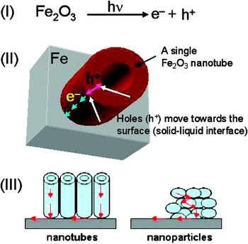
Nanotube is another promising one-dimensional nanostructure with efficient charge carrier transfer ability. Mao et al. Reference Mao, Shin, Kim, Wang, Han and Park28 compared the PEC activities of hematite nanorod and nanotube arrays prepared by the electrochemical deposition method with the help of an anodized aluminum oxide nanotemplate. They found that the hematite nanotubes exhibited much higher PEC activity than the hematite nanorods, including an improved photocurrent density, more negative onset potential, better photon harvesting, and better charge carrier transfer ability. Electrochemical anodization method, frequently used to synthesize TiO2 nanotube arrays, Reference Mor, Prakasam, Varghese, Shankar and Grimes29–Reference Mor, Varghese, Wilke, Sharma, Shankar, Latempa, Choi and Grimes33 can also be applied for the growth of hematite nanotube arrays. Prakasam et al. Reference Prakasam, Varghese, Paulose, Mor and Grimes34 presented for the first time the fabrication of self-aligned nanotubular hematite synthesized via potentiostatic anodization for PEC water splitting. It was believed that the pore walls provided a minimal distance for the photogenerated holes to reach the solution, although electron transport to the underlying iron foil suffered from recombination losses due to increased barrier layer thickness and nonideal material crystallization. Later, modified anodization procedures were developed to synthesize nanotube-based hematite for more efficient PEC water splitting. Mohapatra et al. Reference Mohapatra, John, Banerjee and Misra35 successfully synthesized ultrathin and self-standing hematite nanotubes of 3.7 μm long, 50–60 nm in diameter, and 5–7 nm thick, by sonoelectrochemical anodization method. These hematite nanotubes displayed better PEC activity than nanoporous and nanoparticulate hematite architectures because the charge transport properties of the nanotubes were observed to be 40–50 times higher than those of the nanoparticles (Fig. 3). Zhang et al. Reference Zhang, Hossain and Takahashi36 found that hematite nanotube arrays electrodes prepared using a two-step anodization method also showed much better PEC performance, versus nanoporous and nanoparticulate hematite electrodes, due to the efficient charge separation. Jun et al. Reference Jun, Im, Kim, Im, Jang, Kim, Kim, Kang, Hong and Lee37 fabricated highly ordered honeycomb-like hematite films by double-step anodic oxidation of Fe foil. Compared to nanotubes fabricated by the conventional single-step anodic oxidation process, this highly ordered one-dimensional nanostructure showed much enhanced PEC performances, due to the larger semiconductor–electrolyte contact area and better charge transport with higher orderings of the one-dimensional porous structure. Hematite photoanode of the two-layered oxide structure with a top layer of nanodendrite morphology and a bottom layer of nanoporous morphology was fabricated by Rangaraju et al. Reference Rangaraju, Panday, Raja and Misra38 using a two-step anodization procedure, and showed better photoactivity than the single layer nanotubular hematite. The enhanced photoactivity could be attributed to a combination of the better photocatalytic properties of the nanodendritic iron oxide and better electron transportation behavior of vertically oriented nanochannels.
Schematics of charge carrier transfer in hematite nanotube photoanodes fabricated by the sonoelectrochemical anodization method. Reprinted with permission from Reference Mohapatra, John, Banerjee and MisraRef. 35. Copyright 2009 American Chemical Society.

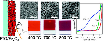
Nanoporous thin films have been considered as good candidates for PEC water splitting, due to their nanoscaled porous structure interfacial charge transfer. Reference Chen, Shen, Guo and Mao2 Sivula et al. Reference Sivula, Zboril, Formal, Robert, Weidenkaff, Tucek, Frydrych and Grätzel39 reported for the first time that relatively high water-splitting photocurrents could be obtained with mesoporous hematite photoanodes prepared by a solution-based colloidal method, shown in Fig. 4. By encapsulation with a SiO2 confinement scaffold before high temperature treatment, the feature size and porous electrode functionality due to dopant activation can be independently controlled. Reference Brillet, Grätzel and Sivula40 This allowed a significant increase in water oxidation photocurrent for this solution-processed hematite photoanode. Gonçalves et al. Reference Gonçalves, Lima and Leite41 demonstrated an alternative way to produce mesoporous hematite photoanodes with high performance using a colloidal dispersion of magnetite nanocrystals as the precursor. It was revealed that a favorable surface rather than an improvement in bulk properties, associated with the textured columnar microstructure, resulted in a photoanode with a low overpotential voltage and a high photocurrent. Transparent mesoporous hematite films were fabricated by Hamd et al. Reference Hamd, Cobo, Fize, Baldinozzi, Schwartz, Reymermier, Pereira, Fontecave, Artero, Robert and Sanchez42 via template-directed sol–gel chemistry coupled with the dip-coating approach. These new materials created a very large interfacial area in contact with the electrolyte allowing for efficient water splitting. Annealing condition was then reported to have great effects on the nanoporous morphology and hence PEC properties of hematite films. Wang et al. Reference Wang, Lee and Schmuki43 found that high temperature Ar annealing could preserve the beneficial small feature size in porous hematite photoelectrodes during annealing, toward achieving a highly photoactive hematite water splitting electrode. Soon after, Rahman and Joo Reference Rahman and Joo44 reported that the surface morphology of the hematite film was altered from a packed worm-like surface to highly porous nanostructures with an increase in the substrate temperature. Similarly, the high PEC performance achieved on the highly porous nanostructures was also due to the small-sized particles in the film near the hematite/electrolyte interface, which facilitated the charge collection and transport relative to charge carrier recombination.
Morphologies and photocurrent densities of mesoporous hematite photoanodes prepared by a solution-based colloidal method. Reprinted with permission from Reference Sivula, Zboril, Formal, Robert, Weidenkaff, Tucek, Frydrych and GrätzelRef. 39. Copyright 2010 American Chemical Society.

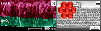
Other specific three-dimensional hematite nanostructures were also designed for promoted charge carrier collection and hence efficient PEC water splitting. For example, by controlling the temperature for thermal oxidation of Fe foils, the hematite morphology could be tuned to a desirable aspect ratio, i.e., nanorod, nanocoral, and nanoleaf structures. Reference Vincent, Gross, Dotan and Rothschild45 The most oxygen-deprived sample, with nanocoral morphology, displayed the best PEC performance possibly because the oxygen vacancies aided the conductivity, which outweighed the negative impact of trapping the holes. Surface morphology was also proved to be the dominant factor in PEC properties of hematite thin films prepared by the electrodeposition technique. Reference Tamboli, Rahman and Joo46 The elongated dumbbell-shaped surface morphology was the optimum morphology of hematite for PEC application than nanosheets or granular morphology. Using pulse reverse electrodeposition method, hematite photoanode with unique nanopetal morphology on fluorine-doped tin oxide (FTO) substrate was fabricated by Shinde et al. Reference Shinde, Go and Lee47 which showed 180% increased photocurrent density relative to the hematite prepared by the normal electrodeposition method. This could be ascribed to the novel nanopetal morphology providing easier percolation pathways for efficient separation and transport of charge carriers. Patil et al. Reference Patil, Shinde, Kim, Lee, Mane and Han48 reported a coordination chemistry approach for shape-controlled synthesis of hematite nanostructures with three distinct morphologies, viz. nanoparticles, nanoparticle chains, and nanorods. The electrode composed of nanoparticle chains was found to afford the lowest charge transfer resistance and thereby the highest photoconversion yield. Zheng et al. Reference Zheng, Kang, Song, Son, Suh, Kim and Kang49 synthesized dendritic hematite array films by annealing Fe dendritic wire array film in air. However, only a low photocurrent was obtained because the dendritic hematite wire was too long to achieve effective light absorption and extract the photogenerated electrons. Fortunately, by atmospheric pressure chemical vapor deposition (APCVD), Kay et al. Reference Kay, Cesar and Grätzel50 successfully obtained a highly developed dendritic nanostructure of 500-nm thickness having a feature size of only 10–20 nm at the surface [Fig. 5(a)]. And an unprecedented high PEC water splitting efficiency was obtained, which could be attributed to the dendritic nanostructure minimizing the distance photogenerated holes have to diffuse to reach the hematite/electrolyte interface while still allowing efficient light absorption. Very recently, Riha et al. Reference Riha, Vermeer, Pellin, Hupp and Martinson51 used the high specific surface area transparent and conducting inverse opal frameworks as scaffolds for fabrication of equally high area hematite structures for PEC water oxidation [Fig. 5(b)]. The frameworks offered high transparency to visible light and robust conductivity under harsh annealing and oxidizing conditions. Furthermore, they also made possible the spatially distributed collection of photocurrent from ultrathin coatings of hematite layers, enabling the formation of photoanodes featuring both large optical extinction and a hematite layer thickness nearly commensurate with the hole-collection distance. The distributed-current-collection approach increased the efficiency of water oxidation with hematite by about a factor of 3 compared with an optimized flat electrode.
Morphologies of hematite (a) dendritic nanostructure. Reprinted with permission from Reference Kay, Cesar and GrätzelRef. 50. Copyright 2006 American Chemical Society. (b) Inverse opal frameworks. Reprinted with permission from Reference Riha, Vermeer, Pellin, Hupp and MartinsonRef. 51. Copyright 2013 American Chemical Society.

III. METAL ION DOPING PROMOTING CHARGE TRANSPORT
Efficient transport of majority charge carriers in hematite is essential for its application for high efficiency PEC water splitting. However, the very low electrical conductivity of hematite (∼10−14/Ωcm), Reference Morin11 attributed to polaron hopping conduction through a Fe3+/Fe2+ valence alternation on spatially localized 3d orbitals, Reference Launay and Horowitz52 greatly limits the photocurrent in hematite. To improve the PEC performance of hematite, plentiful electronic dopants have been frequently introduced into hematite to attain high carrier conductivities, acting as electron donors or electron acceptors.
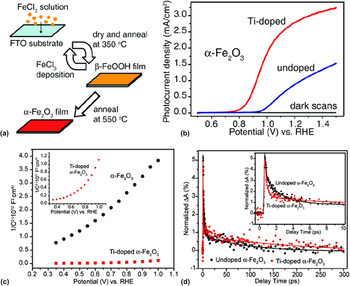
Ti4+, as one of the most studied and effective electron donor dopants, has been successfully introduced into hematite via different approaches, including hydrothermal method, Reference Cao, Luo, Li, Feng, Li and Zou53,Reference Deng, Zhong, Pu, Zhang, Li, Sun and Lee54 sol–gel method, Reference Lian, Yang, Liu, Xu, Jiang, Chen and Wang55 spray-pyrolysis deposition, Reference Kumari, Singh, Sonal, Deva, Shrivastav, Dass and Satsangi56 pulse laser deposition, Reference Kronawitter, Mao and Antoun57 atomic layer deposition (ALD), Reference Zandi, Klahr and Hamann58 APCVD, Reference Zhang, Shwarsctein, Hu, Lefton, Sharma, Formand and McFarland59 etc. For the example shown in Fig. 6, Wang et al. Reference Wang, Ling, Wheeler, George, Horsley, Heske, Zhang and Li60 reported that Ti-doped hematite prepared by a facile deposition-annealing method showed greatly enhanced photocurrent at a relatively low bias (1.83 mA/cm2 at 1.02 V versus RHE) due to the improved donor density and reduced electron–hole recombination at the time scale beyond a few picoseconds. Deng et al. Reference Deng, Zhong, Pu, Zhang, Li, Sun and Lee54 prepared Ti-doped hematite nanostructures with an urchin-like morphology by a hydrothermal method, which performed a photocurrent at 1.23 V versus RHE (1.91 mA/cm2) over 2 times higher than undoped nanostructures. Through electrodeposition or spray method, Zr was successfully incorporated into hematite by Kumar et al., Reference Kumar, Sharma, Shrivastav, Dass and Satsangi61,Reference Kumar, Sharma, Joshi, Shrivastav, Dass and Satsangi62 which gave rise to much higher donor density and better PEC water splitting activity compared to the undoped hematite films. Electrodeposition method was also applied to doping some other metal ions (e.g., Al, Reference Shwarsctein, Huda, Walsh, Yan, Stucky, Hu, Al-Jassim and McFarland63 Pt, Reference Hu, Shwarsctein, Forman, Hazen, Park and McFarland64 Mo, Reference Shwarsctein, Hu, Forman, Stucky and McFarland65 and Cr Reference Shwarsctein, Hu, Forman, Stucky and McFarland65 ) into hematite films as photoelectrodes with enhanced water splitting performances, mainly attributed to the improvement in the charge transport properties within the hematite films. Si-doped hematite prepared by different methods has been reported to show higher photocurrent density than that of undoped hematite. Reference Kay, Cesar and Grätzel50,Reference Yarahmadi, Wijayantha, Tahir and Vaidhyanathan66–Reference Chemelewski, Hahn and Mullins69 It was found that Si dopants could be incorporated into hematite lattice to increase the conductivity, Reference Yarahmadi, Wijayantha, Tahir and Vaidhyanathan66,Reference Lukowski and Jin67 as well as induce the formation of the (110) orientation in the films, which is the favorable orientation with regard to electronic conduction. Reference Kay, Cesar and Grätzel50,Reference Souza, Lopes, Nascente and Leite68 Chemelewski et al. Reference Chemelewski, Hahn and Mullins69 synthesized Si-doped hemitate by coevaporation of pure Si and Fe in an oxygen ambient, which resulted in the segregation of Si at the surface of hematite. Thus, Si acted to passivate the hematite surface and aids charge transfer to the solution, but not improve the bulk conductivity of hematite, for better PEC activity. Sn4+ is another effective dopant for hematite as photoanode for water splitting. Sn dopant in hematite lattice, diffused from the FTO substrate via high temperature annealing Reference Morrish, Rahman, MacElroy and Wolden70,Reference Ling, Wang, Wheeler, Zhang and Li71 or introduced from foreign doping precursors, Reference Ling, Wang, Wheeler, Zhang and Li71,Reference Frydrych, Machala, Tucek, Siskova, Filip, Pechousek, Safarova, Vondracek, Seo, Schneeweiss, Grätzel, Sivula and Zboril72 could serve as an electron donor and enhance electronic conductivity of hematite nanostructures. Reference Meng, Qin, Goddard, Li, Pan, Wen, Qin and Zuo73 Other metal ions, such as W6+, Reference Shen, Kronawitter, Jiang, Mao and Guo74 Ta5+, Reference Aroutiounian, Arakelyan, Shahnazaryan, Stepanyan, Turner and Khaselev75 Nb5+, Reference Sanchez, Hendewerk, Sieber and Somorjai76,Reference Miyake and Kozuka77 Ge4+, Reference Liu, Liang, Xu, Tian, Shao and Zhang78 and Ni2+, Reference Liu, Yu and Zhang79 were also reported to act as effective electron donor dopants for improved PEC activity of hematite as photoanodes. Recently, Rh3+ was doped into hematite for Fe3+ substitution, which not only improved the electrical transport and suppressed the recombination of electron–hole pairs but also enhanced the optical absorption of hematite in the vis and near-infrared (NIR) regions. Reference Seki, Yamahara and Tabata80 Thus, the PEC efficiency was significantly enhanced in the hematite films with Rh doping, in the visible and NIR regions.
(a) Fabrication of hematite photoanodes, (b) photocurrent densities of the undoped and Ti-doped α-Fe2O3 films, and (c) Mott–Schottky plots of the undoped and Ti-doped α-Fe2O3 films. Capacitances were derived from the electrochemical impedance obtained at each potential with 10 kHz frequency in the dark. Inset: magnified Mott–Schottky plot of the Ti-doped α-Fe2O3 film. (d) Normalized ultrafast transient absorption decay profiles of undoped and Ti-doped α-Fe2O3 films in 0–10 ps (inset) and the 0–300 ps windows. They are fit simultaneously using a nonlinear least-squares fitting algorithm to a triple-exponential decay convolved with a Gaussian, representing the cross correlation of the 440 nm pump and 620-nm probe pulses. The solid lines are fitted curves. Reprinted with permission from Reference Wang, Ling, Wheeler, George, Horsley, Heske, Zhang and LiRef. 60. Copyright 2011 American Chemical Society.

Doping hematite to make it p-type using electron acceptor dopants is also believed to enhance its conductivity. Reference Liao, Toroker and Carter81 In Kahn's group, Reference Ingler, Baltrus and Khan82–Reference Ingler and Khan84 Mg2+, Cu2+, and Zn2+-doped hematite films were successfully prepared using a spray pyrolytic deposition method. All these doped hematite films exhibited p-type behavior and showed considerable photocathodic currents for water splitting. It was supposed that the higher acceptor densities of these doped p-type hematite films might be responsible for the significantly higher photocurrent densities because they helped to reduce the resistivity of hematite.
Hematite codoped with two different metal cations was investigated to improve its PEC performance. Sartoretti et al. Reference Sartoretti, Alexander, Solarska, Rutkowska and Augustynski85 reported that hematite codoped with metal cations such as Al3+/Ti4+ and Zn2+/Ti4+ affected the hole diffusion length, leading to a negative shift of the photocurrent onset potential. Jang et al. Reference Jang, Lee, Ye, Fan and Bard86 used scanning electrochemical microscopy in the PEC mode to search for more efficient dopants for hematite photoelectrodes and found hematite simultaneously doped with Sn4+ and Be2+ showing the highest photocurrent as well as a good photosensitivity for water splitting. Recently, Tang et al. Reference Tang, Yin, Matin, Wang, Deutsch, Al-Jassim, Turner and Yan87 used a combination of density functional theory calculation and material synthesis and characterization to examine the properties of charge-compensated Ti and Mg coalloyed hematite thin films for enhanced PEC water splitting performances. They suggested that the charge-compensated donor–acceptor coalloying could lead to reduced electron effective mass and therefore increased electron mobility, optimized electrical conductivity, reduced density of charged defects, and therefore reduced carrier recombination as compared to the noncompensated alloying.
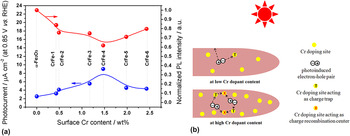
In most doping cases discussed above, the dopants are incorporated into hematite during the growth process, which is of less control over the doping level and would also unintentionally alter the proposed nanostructure with favorable characteristics. Recently, postgrowth doping emerged as a simple and complementary doping strategy, which did not depend on the methods of hematite synthesis and may be applied to any hematite nanostructures for further improved PEC performances. Using these postgrowth doping methods, metal ions were generally incorporated into the surface of nanostructured hematite photoelectrodes. Spray et al. Reference Spray, McDonald and Choi88 uniformly covered a nanoparticulate hematite electrodes with a solution containing metal ions to form a coating layer of Fe2O3–M x O y solid solutions (M = Al and Sn) on hematite nanoparticles upon heating in air. The main effect of Al3+ and Sn4+ ions forming the surface coating layers reduced the surface states or back reactions caused by electrons leaking at the hematite/electrolyte interface, resulting in significantly enhanced photocurrent compared with the untreated samples. Shen et al. Reference Shen, Kronawitter, Jiang, Mao and Guo74,Reference Shen, Jiang, Guo, Kronawitter, Mao and Guo89 successfully tuned the surface composition of hematite nanorod arrays modified by doping of Cr3+ or W6+ using a general process involving a combination of aqueous chemical growth and spin coating. They investigated the dependency relationship between photoluminescence property and photocurrent, which indicated that PEC performance enhancement was mainly due to the reduced charge carrier recombination in the surface-tuned hematite nanorods, as shown in Fig. 7 (taking Cr3+ doping as an example). Later Xi et al. Reference Xi, Chi, Mak, Tran, Barber, Loo and Wong90 described the similar surface treatment of hematite from FeOOH nanorod arrays using Sn4+ ions, which resulted in great photocurrent improvement, mainly due to the reduced electron–hole recombination at the hematite–electrolyte interface through the formation of Fe x Sn1−x O4 layer at the hematite nanorod surface. By electrochemically treating hematite nanotube arrays in Ni2+ aqueous solution, a highly active photoanode consisting of a thin Ni x Fe2−x O3 overlayer on the surface of hematite nanotube was constructed by Cheng et al. Reference Cheng, He, Sun, Peng, Yao, Liu, Jiang, Hu, Xie, He and Wei91 The Ni x Fe2−x O3 overlayer was supposed to promote the charge migration of photogenerated carriers to the surface, accelerating surface oxygen evolution and avoiding low-energy photoexcited hole recombination at the semiconductor–liquid junction. Franking et al. Reference Franking, Li, Lukowski, Meng, Tan, Hamers and Jin92 reported a facile method for postgrowth doping of hematite nanowires via a brief exposure to Ti or Zr dopant precursor solutions and subsequent annealing in air. It was found that the Ti-treatment increased the donor concentration of hematite by about 10-fold and facilitated majority carrier transport and collection, which may account for the performance enhancement.
(a) Photocurrent density and photoluminescence intensity as a function of Cr dopant content for Cr-doped hematite nanorod films. (b) Proposed schemes for photoinduced charge transfer in the Cr-doped hematite nanorod films with different Cr dopant contents. Reprinted with permission from Reference Shen, Jiang, Guo, Kronawitter, Mao and GuoRef. 89. Copyright 2012 Elsevier.

IV. HETEROJUNCTION ENABLING CHARGE SEPARATION
Another crucial issue for hematite to improve the PEC performance is to facilitate the charge separation and effectively conduct photogenerated electrons and holes out of the bulk hematite to back contact and hematite/electrolyte interface for water reduction and oxidation reaction, respectively. Reference Mayer, Lin, Yuan and Wang93 This issue could be addressed in principle by coupling hematite with the second component to form heterojunction at nanoscale. In general, this second component could be the semiconductor to engineer band structures or the charge transporter to conduct photogenerated carriers.
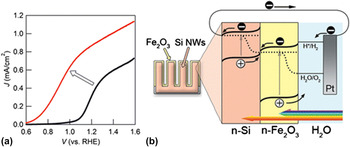
Coupling hematite to another semiconductor with appropriate band structure has been considered to be effective for improving the photogenerated charge separation by means of intercomponent charge transfer. For example, Luo et al. Reference Luo, Yu, Wang, Li, Ye and Zou94 found that the PEC performance of a WO3/α-Fe2O3 nanoelectrode was much higher than that of WO3 or α-Fe2O3 alone, and effective separation of electrons and holes in WO3/α-Fe2O3 was attributed to the photocurrent enhancement. Kronawitter et al. Reference Kronawitter, Vayssieres, Shen, Guo, Wheeler, Zhang, Antoun and Mao95 designed a α-Fe2O3/WO3 core/shell heterostructure and observed by ultrafast transient absorption spectroscopy that the presence of unexpected minority carrier (hole) transfer dynamics via the quantum mechanical tunneling process within the core/shell structure contributed to the PEC performance enhancement. Dhanasekaran et al. Reference Dhanasekaran, Salunke and Gupta96 reported that the photoactivity of γ′-Fe4N/α-Fe2O3 nanocomposites prepared by mechanical mixing of the component materials was many times higher than that of γ′-Fe4N. The selective transfer and entrapment of photoexcited hole carriers due to the favorable valence band potentials of the component photosystems was believed to enable better utilization of electrons, leading thereby to higher photocatalytic activity of water splitting. Fe2O3:Ti/ZnFe2O4 Reference Miao, Ji, Xu, Liu, Zhang and Ye97 and Fe2O3:Co/MgFe2O4 Reference Hou, Zuo, Dagg and Feng98 heterojunction photoelectrodes were also successfully developed to have much higher photocurrents than the single component, mainly due to the excellent charge transfer and enhanced charge separation. Recently, Mayer et al. Reference Mayer, Du and Wang99 showed that when high-quality hematite was deposited on Si nanowires in a conformal fashion, the formed Si/Fe2O3 heterojunction device produced considerably enhanced photocurrent and photovoltage, as compared to standard device of planar hematite. The PEC improvement from the dual-absorber-based “Z scheme” heterojunction (Fig. 8) was evidenced to benefit from a combination of improved light absorption, better charge separation, and overall higher solid/liquid junction area.
(a) J–V plots under simulated solar illumination (AM 1.5, 100 mW/cm2) in 1.0-M NaOH aqueous electrolyte (scan rate 10 mV/s) for the Fe2O3/Si NW system (red) and Fe2O3 on planar FTO (black). (b) Energy band schematics (quasi-static equilibrium under solar illumination) of the hematite/Si NW dual-absorber system. Reprinted with permission from Reference Mayer, Du and WangRef. 99. Copyright 2012 American Chemical Society.

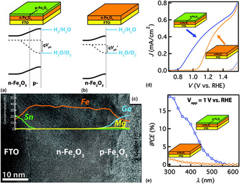
It has been expected in the scheme of PEC water splitting that the p–n junction could facilitate the charge separation and retard the electron–hole recombination. Moreover, the additional photovoltage produced in the p–n junction with rationally engineered band structure goes toward reducing the external applied bias needed to drive water splitting. Reference Mayer, Lin, Yuan and Wang93 Two successful examples have permitted hematite to engineer the p–n junction to the specific application of efficient PEC water splitting. Li et al. Reference Li, Meng, Suri, Ding, Huang and Wu100 fabricated a p–n junction photoanode by depositing p-type NiO nanoparticles on the n-type hematite thin film. In this p-NiO/n-Fe2O3 heterojunction, p-NiO not only facilitated the extraction of accumulated holes from hematite via the p–n junction but also lowered the barrier for oxygen evolution reaction. Lin et al. Reference Lin, Xu, Mayer, Simpson, McMahon, Zhou and Wang101 used ALD to deposit a thin p-type Mg-doped hematite layer over undoped hematite to form a p–n homojunction device with a built-in field created, which could drive charge separation and produce additional photovoltage for PEC water splitting. As a result in Fig. 9, a nominal 200-mV turn-on voltage shift toward the cathodic direction was measured, which was one of the lowest values for hematite synthesized by vapor phase chemistry.
Energy band diagrams and microstructures of hematite with a p-type coating. (a) The introduction of a p-type layer creates a built-in field that does not depend on surface adsorptions, allowing for the measurement of a more substantial photovoltage (Vph). The device structure is schematically illustrated on top. (b) In comparison, although a built-in field can also be achieved on n-type hematite, its depth and magnitude are sensitive to the nature of the electrolyte. (c) Cross-sectional transmission electron micrograph of the n–p junction. Inset: line-scan of energy dispersive spectra of various elements across the film. PEC characterizations of n-type Fe2O3 with and without p-type coating (total thickness: 25 nm). (d) A significant reduction of the turn-on voltage was observed on the sample with p-Fe2O3. Data measured under 1 Sun conditions (100 mW/cm2, AM 1.5 G). Dark currents shown in dashed lines. (e) IPCE characteristics of these samples at 1 V. Reprinted with permission from Reference Lin, Xu, Mayer, Simpson, McMahon, Zhou and WangRef. 101. Copyright 2012 American Chemical Society.

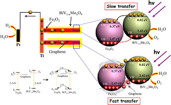
PEC water splitting based on hematite could also be improved by introducing material components of high conductivity to provide a dedicated charge-transport pathway. Some carbon nanomaterials could also act as good charge transporters. By depositing hematite on a highly conductive TiSi2 nanonets, Lin et al. Reference Lin, Zhou, Sheehan and Wang102 reported the highest external quantum efficiency measured on hematite without intentional doping in a water-splitting environment: 46% at λ = 400 nm. The nanonets served a dual role as a structural support and an efficient charge collector, allowing for maximum photon-to-charge conversion. Yu and Kwak Reference Yu and Kwak103 found that the photocatalytic activity of mesoporous hematite nanospheres could be greatly enhanced by embedding carbon quantum dots (CQDs) into the porous framework. This was because the electrons generated on the hematite surface upon visible light illumination could be instantly transferred to the conducting network of the CQDs via a percolation mechanism. The incorporation of functional carbon nanotubes (CNTs) into Ti-doped hematite thin films also resulted in improved PEC properties due to the charge equilibration which interplays between the Ti-doped hematite and CNTs. Reference Liu, Wang, Yu and Zhang104 It was demonstrated that CNTs mediated fast charge transfer and retarded charge recombination rate in the composites. Similarly, the photoactivity of hematite could be greatly enhanced by coupling with graphene, as the coupled graphene was favorable for photogenerated electrons to transfer and then separate in space. Reference He, Jing, Li, Sun and Liu105 The hematite photoanode was then modified with a graphene-CNT composite conducting scaffold for efficient charge transfer from Fe2O3 particles to transparent conducting oxide substrate in PEC water splitting cells. Reference Kim, Jang, Youn, Kim, Kim and Lee106 The Fe2O3-composite photoanode showed a photocurrent increase of 530% compared to the bare Fe2O3 photoanode at 1.23 V versus RHE, whereas the increase was only 200 and 240% for Fe2O3-CNT and Fe2O3–graphene photoanodes, respectively. This remarkable performance enhancement by the composite scaffold was attributed to synergistic effects induced by the formation of a 3D-like architecture from 1D CNT and 2D graphene. Hou et al. Reference Hou, Zuo, Dagg and Feng107 designed a novel heterojunction array of α-Fe2O3/graphene/BiV1−x Mo x O4 core/shell nanorod for PEC water splitting. As schemed in Fig. 10, the improved PEC properties of this graphene-mediated core/shell heterojunction benefited from the improved separation of photogenerated carriers at the α-Fe2O3 nanorod/graphene/BiV1−x Mo x O4 interfaces.
Schematic for the energy band structure of the Fe2O3–NA/RGO/BiV1−x Mo x O4 heterojunction and the proposed mechanism of PEC water splitting. Reprinted with permission from Reference Hou, Zuo, Dagg and FengRef. 107. Copyright 2012 American Chemical Society.

V. SURFACE/INTERFACE MODIFICATION
A. Surface cocatalysts activating water oxidation
The large electrochemical overpotential required by hematite to drive the water oxidation is thought to be caused mainly from the slow kinetics of hole transfer to the solution. Reference Pendlebury, Barroso, Cowan, Sivula, Tang, Grätzel, Kluga and Durrant108 In principle, the kinetics can be improved by modifying hematite surface with specific cocatalysts (e.g., oxygen evolution catalysts, OEC) to facilitate the four-electron process of water oxidation, which generally catalyses hole transfer and results in suppressed surface charge recombination. Reference Shen and Mao6,Reference Yang, Wang, Han and Li109 To this end, some effective OECs have been developed and integrated with hematite electrodes for efficient water splitting by reducing the activation energy for water oxidation.
IrO2, as an effective OEC, has been used to modify various photoanodes for improved PEC activity for water splitting by lowering overpotential. Reference Yokoyama, Hashiguchi, Maeda, Minegishi, Takata, Abe, Kubota and Domen110–Reference Le Paven-Thivet, Ishikawa, Ziani, Le Gendre, Yoshida, Kubota, Tessier and Domen112 Tilley et al. Reference Tilley, Cornuz, Sivula and Grätzel113 reported the significant advance in the performance of hematite by loading IrO2 nanoparticles onto the surface of nanostructured hematite photoanode. IrO2 nanoparticles acting as OEC that has less kinetic barrier for interfacial charge-transfer would lower the overpotential required for water oxidation, for the first time leading to a water splitting photocurrent of over 3 mA/cm2 obtained with hematite at an applied potential of +1.23 V versus RHE under simulated sunlight conditions. IrO x electrodeposited onto hematite using iridium complex was reported to achieve a cathodic shift of 300 mV at 0.2 mA/cm2 photocurrent density. Reference Badia-Bou, Mas-Marza, Rodenas, Barea, Fabregat-Santiago, Gimenez, Peris and Bisquert114 The catalytic mechanism of the IrO x layer could be explained on the basis of a highly capacitive layer, which enhanced charge separation and stored photogenerated holes at Fe2O3, subsequently oxidizing water. Ni compounds have shown to be good catalysts for electrochemical and PEC water oxidation. Reference Sun, Park, Sun, Zhou, Wang, Pang, Shen, Noh, Jing, Jin, Yu and Wang115,Reference Sun, Pang, Shen, Qian, Cheung and Wang116 Wang et al. Reference Wang, Ling, Lu, Zhai, Qian, Tong and Li117 conducted a mechanistic study on the catalytic effect of Ni(OH)2 on hematite nanowires for PEC water oxidation. They observed improved photocurrents for Ni-catalyst-decorated hematite photoanodes, but the photocurrents were not stable. Then, the catalytic mechanism of the Ni(II) catalyst for water oxidation was proposed to be a two-step process: the fast initial oxidation of Ni2+ to Ni3+, and followed by the slow oxidation of Ni3+ to Ni4+. Ni4+ was believed to be the active catalytic species for water oxidation, but its slow formation limited the catalytic effect of the Ni(II) catalyst. NiFe binary oxides were developed by Alan et al. Reference Alan, Hu, Stucky and McFarland118 to act as effective OEC for oxygen evolution reaction on hematite photoanodes. They found that the NiFe oxides electrodeposited from the Ni2+/Fe3+ precursors significantly increased the photocurrent by as much as five times from the IPCE at zero bias as compared to the control sample.
Co compounds have been extensively used as electrocatalysts for water oxidation applications when coated on surface of anodes. Reference Elizarova, Zhidomirov and Parmon119,Reference Artero, Chavarot-Kerlidou and Fontecave120 For example, a catalytic Co2+ monolayer on the hematite surface could result in an 80-mV cathodic shift of photocurrent onset potential, Reference Kay, Cesar and Grätzel50 while Co(OH)2 and CoO x did not show any electrocatalytic effect but rather reduced the photocurrent density. Reference Kay, Cesar and Grätzel50,Reference Majumder and Khan121 Yet cubic Co3O4 nanoparticles could be more active when nanosized to be <5 nm. Reference Jiao and Frei122,Reference Jiao and Frei123 Xi et al. Reference Xi, Tran, Chiam, Bassi, Mak, Mulmudi, Batabyal, Barber, Loo and Wong124 successfully performed incorporation of Co3O4 nanoparticles as OECs into hematite nanorod arrays during hydrothermal growth, which resulted in increased photocurrent and cathodically shifted onset potential of ∼40 mV for PEC water splitting. Riha et al. Reference Riha, Klahr, Tyo, Seifert, Vajda, Pellin, Hamann and Martinson125 coated hematite photoanodes with an ultrathin cobalt oxide [Co(OH)2/Co3O4] layer by ALD and significantly enhanced the PEC water oxidation performance. A 100–200 mV cathodic shift in the photocurrent onset potential was correlated with an order of magnitude reduction in resistance to charge transfer at the Fe2O3/H2O interface.
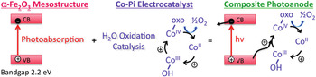
Since the successful demonstration of OECs formed in situ in water containing phosphate and Co2+, Reference Kanan and Nocera126 cobalt(II)–phosphate complexes (Co–Pi) have been coupled to various photoanodes and then work effectively as OECs for PEC water oxidation. Reference Shen and Mao6 Modification of hematite photoanodes by electrodeposition of Co–Pi as OECs was first demonstrated by Zhong et al., Reference Zhong, Sun, Inumaru and Gamelin127 which reduced the bias voltage required for solar PEC water oxidation by >350 mV. This is because the Co–Pi OECs could trap photogenerated holes, which excelled at water oxidation, as schemed in Fig. 11. Reference Zhong and Gamelin128 They also observed that the thickness of electrodeposited Co–Pi layer played an important role in photoanode performance, as thick layers reduced the ability of productive water oxidation to compete with nonproductive surface electron–hole recombination. Reference Zhong and Gamelin128 To overcome the kinetic bottleneck introduced by thick Co–Pi catalyst layer, more uniform distribution of the Co–Pi layer onto the surface of hematite photoanodes was achieved by the photo-assisted electrodeposition method. Reference Zhong, Cornuz, Sivula, Grätzel and Gamelin129 This more sparse Co–Pi layer yielded superior catalytic activity for PEC water oxidation than those prepared by electrodeposition and wet impregnation methods. The effect of the thickness of the Co–Pi layer prepared by photo-assisted electrodeposition was further investigated by Klahr et al. Reference Klahr, Gimenez, Santiago, Bisquert and Hamann130 Unlike the kinetic bottleneck happed to the electrodeposited Co–Pi catalyst layer, thicker photo-assisted electrodeposited Co–Pi layers produced increased water oxidation efficiencies, due to a combination of superior charge separation and increased surface area of the porous catalytic film. Acting as an efficient OEC for PEC water splitting, the Co–Pi catalyst can efficiently collect and store photogenerated holes from the hematite electrode. This charge separation reduces surface state recombination which results in increased water oxidation efficiency. Barroso et al. Reference Barroso, Cowan, Pendlebury, Grätzel, Klug and Durrant131 used transient absorption spectroscopy to probe the dynamics of photogenerated charge carriers in α-Fe2O3/CoO x or Co–Pi nanocomposite photoelectrodes for water splitting. They found that the addition of cobalt-based electrocatalysts increased the lifetime of photogenerated holes in the photoelectrode by more than 3 orders of magnitude without the application of electrical bias. Thus, the enhanced PEC activity of the composite electrode for water photooxidation, at least in part, was proposed from reduced recombination losses because of the formation of a Schottky-type heterojunction. Hong et al. Reference Hong, Liu, Al-Bukhari, Lee, Yung, Chi and Hor132 found that nickel(II)–borate complexes (Ni–Bi) as a novel OEC could cathodically shift the onset potential of photocurrent, resulting in a 9.5-fold enhancement in the photocurrent density observed with the Ni–Bi/Fe2O3 photoanode at 0.86 V versus RHE compared to the parent hematite photoanode. Unlike the Co–Pi OEC improving overall photocatalytic activity over the entire range of potentials, the Ni–Bi OEC modified hematite electrode showed improvement of photocurrent density near the flat potential of hematite with the gradual reduction of photocurrent density in a higher overpotential regime due to the kinetic limitation.
Mechanism of Co–Pi as water oxidation catalyst on the surface of hematite photoanodes. Reprinted with permission from Reference Zhong and GamelinRef. 128. Copyright 2010 American Chemical Society.

To conquer the major barrier of the surface defect and the grain boundary, which hinders the charge transfer between the semiconductor and the inorganic catalyst, very recently, Chen et al. Reference Chen, Ren, Liu, Zhuang and Lu133 developed a new type of photoanode for water splitting, featuring the combination of α-Fe2O3 and molecular Ru catalysts. The semiconductor/molecule interface was not only efficient for the light-induced charge separation but also highly catalytic toward the water oxidation reaction.
B. Surface passivation retarding surface charge recombination
It has been clearly revealed for hematite photoanodes that the hole-transfer step leading to water oxidation takes place predominantly from surface trapped holes and not directly from valence band holes. Reference Klahr, Gimenez, Santiago, Hamann and Bisquert134 The accumulation of holes in surface states at the semiconductor/electrolyte interface is responsible for water oxidation, and thus the charging of this surface state under illumination is related to the shift of the photocurrent onset. In some cases as discussed above, surface modification with some catalytic materials (i.e., OEC) has been shown to reduce the overpotential for water photooxidation and improve the PEC performance for water splitting. In other cases, surface treatment has been suggested to passivate surface states, reducing the kinetics of surface recombination reactions.
A 13-group oxide (Al2O3, Ga2O3, or In2O3) thin overlayer has been demonstrated to effectively passivate surface states to the cathodic shift of the photocurrent onset potential for solar water oxidation with photoanodes. Reference Le Formal, Tétreault, Cornuz, Moehl, Grätzel and Sivula135–Reference Leroy, Maegli, Sivula, Hisatomi, Xanthopoulos, Otal, Yoon, Weidenkaff, Sanjines and Grätzel137 Le Formal et al. Reference Le Formal, Tétreault, Cornuz, Moehl, Grätzel and Sivula135 found that an ultrathin coating of the Al2O3 overlayer by ALD reduced the overpotential required by hematite photoanodes to drive water oxidation by ∼100 mV and increased the photocurrent by a factor of 3.5 at +1.0 V versus RHE under standard illumination conditions. The role of the Al2O3 overlayer is assumed to passivate surface states, eliminating charge recombination through these same surface states that are assumed to cause Fermi level pinning, which can also be understood as a layer reducing the attraction of electrons toward the surface. Reference Le Formal, Sivula and Grätzel138 A facile chemical bath deposition process, instead of ALD, was used by Hisatomi et al. Reference Hisatomi, Le Formal, Cornuz, Brillet, Tétreault, Sivula and Grätzel136 for surface treatment of hematite photoanodes with Al2O3, Ga2O3, and In2O3 overlayers. These 13-group oxide overlayers with the corundum structure were proposed to release lattice strain and decrease the density of surface states of hematite photoanodes. In particular, a Ga2O3 overlayer resulted in a cathodic shift of the onset potential for PEC water oxidation by up to 200 mV. Transient absorption studies under applied bias showed that the cathodic shift of the photocurrent onset observed after surface treatment of Ga2O3 overlayer was accompanied by a similar cathodic shift of the appearance of long-lived hematite photoholes due to a retardation of electron/hole recombination. Reference Barroso, Mesa, Pendlebury, Cowan, Hisatomi, Sivula, Grätzel, Klug and Durrant139 The same group also treated the surface of hematite photoanodes with two overlayers: a cobalt oxo/hydroxo-based (CoO x ) overlayer, reported previously to function as an efficient OEC, and an Al2O3 overlayer, reported to passivate hematite surface states, and investigated their synergetic effects (Fig. 12). Reference Le Formal, Sivula and Grätzel138 They found that the synergetic effect of the Al2O3 and CoO x layers was realizable and occurred with increasing the distance between the electron, in the conduction band and repulsed by the Al2O3 layer, and the hole located in the CoO x layer. A similar synergetic effect was also available by surface adsorption of Co2+ on Ga2O3-modified photoanodes, which produced an additional cathodic shift of the photocurrent onset, confirming the cumulative enhancement of PEC performance caused by the two modifications. Reference Barroso, Mesa, Pendlebury, Cowan, Hisatomi, Sivula, Grätzel, Klug and Durrant139 Xi et al. reported that a very thin ZnO overlayer deposited on top of a thin film of hematite could increase the photocurrent and reduce the onset potential for generating oxygen from water, compared with nontreated hematite. It was proposed that the ZnO overlayer changed the flat band potential of hematite and passivated the surface defects. Reference Xi, Bassi, Chiam, Mak, Tran, Barber, Loo and Wong140
Schematic representation of the effect of bias potential (a and b) and overlayers (c and d) on the band configuration of the photoanode and the relative rates of electron–hole recombination and interfacial charge transfer in a hematite photoanode for water photoelectrolysis (solid lines: majority events; dotted lines: minority events). Reprinted with permission from Reference Le Formal, Sivula and GrätzelRef. 138. Copyright 2012 American Chemical Society.

A facile strategy was developed by Zhang et al. Reference Zhang, Luo, Zhang, Li, Yu and Zou141 to passivate surface states on the undoped hematite photoanode by scanning the photocurrent–time curves in saturated NaCl aqueous electrolyte. The IPCE of the hematite photoanode was increased by a factor of 2.6 at 365 nm and 1.23 V versus RHE after this pretreatment. This enhancement was ascribed to the surface states passivation, which diminished the recombination centers of the photogenerated carriers. By coevaporation of pure Si and Fe in oxygen ambient, Si would segregate to the surface of the formed porous hematite films, which significantly improved the PEC performance relative to undoped porous films. Reference Chemelewski, Hahn and Mullins69 As concluded from the increased extraction efficiency, Si acted to passivate the hematite surface and aided charge transfer to the solution.
C. Effects of the interfacial layer between the substrate and hematite
The trade-off between optical absorption and collection of charge carriers is well known to limit the PEC efficiency of hematite photoanodes. Due to the poor charge transport properties, the thickness of undoped hematite films has to be restricted to typical thicknesses <50 nm for efficient charge carrier collection. It has been expected that for those thin film photoelectrodes, electronic and/or structural interactions with the underlying substrate would critically affect the PEC efficiency, by modulating recombination processes.
Kay et al. Reference Kay, Cesar and Grätzel50 deposited a thin insulating SiO2 interfacial layer between the FTO substrate and the hematite film, which resulted in a much higher photocurrent. The beneficial effect of a thin insulating layer could be due to an improved energy level alignment at the interface, through which electrons from the hematite film can be tunneled to conductive substrate, as in the case of MIS junctions. Further investigations were conducted by the same group to optimize and rationalize the interfacial layer effect. Reference Le Formal, Grätzel and Sivula142 The surprising effect of the interfacial layer of SiO x formed by pretreating the FTO substrate using tetraethoxysilicate (TEOS) was then reported and resulted in drastic improvements in the photoperformance of 12.5-nm thick films of hematite. The formed monolayer of SiO x acted to change the hematite nucleation and growth mechanism, increase its crystallinity, and reduce the concentration of carrier trapping states of the ultrathin hematite films. Hisatomi et al. Reference Hisatomi, Brillet, Cornuz, Le Formal, Tétreault, Sivula and Grätzel143 demonstrated that ultrathin Ga2O3 interfacial layers could serve as an isomorphic (corundum-type) structural template to improve the crystallinity and uniformity of ultrathin hematite films and cathodically shifted the photocurrent onset of PEC water splitting by 0.2 V. Later, they found that the integration of Nb2O5 and TiO2 interfacial layers could also boost the photoconversion efficiency of ultrathin hematite photoelectrodes. Reference Hisatomi, Dotan, Stefik, Sivula, Rothschild, Grätzel and Mathews144 Particularly, the Nb2O5 layers eliminated the photoinactivity of extremely thin films by rendering hematite films as thin as 9 nm active. The principal function of these interfacial layers was attributed to suppression of electron back injection resulting in charge recombination near the hematite/substrate interface. Moreover, these interfacial layers could push forward the development of host–guest-type nanoarchitecture that would allow the combination of efficient charge separation and strong light absorption using ultrathin hematite films.
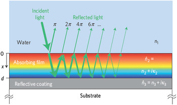
Instead of decoupling, the optical and charge transport path lengths, Dotan et al. Reference Dotan, Kfir, Sharlin, Blank, Gross, Dumchin, Ankonina and Rothschild145 very recently exploited the wave-nature of light propagation in subwavelength structures to tailor the light intensity distribution inside the ultrathin hematite film, amplifying the intensity close to the electrode/electrolyte interface. A water photooxidation current density of 4 mA/cm2 was achieved using ∼26-nm-thick Ti-doped hematite films on back-reflector substrates coated with silver–gold alloy. This is because the escaped back-reflected photons can be harvested by photon retrapping schemes such as using V-shaped cells, thereby further boosting the light-harvesting efficiency (Fig. 13).
Resonant light trapping in quarter-wave films. Schematic illustration of the light propagation in a quarter wave (d = λ/4, for normal incidence) absorbing the film on a back-reflector substrate. The different colors represent the light intensity distribution across the film (red, high; blue, low). Reprinted with permission from Reference Dotan, Kfir, Sharlin, Blank, Gross, Dumchin, Ankonina and RothschildRef. 145. Copyright 2013 Nature Publishing Group.

VI. SUMMARY AND OUTLOOK
Significant advances in the performances of hematite photoelectrodes for solar water splitting, both photocurrent densities and onset potentials, have been achieved over the past few years. A clear blueprint of modification approaches has been preliminarily schemed for substantial further PEC improvements to hematite-based solar water splitting reactions closer to reality. For example, a sizable part of the improvement of photocurrent densities can be attributed to the advances in rationally designed nanostructures and metal ion doping, which allow for efficient charge collection and promoted charge transport. The synergetic effect of nanostructure design and metal ion doping was also realizable for the cumulative enhancement of PEC performances, for instance, effectively occurred with Si- or Ti-doped hematite nanostructures. Forming heterojunctions at nanoscale by coupling the second semiconductor or the charge transporter to hematite has also been evidenced as another effective way to engineer band structures or conduct photogenerated carriers for hematite's performance improvement. Through understanding the kinetic barrier which limits hematite's efficiency, i.e., the accumulation of photogenerated holes at surface states and the slow kinetics of hole transfer to the solution, a variety of surface/interface modifications, including introduction of surface oxygen evolution catalysts or interfacial layers and surface passivation, has been put forward to reduce surface charge recombination and catalyze water oxidation.
Although there have been some encouraging progress, fundamental understanding of hematite's intrinsic limitations is still insufficient. The physical effect of dopants capable of delivering better charge transfer ability is not clear; the mechanistic understanding of catalytic water oxidation needs further exploration. Combined experimental and theoretical studies at the advanced level are required to both better understand the fundamental properties and exploit various technological applications of nanostructured hematite photoelectrodes. Density functional theory calculations greatly help elucidate detailed reaction mechanisms and energetics for hole transport in hematite and water oxidation reaction on the hematite surface. Reference Liao, Keith and Carter146,Reference Liao and Carter147 Ultrafast transient absorption spectroscopy seems powerful to gain insight into the fundamental charge carrier dynamics of undoped or doped hematite nanostructures. Reference Wheeler, Wang, Ling, Li and Zhang16,Reference Huang, Lin, Xiang, Córdoba, McDonald, Hagen, Choi, Brunschwig, Musaev, Hill, Wang and Lian148 Synchrotron-based soft x-ray absorption spectroscopy can be used to probe the fine electronic structures at and near the interface of hematite-based heterojunctions to facilitate future efforts to engineer favorable interfacial compositions and associated electrochemical potential gradients within photoanodes. Reference Kronawitter, Zegkinoglou, Rogero, Guo, Mao, Himpsel and Vayssieres149,Reference Kronawitter, Bakke, Wheeler, Wang, Chang, Antoun, Zhang, Guo, Bent, Mao and Vayssieres150 Surface photoelectrochemistry of the kinetics and mechanisms of the reactions involved deserves with particular emphasis on the effects of slow interfacial charge transfer at hematite (also other semiconductors) electrodes in the case of light-driven oxygen evolution. Reference Peter151–Reference Cummings, Marken, Peter, Wijayantha and Tahir154 Though the state-of-the-art of hematite photoelectrodes is still far from optimal and practical application for solar energy conversion, hematite still possesses many ideal characteristics for solar water splitting. The recent advances presented in the review article give strong anticipation and perspective that continued efforts will bring hematite eventually to be a practical photoelectrode for water oxidation.
ACKNOWLEDGMENTS
The authors gratefully acknowledge the financial support of the National Natural Science Foundation of China (Grant Nos. 51102194 and 51121092), the Doctoral Program of the Ministry of Education (Grant No. 20110201120040), and the National Basic Research Program of China (Grant No. 2009CB220000). One of the authors (S. Shen) was supported by the “Fundamental Research Funds for the Central Universities.”