




1. Introduction
A liquid plug in a container with a small cross-section may or may not occur depending on the container geometry, gravity and surface tension. An understanding of the hydrostatics of liquid plugs in a container is important in a number of applications. Examples include liquid plugs in fuel cells (Herescu & Allen Reference Herescu and Allen2012), liquid filling in a gap in micro-gravity (Chen & Collicott Reference Chen and Collicott2006), and liquid occlusion in microfluidics and micro-electromechanical systems (Gravesen, Branebjerg & Jensen Reference Gravesen, Branebjerg and Jensen1993). Liquid plugs may be harmful to the performance of the equipment. Generally, it is very important to optimally design the containers (mainly including designing the tube geometry and setting the material surface properties) to avoid liquid plugs in them.
To understand the liquid plug phenomenon, it is necessary to find the equilibrium capillary surfaces spanning the containers and to propose criteria for the occlusion of the liquid. Concus & Finn (Reference Concus and Finn1969) and Finn (Reference Finn1986) developed a well-known theory to propose criteria for the existence and non-existence of an occluding capillary surface in a cylinder for cases under weightless conditions or in a gravity field parallel to the axis of the cylinder. Smedley (Reference Smedley1990) applied Finn's (Reference Finn1986) theory to the cases of four different cross-sections (one of them being eccentric annuli) for various wetting angles under weightless conditions. Pour & Thiessen (Reference Pour and Thiessen2019) extended Smedley's (Reference Smedley1990) work to the case of both non-wetting and wetting liquids with a given sufficient volume in an annular geometry between two non-concentric cylinders under weightless conditions. In a geometric parameter space, they found the occluding region where only the occluding configuration occurs, the non-occluding region where only the non-occluding bridging configuration occurs, and a bistable region where either configuration can exist.
De Lazzer et al. (Reference De Lazzer, Langbein, Dreyer and Rath1996) used a numerical method to calculate the capillary pressure in a rotating polygonal cylinder, when a body force is perpendicular to the axis of the cylinder. De Lazzer et al. (Reference De Lazzer, Stange, Dreyer and Rath2003) investigated the shapes of liquids pinned between two parallel plates under the effect of a lateral body force. Manning, Collicott & Finn (Reference Manning, Collicott and Finn2011) extended the known theory (Concus & Finn Reference Concus and Finn1969; Finn Reference Finn1986) to include transverse body forces, leading to an explicit mathematically rigorous occlusion criterion for cylindrical tubes in a transverse body force field, depending on the force magnitude and contact angle. The critical Bond number was used as an important parameter to determine the existence or non-existence of capillary plugs. If the Bond number is less than the critical Bond number, a plug in the tube may occur; otherwise a plug in the tube will not occur. They presented a precise analytic criterion for a liquid plug in a circular cylinder. Manning et al.'s (Reference Manning, Collicott and Finn2011) analytic theory is in good agreement with direct calculations for the surfaces of minimizing energy via Surface Evolver (Brakke Reference Brakke1992) in three-dimensional mode. Based on the Manning et al. (Reference Manning, Collicott and Finn2011) theory, Manning & Collicott (Reference Manning and Collicott2015) presented an exhaustive determination of the critical Bond number for the existence of occluding capillary surfaces in horizontal rectangular channels with uniform contact angles in a downward gravity field. The effects of aspect ratios (defined as the width-to-height ratio) and contact angles on the critical Bond number of the rectangular tube were examined. The critical Bond numbers for liquid plugs in the tubes with different cross-sectional shapes (including circle, oblate and prolate ellipses of different aspect ratios, and triangles) and different contact angles were determined (Rascón, Parry & Aarts Reference Rascón, Parry and Aarts2016).
Researchers have sought to find methods for preventing the existence of liquid plugs. For this purpose, a wedge was found by Concus & Finn (Reference Concus and Finn1969) to be able to avoid liquid plugs in a cylindrical container. When the sum of the contact angle and half of the interior angle of the corner is less than  $90^{\circ }$, a liquid plug will not occur or the surface will not exist. Manning et al. (Reference Manning, Collicott and Finn2011) designed a ‘flattened ice-cream cone’ cylinder in which non-occluding will occur. Square hydrophilic channels are utilized in fuel cells to prevent liquid water plugs in them (Zhang, Yang & Wang Reference Zhang, Yang and Wang2006). Compared to the contact angle
 $\gamma =90^{\circ }$, both
 $\gamma >90^{\circ }$ and
 $\gamma <90^{\circ }$ can decrease the critical Bond number (Manning et al. Reference Manning, Collicott and Finn2011). A sufficiently large aspect ratio can lead to reduction of the critical Bond number of a rectangular tube (Manning & Collicott Reference Manning and Collicott2015). However, in some applications, the cross-section of the liquid partially filling the tube is determined mainly by the performance of the equipment containing the flow tube and may not be changed only due to the liquid plug performance. Furthermore, the reduction of critical Bond number due to
 $\gamma >90^{\circ }$ or
 $\gamma <90^{\circ }$ and the use of rectangular cross-section of very large aspect ratio (Manning & Collicott Reference Manning and Collicott2015) is small, and the value of the critical Bond number is of the same order of magnitude as before. It is necessary to seek alternative methods of making the formation of liquid plugs as difficult as possible.
The above work has been focused on finding the equilibrium capillary surfaces and determining the critical Bond numbers for liquid plugs in tubes, where the contact angles on the walls are uniform. What are the configurations of the equilibrium capillary surfaces in infinitely long tubes with walls of differing contact angles (called non-uniform contact angles here)? How does the non-uniformity of contact angles influence the critical Bond numbers for liquid plugs in the tubes? Is the non-uniformity of contact angles helpful for obtaining much smaller critical Bond numbers or not? These questions have not been studied to date. Here, we answer them by taking rectangular tubes as an example, because a rectangle can serve as a canonical form to extend to other polygonal shapes.
In this paper, a mathematical model that considers the effects of transverse gravity and surface tension is given to calculate equilibrium capillary surfaces in infinitely long rectangular tubes. Manning et al.'s (Reference Manning, Collicott and Finn2011) method is applied to the existence of capillary plugs in rectangular tubes. The effect of different settings of the non-uniform contact angles on the critical Bond number is investigated. Finally, the critical Bond numbers for liquid plugs in the rectangular tubes with the walls of differing contact angles for different aspect ratios are determined.
2. Methods
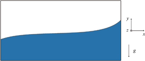
Consider a long horizontal rectangular tube partially filled with a liquid in a downward gravity field, as depicted in figure 1. The length of the tube is assumed infinite;  $w$ and
 $h$ are the width and height of the tube cross-section, respectively; and the aspect ratio is defined as
 $w/h$. The gas and the liquid in the tube are immiscible fluids and both of them have very large fixed volumes. Physically, the static equilibrium of the gas–liquid interface is supported by gravity and the surface tension forces at contact points (contact lines in three dimensions).
Schematic of general cross-section of liquid partially filling a rectangular tube in a downward gravity field. The interior  $\varOmega$ is divided into
 $\varOmega ^*$ and (
 $\varOmega -\varOmega ^*$) by the arc
 $\varGamma$; the perimeter
 $\varSigma$ is divided into
 $\varSigma ^*$ and (
 $\varSigma -\varSigma ^*$);
 $\psi$ is the inclination angle on the arc
 $\varGamma$; and
 $\gamma _1$,
 $\gamma _2$,
 $\gamma _3$ and
 $\gamma _4$ are the contact angles of the four walls, respectively.

2.1. Young–Laplace equation in two dimensions
We assume that the gas–liquid interface is in equilibrium in a horizontal rectangular tube in a downward gravity field (figure 1). By solving the Young–Laplace equation in two dimensions (Bhatnagar & Finn Reference Bhatnagar and Finn2016):
 \begin{equation} \left(\frac{y_x}{\sqrt{1+y_x^2}}\right)_x \equiv (\sin\psi)_x=\lambda+\kappa y, \end{equation}
the height  $y(x)$ of the liquid surface can be determined, yielding the equilibrium condition for the gas–liquid interface. In this equation, the subscript
 $x$ represents the derivative with respect to the coordinate
 $x$ (i.e.
 $(\cdot )_x \equiv \textrm {d}(\cdot )/\textrm{d}\kern0.05em x$),
 $\psi$ is the inclination angle of the curve
 $y(x)$ and
 $\kappa =\rho g/\sigma$ is the capillary constant, with
 $\rho$ the density difference (positive) between liquid and gas,
 $g$ the gravitational acceleration,
 $\sigma$ the surface tension of the interface, and
 $\lambda$ is a constant depending on the eventual volume constraint. The boundary condition remains as
 \begin{equation} \boldsymbol{\nu} \boldsymbol{\cdot} \boldsymbol{T}y = \cos\gamma, \quad \boldsymbol{T}y \equiv \boldsymbol{\nabla}y/\sqrt{1+{ |\boldsymbol{\nabla}y |}^2}, \end{equation}
where  $\boldsymbol {\nu }$ is the unit exterior normal to the rectangle on
 $\varSigma$, and
 $\gamma$ is the contact angle.
We can obtain the solutions of (2.1) by integrating the parametrization form of (2.1). There are two parametrization forms of (2.1). Following Bhatnagar & Finn (Reference Bhatnagar and Finn2016), we have
 \begin{equation} \frac{\textrm{d}\kern0.05em x}{\textrm{d} \psi}=\frac{\cos \psi}{\lambda+\kappa y}, \quad \frac{\textrm{d} y}{\textrm{d} \psi}=\frac{\sin \psi}{\lambda+\kappa y}. \end{equation}
A first integral of the form is (Bhatnagar & Finn Reference Bhatnagar and Finn2016; Zhou & Zhang Reference Zhou and Zhang2017):
 \begin{equation} c=\frac{(\lambda+\kappa y_0)^2}{2 \kappa}+\cos \psi_0. \end{equation}
The solutions according to the range of the integral constant  $c$ are uniquely determined by the prescribed point (
 $x_0, y_0$) on the interface and the inclination angle
 $\psi _0$ of the interface at the prescribed point. Explicitly integrating the terms of (2.3a,b), we obtain
 \begin{gather} x = {x_0} + \int_{{\psi_0}}^{\psi} {\frac{{\cos \tau }}{{ \pm \sqrt{2\kappa (c - \cos \tau )} }}}\,\textrm{d}\tau , \quad \psi \in \left[ {{\psi_0},\frac{{\rm \pi} }{2}} \right], \end{gather}
 \begin{gather} y = - \frac{\lambda}{\kappa} \pm \frac{1}{\kappa}\sqrt{2\kappa(c - \cos\psi)}. \end{gather}
Equation (2.1) also can be parametrized by the arclength  $s$ (Finn Reference Finn1986) as
 \begin{equation} \frac{{\textrm{d}\kern0.05em x}}{{\textrm{d}s}} = \cos \psi ,\quad \frac{{\textrm{d}y}}{{\textrm{d}s}} = \sin \psi ,\quad \frac{{\textrm{d}\psi }}{{\textrm{d}s}} = \frac{{\textrm{d}\kern0.05em x}}{{\textrm{d}s}}\frac{{\textrm{d}\psi }}{{\textrm{d}\kern0.05em x}} = \lambda + \kappa y, \end{equation}
which hold the solution curves (corresponding to  $0<c<1$ in (2.4)–(2.6)) each containing an inflection point. Equations (2.5) and (2.6) are employed in calculation for the family of solution curves with
 $c>1$, and (2.7a–c) are employed in calculation for the family of solution curves with
 $0<c\leq 1$.
2.2. Occlusion criteria
The plug criterion for an infinitely long horizontal rectangular tube partially filled by liquid in a downward gravity field is developed by extending Manning et al.'s (Reference Manning, Collicott and Finn2011) plug criterion for a cylindrical tube. The two inequalities that are necessary for the existence of an occluding interface are
 \begin{equation} {{\varPhi }} [ {{{{\varOmega }}^*}} ] \equiv | {{\varGamma }} | - \int_{{\varSigma ^*}} {\cos \gamma } + \frac{{ | {{{{\varOmega }}^*}} |}} {{ | {{\varOmega }} |}}\int_{\varSigma} {\cos \gamma } + \kappa \int_{{{{\varOmega }}^*}} y > 0, \end{equation}
and
 \begin{equation} {{\varPsi }} [ {{{{\varOmega }}^*}} ] \equiv | {{\varGamma }} | + \int_{{\varSigma ^*}} {\cos \gamma } - \frac{{ | {{{{\varOmega }}^*}} |}} {{ | {{\varOmega }} |}}\int_{\varSigma} {\cos \gamma } - \kappa \int_{{{{\varOmega }}^*}} y > 0. \end{equation}
If one of the above two inequalities is not satisfied for an  $\varOmega ^*$, a plug surface will not exist. We choose the constant
 $\lambda$ as
 \begin{equation} \lambda = \frac{{1}}{{| {{\varOmega }} |}} \int_{\varSigma} {\cos \gamma }= \frac{{(\cos{\gamma _1} + \cos {\gamma _3}) + (w/h)(\cos {\gamma _2} + \cos {\gamma _4})}}{w}, \end{equation}
and the centroid of the rectangle lies on the  $x$-axis. The Bond number (
 $B$) is defined based on the height of the tube cross-section
 $h$ (used as the characteristic length) as
 $B = ({{\rho g}}/{\sigma }){h^2}$. The critical Bond number (
 $B_c$) is used as the parameter to determine the existence or non-existence of capillary plugs. If
 $B < B_c$, a plug in the tube may occur; otherwise, a plug will not occur. Newton's method is used for iterative computations of the above equations.
3. Results and discussion
3.1. Effect of uniform contact angles
For contact angles smaller than  $45^{\circ }$ or larger than
 $135^{\circ }$, the liquid will critically wet the corners of the rectangle regardless of the Bond number (Concus & Finn Reference Concus and Finn1969). The critical Bond numbers of a square tube and a rectangular tube of
 $w/h=2$ for uniform contact angles (
 $\gamma _1=\gamma _2=\gamma _3=\gamma _4$) varying from
 $45^{\circ }$ to
 $135^{\circ }$ with an increment of
 $1^{\circ }$ are shown in figure 2. The results are in excellent agreement with those calculated by Manning & Collicott (Reference Manning and Collicott2015). The curve is symmetric about the vertical line
 $\gamma =90^{\circ }$ (verified in § 3.2) and reaches a maximum at
 $\gamma =90^{\circ }$. In other words, both
 $\gamma >90^{\circ }$ and
 $\gamma <90^{\circ }$ can lead to the reduction of
 $B_c$. The contact angle
 $\gamma$ can be found to produce the same
 $B_c$ value as the contact angle
 $180^{\circ }-\gamma$. Furthermore, different from the smooth curve of the square, the curve for
 $w/h=2$ has two kinks (each corresponding to a topological change in the non-occluded liquid configuration between a single connected region and two separated corner regions) at
 $\gamma =49^{\circ }$ and
 $131^{\circ }$ so that the minimum of
 $B_c$ is smaller than that of the square tube (also see Manning & Collicott Reference Manning and Collicott2015).
Critical Bond numbers of two rectangular tubes versus uniform contact angles.

3.2. Effect of non-uniform contact angles
In reality, the contact angle on one wall of a tube may be different from the contact angles on the other walls. We take a square tube as an example to analyse the effect of the non-uniform contact angles on  $B_c$. Owing to the symmetry of the two sidewalls, the effect of the contact angle of one sidewall
 $\gamma _1$ is equivalent to the effect of the contact angle of the other sidewall
 $\gamma _3$. Figure 3 shows the variations of
 $B_c$ for different contact angles (
 $\gamma _2=\gamma _4=45^{\circ }$,
 $60^{\circ }$,
 $75^{\circ }$,
 $90^{\circ }$,
 $105^{\circ }$,
 $120^{\circ }$ and
 $135^{\circ }$) with the contact angles
 $\gamma _1=\gamma _3$. In figure 3, the curves are still symmetric about the vertical line
 $\gamma _1=\gamma _3=90^{\circ }$ and reach maxima at
 $\gamma _1=\gamma _3=90^{\circ }$. A larger difference in the contact angles
 $\gamma _2=\gamma _4$ from
 $90^{\circ }$ leads to the reduction of
 $B_c$. However, the maximum and minimum of
 $B_c$ do not change any more compared to the case for the uniform contact angles (
 $\gamma _1=\gamma _2=\gamma _3=\gamma _4$).
Critical Bond number of a square tube for different values of contact angles  $\gamma _2=\gamma _4$ versus contact angles
 $\gamma _1=\gamma _3$.

In order to further analyse the effect of the non-uniformity of  $\gamma _2$ and
 $\gamma _4$ effectively, the contact angles studied have the relationship
 $\gamma _4=180^{\circ }-\gamma _2$. In this case, the maximum non-uniformity of the two contact angles is generated when
 $\gamma _2=45^{\circ }$ or
 $135^{\circ }$. It is found from figure 4 that the lower contact angle on the bottom wall with the greater contact angle on the top wall can lead to effective reduction of
 $B_c$, and, in contrast, the reverse can lead to effective increase of
 $B_c$. The minimum is reached for
 $\gamma _2=45^{\circ }$ and
 $\gamma _4=135^{\circ }$ and the maximum of 13.66 is attained for
 $\gamma _2=135^{\circ }$ and
 $\gamma _4=45^{\circ }$.
Critical Bond number of a square tube for different values of contact angles  $\gamma _2$ and
 $\gamma _4=180^{\circ }-\gamma _2$ versus contact angles
 $\gamma _1=\gamma _3$.

We will analyse the effect of the non-uniformity of the two side contact angles  $\gamma _1$ and
 $\gamma _3$ based on the maximum non-uniformity of the bottom and top contact angles. In order to reduce the number of representative cases for comprehensive study in this respect as much as possible, we initially analyse the relationship of
 $B_c$ for the case with contact angles
 $\gamma _1$,
 $\gamma _2$,
 $\gamma _3$ and
 $\gamma _4$ and that for the case with
 $\gamma _1^+=180^{\circ }-\gamma _1$,
 $\gamma _2^+=180^{\circ }-\gamma _4$,
 $\gamma _3^+=180^{\circ }-\gamma _3$ and
 $\gamma _4^+=180^{\circ }-\gamma _2$. The interfaces of the two cases are shown in figure 5. Since (2.8) and (2.9) are equivalent, we compare the values of
 $\varPhi$ for the two cases. For the two cases as shown in figures 5(a) and 5(b) the
 $\varPhi$ values are, respectively,
Interface of rectangular tube (a) with contact angles  $\gamma _1$,
 $\gamma _2$,
 $\gamma _3$ and
 $\gamma _4$ and (b) with
 $\gamma _1^+ = 180^{\circ } - {\gamma _1}$,
 $\gamma _2^+ = 180^{\circ } - {\gamma _4}$,
 $\gamma _3^+ = 180^{\circ } - {\gamma _3}$ and
 $\gamma _4^+ = 180^{\circ } - {\gamma _2}$.

 \begin{align} {\varPhi_a} &= | {{\varGamma _a}} | - (| {\varSigma _{a1}^*} |\cos {\gamma _1} + | {\varSigma _{a2}^*} |\cos {\gamma _2} + | {\varSigma _{a3}^*} |\cos {\gamma _3} + | {\varSigma _{a4}^*} |\cos {\gamma _4} ) \nonumber\\ &\quad + \frac{{| {\varOmega _a^*}|}}{{| \varOmega |}}\int_{\varSigma} {\cos \gamma } + \kappa \int_{{{\varOmega}}_a^*} y, \end{align}
and
 \begin{align} {\varPhi_b} &= | {{\varGamma _b}} | - (| {\varSigma _{b1}^*} |\cos \gamma _1^+ + | {\varSigma _{b2}^*} |\cos \gamma _2^+ + | {\varSigma _{b3}^*} |\cos \gamma _3^+ + | {\varSigma _{b4}^*} |\cos \gamma _4^+ ) \nonumber\\ &\quad + \frac{{| {\varOmega _b^*} |}}{{| \varOmega |}}\int_{\varSigma} {\cos {\gamma ^+}} + \kappa \int_{\varOmega _b^*} y. \end{align}
From (2.5), (2.6) and (2.10), we find that the  $y$ values of the two interfaces are symmetric about the
 $x$-axis. Therefore,
 $\kappa \int _{\varOmega _b^*} y=\kappa \int _{\varOmega _a^*} y$. Moreover, the arclengths, the areas and the perimeters have the relations, respectively:
 $|\varGamma _a|=|\varGamma _b|$,
 $|\varOmega _a^*|=|\varOmega |-|\varOmega _b^*|$ and
 $|\varSigma _a^*|=|\varSigma |-|\varSigma _b^*|$. In this case, (3.2) can be rewritten as
 \begin{align} {\varPhi_b} &= | {{\varGamma _a}} | - \left({\int_{\varSigma} {\cos \gamma } ^+} - |{\varSigma _{a1}^*} |\cos \gamma _1^+ - |{\varSigma _{a2}^*} |\cos \gamma _4^+ - |{\varSigma _{a3}^*} |\cos \gamma _3^+\right.\nonumber\\ &\quad\left. - | {\varSigma _{a4}^*} |\cos \gamma_2^+\vphantom{\int_{\varSigma}}\right) + \frac{{(| \varOmega | - | {\varOmega _a^*} |)}}{{| \varOmega |}}\int_{\varSigma} {\cos {\gamma ^+}} + \kappa \int_{ | {\varOmega _a^*} |} y \nonumber\\ & = | {{\varGamma_a}} | + (| {\varSigma _{a1}^*} |\cos {\gamma _1^+} + |{\varSigma _{a2}^*} |\cos \gamma _4^+ + | {\varSigma _{a3}^*} |\cos {\gamma _3^+} + | {\varSigma _{a4}^*} |\cos \gamma _2^+ ) \nonumber\\ &\quad - \frac{| {\varOmega _a^*}|}{{| \varOmega |}}{\int_{\varSigma} {\cos \gamma^+ } }+ \kappa \int_{ |{\varOmega_a^*} |} y. \end{align}
Based on the relation of the contact angles as shown in figure 5(a) and those in figure 5(b),  $\int _{\varSigma } {\cos \gamma ^+}$ is equal to
 $-\int _{\varSigma } {\cos \gamma }$ from (2.10), and
 $\varPhi _b$ is equal to
 $\varPhi _a$ from (3.1) and (3.3). It is concluded that the value of
 $B_c$ of a rectangular tube with contact angles
 $\gamma _1$,
 $\gamma _2$,
 $\gamma _3$ and
 $\gamma _4$ is equal to that with
 $\gamma _1^+=180^{\circ }-\gamma _1$,
 $\gamma _2^+=180^{\circ }-\gamma _4$,
 $\gamma _3^+=180^{\circ }-\gamma _3$ and
 $\gamma _4^+=180^{\circ }-\gamma _2$. (The uniform contact angles of
 $\gamma _1=\gamma _2=\gamma _3=\gamma _4=\gamma$, and
 $\gamma _1^+=\gamma _2^+=\gamma _3^+=\gamma _4^+=180^{\circ }-\gamma$ are special cases. The
 $B_c$ value for the uniform contact angle
 $\gamma$ is equal to that for the uniform contact angle
 $180^{\circ }-\gamma$.) In this case, the range of
 $\gamma _1$ from
 $45^{\circ }$ to
 $135^{\circ }$ and the range of
 $\gamma _3$ from
 $90^{\circ }$ to
 $135^{\circ }$ are representative for the comprehensive studies on the influence of the non-uniformity of
 $\gamma _1$ and
 $\gamma _3$.
The critical Bond numbers of a square tube versus contact angle  $\gamma _1$ with
 $\gamma _3$ changing among
 $90^{\circ }$,
 $105^{\circ }$,
 $120^{\circ }$ and
 $135^{\circ }$ for the case
 $\gamma _2=45^{\circ }$ and
 $\gamma _4=135^{\circ }$ and the case
 $\gamma _2=135^{\circ }$ and
 $\gamma _4=45^{\circ }$ are shown in figure 6. The curve is no longer symmetric about the vertical line of
 $90^{\circ }$, as it is in figures 2–4. The minimum of
 $B_c=0$ reached at
 $\gamma _1=\gamma _2=45^{\circ }$ and
 $\gamma _3=\gamma _4=135^{\circ }$ (figure 6a) is lower than that shown in figure 4. The maximum 13.66 reached at
 $\gamma _2=135^{\circ }$,
 $\gamma _4=45^{\circ }$ and
 $\gamma _1=\gamma _3=90^{\circ }$ (figure 6b) is equal to that shown in figure 4. This implies that the non-uniformity of the two side contact angles can help to reduce the minimum of
 $B_c$ but never influence the maximum. Furthermore, the minimum of
 $B_c$ attained by optimizing the non-uniform contact angles is far lower than the minima attained by changing the uniform contact angles and by increasing the aspect ratio to a very large value (Manning & Collicott Reference Manning and Collicott2015). Optimization of the non-uniform contact angles can therefore be considered as a more effective method of preventing the existence of liquid plugs.
Critical Bond number of a square tube versus contact angle  $\gamma _1$ with
 $\gamma _3$ changing among
 $90^{\circ }$,
 $105^{\circ }$,
 $120^{\circ }$ and
 $135^{\circ }$ for
 $(a)$
 $\gamma _2=45^{\circ }$ and
 $\gamma _4=135^{\circ }$ and
 $(b)$
 $\gamma _2=135^{\circ }$ and
 $\gamma _4=45^{\circ }$.

3.3. Effect of aspect ratios for non-uniform contact angles
The aspect ratio of the tube with rectangular cross-section has been found to change the minimum of  $B_c$ but not to change the maximum 8.0, for uniform contact angles. Moreover, a very large aspect ratio (= 100) leads to a smaller value of
 $B_c$ for uniform contact angles
 $46^{\circ }$ or
 $134^{\circ }$, but it is still larger than 3.5 (Manning & Collicott Reference Manning and Collicott2015). Here, we intend to examine the effect of the aspect ratio of the rectangular cross-section on the minimum and maximum of
 $B_c$ for a tube with walls of differing contact angles. As demonstrated in previous sections, the variation of contact angles is complex for comprehensively studying the effect of the non-uniformity of contact angles. In this context, the cases of
 $\gamma _1$ changing from
 $45^{\circ }$ to
 $135^{\circ }$ for
 $\gamma _2=45^{\circ }$ and
 $135^{\circ }$,
 $\gamma _3=90^{\circ }, 105^{\circ }, 120^{\circ }$ and
 $135^{\circ }$ and
 $\gamma _4=135^{\circ }$ and
 $45^{\circ }$ are chosen, which include the two cases corresponding, respectively, to the minimum and maximum of
 $B_c$ (figure 7).
Critical Bond number of a rectangular tube ( $w/h=2$) versus contact angle
 $\gamma _1$ with
 $\gamma _3$ changing among
 $90^{\circ }$,
 $105^{\circ }$,
 $120^{\circ }$ and
 $135^{\circ }$ for
 $(a)$
 $\gamma _2=45^{\circ }$ and
 $\gamma _4=135^{\circ }$ and
 $(b)$
 $\gamma _2=135^{\circ }$ and
 $\gamma _4=45^{\circ }$.

We compare the values of  $B_c$ for the chosen cases for a rectangle with
 $w/h=2$ (figure 7) and a square (figure 6). It is found that the aspect ratio does not change the minimum and maximum of
 $B_c$ (table 1). In other words, the aspect ratio of the rectangular cross-section has no effect on the minimum and maximum of
 $B_c$ for a tube with walls of differing contact angles. This conclusion also can be obtained by substituting the contact angles for the minimum and maximum of
 $B_c$ into (2.8) and (2.9). However, for the square, there is only one non-occluded liquid configuration with the gas–liquid interface meeting the two sidewalls (as the type 1 topology) while for the rectangle, besides the type 1 topology, another non-occluded liquid configuration having two contact points in one corner region or having four contact points in two separated corner regions may occur (as the type 2 topology) (figure 8). The transition between the two topologies is accompanied by the kink of the curve of
 $B_c$ for the rectangle. Only one topology leads to no kink of the curve of
 $B_c$ for the square. Figure 9 shows a three-dimensional view of the interface shapes for occluding liquid configurations in the rectangle with
 $w/h=2$ for different cases directly calculated using Brakke's Surface Evolver (Reference Brakke1992).
Critical Bond number as a function of contact angle for a capillary with two rectangular cross-sections: (a–d) square and (e–h) rectangle with  $w/h=2$. Panels (a) and (e) are for uniform contact angles, while panels (b–d) and (f–h) are for non-uniform contact angles. In the latter, the contact angles
 $\gamma _1=\gamma _2$ vary from
 $45^{\circ }$ to
 $135^{\circ }$ and
 $\gamma _3=\gamma _4=45^{\circ }$ (b and f),
 $90^{\circ }$ (c and g) and
 $135^{\circ }$ (d and h). The red circles denote the data at five representative contact angles,
 $\gamma _1=\gamma _2=50^{\circ }, 70^{\circ }, 90^{\circ }, 110^{\circ }$ and
 $130^{\circ }$, which correspond to A, B, C, D and E, respectively. In order to have a clear mark on the curves, every red circle is so large that it approximately covers the three neighbouring points on a curve (e.g. the E red circle approximately covers the three points corresponding to
 $\gamma _1=\gamma _2=129^{\circ }, 130^{\circ }$ and
 $131^{\circ }$, respectively).

A three-dimensional view of the interface shapes for occluding liquid configurations in a rectangular tube ( $w/h=2$) for different cases directly calculated using Surface Evolver:
 $(a)$
 $\gamma _1=90^{\circ }$,
 $\gamma _2=60^{\circ }$,
 $\gamma _3=90^{\circ }$,
 $\gamma _4=120^{\circ }$;
 $(b)$
 $\gamma _1=90^{\circ }$,
 $\gamma _2=90^{\circ }$,
 $\gamma _3=90^{\circ }$,
 $\gamma _4=90^{\circ }$; and
 $(c)$
 $\gamma _1=90^{\circ }$,
 $\gamma _2=120^{\circ }$,
 $\gamma _3=90^{\circ }$,
 $\gamma _4=60^{\circ }$. The liquid and the gas are located at the left side and the right side of the interface shape in the tube, respectively. The critical Bond numbers for
 $(a)$,
 $(b)$ and
 $(c)$ are 4.0, 8.0 and 12.0, respectively.

Maximum and minimum critical Bond numbers.

4. Conclusions
In this paper, the existence of capillary plugs in liquid partially filling a horizontal rectangular tube with walls of differing contact angles in a downward gravity field is studied. The critical Bond numbers for a rectangular tube with walls of differing contact angles are analysed and the influence of the aspect ratio of the rectangular cross-section on the critical Bond number is examined. Compared to the cases for uniform contact angles, the maximum of  $B_c$ attained for
 $\gamma _2=135^{\circ }$,
 $\gamma _4=45^{\circ }$ and
 $\gamma _1=\gamma _3=90^{\circ }$ is greatly enhanced, and the minimum is significantly reduced to zero, which is reached for
 $\gamma _1=\gamma _2=45^{\circ }$ and
 $\gamma _3=\gamma _4=135^{\circ }$. The non-uniformity of contact angles can effectively make the formation of liquid plugs difficult in the tube. The aspect ratio of the rectangle has no effect on the minimum and maximum of
 $B_c$ for the tube with walls of differing contact angles. There is only the type 1 topology in the square, while both type 1 topology and type 2 topology may occur in the rectangle with
 $w/h=2$, and the transition between the two topologies is accompanied by the occurrence of a kink of the
 $B_c$ curve. It is hoped that this paper will lay a solid foundation for the design of non-occluding tubes in a transverse body force field.
Acknowledgements
This research was supported in part by the National Natural Science Foundation of China (no. 11972170).
Declaration of interests
The authors report no conflict of interest.



