Introduction
Oil–water mixtures, which result from food processing, metal finishing, petrochemical and so on, have become the most common contaminant all over the world.[Reference Yu, Chen, Liu, Craig, Wang, Li and Chen1,Reference Kwon, Post and Tuteja2] Thus, oil–water separation is an important challenge in the field of scientific research and environment protection. Traditional methods for the oil–water separation, including air flotation, ultrasonic separation, and skimming, have difficulties in practical applications due to the limitations of low separation efficiency and the generation of secondary pollutants.[Reference Xue, Cao, Liu, Feng and Jiang3,Reference Yin, Chu, Dong, Wang, Duan and He4] Recently, superhydrophobic and superoleophilic materials for selectively adsorbing or filtrating oil from oil–water mixtures have flourished with advantages of high-separation efficiency and wide applicability.[Reference Song, Huang, Lu, Bu, Mates, Ghosh, Ganguly, Carmalt, Parkin, Xu and Megaridis5,Reference Wang, Wang, Hu, Liu and Zhu6] Numerous preparation methods are developed, such as electrochemical deposition,[Reference Wang, Song and Jiang7] electrospinning,[Reference Wang, Yang, Wang, Wang and Chen8] and vapor phase deposition.[Reference Zhang and Seeger9] However, they are complex, high-cost, or inapplicable for large-area fabrication.[Reference Du, Wang, Chen and Chen10] Recently, self-assembly techniques have received considerable attention because of their simplicity and high efficiency. Three-dimensional structures of graphene were prepared based on in situ self-assembly of graphene sheets through π–π interactions and exhibited outstanding adsorption capacity for various oils.[Reference Wang, Shi, Fan, Ge, Yin and Hu11] This method is time-consuming and not suitable for other building blocks. Our previous paper reported the fabrication of polytetrafluoroethylene (PTFE)-coated porous metal materials by electrostatic attractions, which could separate different types of oil–water mixtures.[Reference Chen, Du, Weng, Mahmood, Feng and Wang12] The substrate must bear a charge opposite to polyelectrolytes, which puts forward higher requirement to the substrate.[Reference Artyukhin, Bakajin, Stroeve and Noy13] The initial adsorption and the rearrangement of polyelectrolytes on the substrate need tens of minutes.[Reference Tsukruk, Bliznyuk, Visser, Campbell, Bunning and Adams14] In addition, it will take minutes to obtain tightly aligned films because the movement of the particles into the influence zone of the electric field is a stochastic process. Thus, this method is inefficient.
In this paper, we developed a facile, cost-effective, and flexible method to prepare PTFE nanofiber coatings on stainless-steel fiber felts. The felt covered with an ethanol film was vertically immersed in the monodisperse PTFE colloidal solution, and then taken out. Particle image velocimetry (PIV) observation confirmed that the PTFE particles moved toward the surface of the felt during the immersion process. After being sintered, the PTFE particles were transformed into PTFE fibers. The coated felt exhibited superhydrophobicity/superoleophilicity and was applied for the separation of various oils from water. In addition, the coated felt had excellent recyclability and environmental stability, demonstrating its industrial application values.
Experimental
Materials
A monodisperse PTFE colloidal solution (60 wt%, FR301B) containing nonionic surfactants and ammonia was bought from 3F New Material Co. Ltd., Shanghai, China. The solution had the viscosity of 2.5 × 10⁻² Pa s and the pH value was 9. The PTFE colloidal particles had a capsule shape (Fig. S1). The average length of the particles was 200 nm, while the average gyration radius was ~60 nm. The stainless-steel fiber felts (Hebei Huanyu Metal Products Co. Ltd., Hengshui, China) were cut into 3 × 3 cm2, and cleaned ultrasonically in acetone, ethanol, and deionized water for 20 min each in series. Drying was performed at room temperature prior to use. Acetone and ethanol were obtained from Beijing Chemical Works. The suspensions (2.5% w/v) of 1.5 µm hydrophilic silica particles were purchased from Tianjin Baseline Chromtech Research Center. NaCl, H2SO4, and NaOH were from J&K Scientific Ltd. All other chemicals were of analytical grade and were used as purchased.
Fabrication of PTFE nanofiber coatings
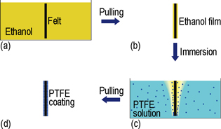
Figure S2 shows the process flow for the fabrication of a PTFE particle coating on a stainless-steel fiber felt. We connected the felt to a dipping machine to control the motion rate. First, the felt was immersed in ethanol and then taken out vertically at a speed of 1 cm/s. An ethanol film formed on the surface of the felt due to the excellent wettability of ethanol. We dipped the felt into the 9 wt% PTFE colloidal solution at specific rates as soon as possible. Subsequently, the felt was increased at a rate of 0.1 cm/s to avoid the detachment of the particles, and dried in air. During this process, the PTFE nanoparticles spontaneously moved to the felt surface under the effect of the tension gradient and formed a coating. In order to ensure the substrate was coated thoroughly with PTFE, an appropriate cycle number of above procedures was carried out. Finally, we sintered the felt coated with the PTFE coating up to 420 °C at a heating rate of 10 °C/min in a tube furnace (YG-1408, Shanghai Yu Zhi Electro Mechanical Equipment Co., Ltd.). The sample was maintained at that constant temperature for 70 min, during which the PTFE nanoparticles formed the nanofibers. The obtained sample was cooled down in the furnace.
Characterization
Scanning electron microscope (SEM, FEI Quanta 200 FEG, FEI Company) and atomic force microscope (AFM, Dimension Icon, Bruker Corporation) were used to image the morphologies of the PTFE coatings. The chemical compositions of the coatings were analyzed by using an energy dispersive spectrometer (EDS) equipped on the same SEM. The motion of the particles during the coating formation process was recorded by PIV (MicroVec, Inc., Beijing, China) from a side view. The PIV setup included a 532 nm diode pump solid state laser providing a maximum power of 5 W and a 640 × 480 resolution camera with a maximum capture rate of 258 fps, fitted with a 100 mm f/2.8 Tokina lens. The surface tension data were obtained using the hanging plate method with a Dataphysics OCA-20 analyzer (DataPhysics Instruments GmbH, Filderstadt, Germany). Water contact angles (WCAs) and water sliding angles (WSAs) were measured on a Dataphysics OCA 25 instrument (DataPhysics Instruments GmbH, Filderstadt, Germany) at room temperature. The volume of water used for measurements of WCAs and WSAs was 4.5 and 10 µL, respectively. WCAs and WSAs were the average values of measurements made at three different positions on the same samples. The measurements of Tafel plots were carried out with a three electrode electrochemical workstation (EG&G273A). The TGA data were obtained by using a thermogravimetric analyzer (TGA Q5000 IR, TA Instruments) at a heating rate of 10 °C/min under an air atmosphere. An electronic balance (FA2004N, Jinghai Instruments) weighed the water before and after oil–water separation.
Results and discussion
Self-assembly process of the PTFE nanoparticle coatings at the liquid–solid interface
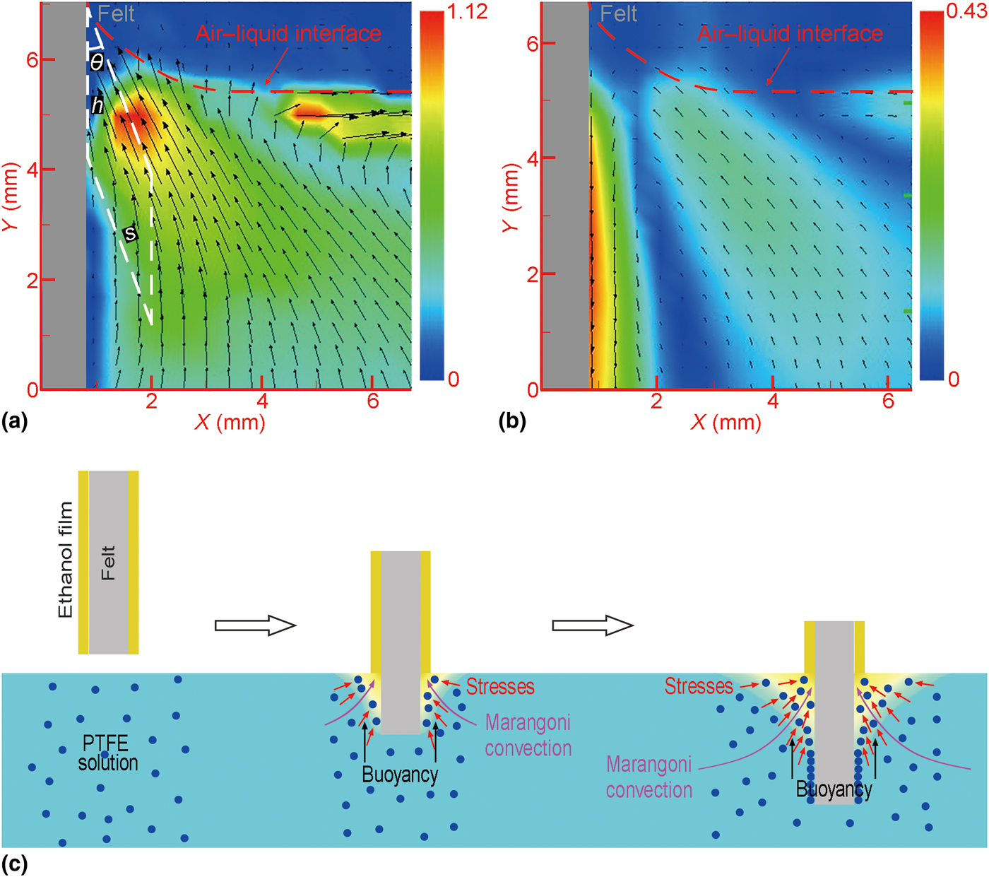
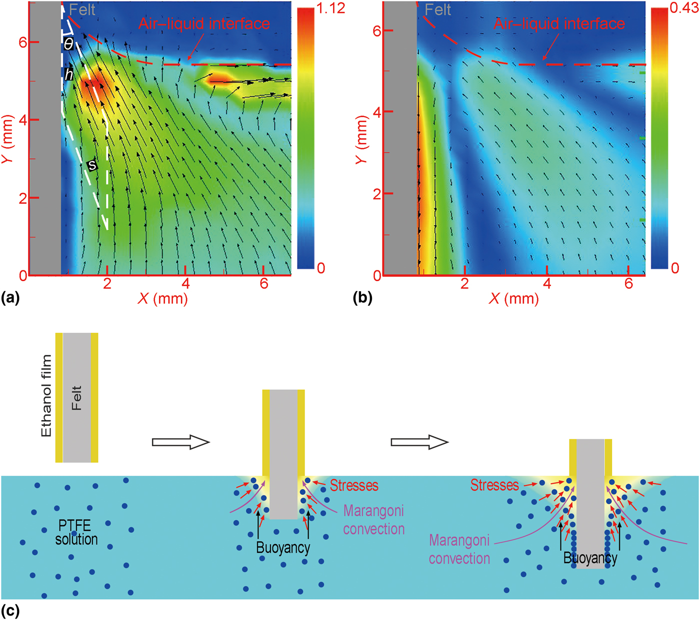
As shown in Fig. S3(a), a PTFE coating with limited defects was formed on the surface of the felt when the immersion velocity was 0.5 cm/s. If we directly immerse a dry felt into the PTFE colloidal solution at a speed of 0.5 cm/s, there were only few PTFE particles left on the surface [Fig. S3(b)]. We can conclude that ethanol plays a key role in the self-assembly process. To clarify the formation mechanism of the PTFE nanoparticle coating, the motion of the particles was recorded by PIV from a side view. The diameter of PTFE particles was too small to be observed. Thus, hydrophilic silica spheres with a diameter of 1.5 µm were dispersed in the mixture of water and ethanol (13:7, v/v) as an alternative, the concentration of which was 7.5 × 10⁻⁷ w/v. The surface tension of the mixture (32.79 mN/m) was almost equal to that of the 9 wt% PTFE solution (32.75 mN/m), which ensured the hydrophilic silica solution and the PTFE solution had similar properties. In the process of immersing the felt with an ethanol film into the solution, the particles continuously moved toward the surface of the felt in the vicinity of the air–liquid interface [Fig. 1(a)]. In contrast, we placed the dry felt into the colloidal solution, while other experimental conditions remained unchanged. Figure 1(b) shows that the motion direction of the particles near the felt was parallel to the surface of the felt because the immersion of the felt drove the downward motion of the liquid. Thus, the self-assembly occurs only if ethanol exists, the reason of which is attributed to three aspects [Fig. 1(c)]. First, ethanol will not sink into the colloidal solution during the immersion of the felt due to the effect of buoyancy. Second, at the air–liquid interface of two sides of the felt, a concentration distribution of ethanol from high to low is formed when ethanol starts to dissolve into the solution. Therefore, a surface tension gradient from low to high is generated because the surface tension of ethanol (22.3 mN/m) is much lower than that of the solution. Variations in the surface tension result in the Marangoni convection,[Reference Lu, Yang and Maa15,Reference Sha, Chen, Yin, Tu, Ye and Zheng16] which drives the particles to move. Third, within a certain depth below the liquid level, the concentration of ethanol is higher at the position closer to the liquid–solid interface because of the dissolution process. The tension becomes lower and lower from the interior of solution to the interface. The particles move relative to the liquid due to the stresses resulting from the variations of tension at the particle surfaces.[Reference Young, Goldstein and Block17,Reference Feng, Weng and Wang18] As a result, the PTFE particles can move toward and be adsorbed on the surface of the felt by van der Waals forces.
Motion of particles during the immersion of the felts (a) with and (b) without an ethanol film. The direction of the arrows indicates the motion direction of the particles. The color scale bars show the magnitude of the velocity (cm/s). The velocity distribution near the contact region between the felt and the air–liquid interface is missing because the meniscus reflects light. (c) Schematic illustration of the mechanism for particles moving toward the surface of the felt.
We also found that the immersion velocity of the felt was another parameter that could influence the formation of the PTFE coatings. The felts were immersed into the 9 wt% PTFE solutions at rates of 0.1, 0.3, 0.5, and 0.7 cm/s, respectively. The SEM images (Fig. S4) show the coverage ratios of the PTFE coatings on the surfaces of the metal microfibers at four different immersion rates. The rates corresponding to the coverage ratios from high to low were 0.5, 0.1, 0.3, and 0.7 cm/s in turn. According to the theoretical analysis in the Supplementary Information, the number of particles which are assembled on the per unit area of the substrate, ε, is expressed as
 $$\varepsilon = \alpha \eta \displaystyle{{hv_{\rm p}\sin \theta} \over {v_{\rm s}}}$$
where α is the proportion of the particles assembled on the substrate, η refers to the number of particles per unit volume, θ [an angle of the parallelepiped frame in Fig. 1(a)] represents the average motion angle of the particles which can reach the substrate, v p is the average velocity of the particles which can reach the substrate, v s denotes the immersion velocity of the substrate, and h is the depth at the liquid level, within which the particles move toward the substrate. α and η are thought to be constants. Table SI lists the data of v p, θ, and h corresponding to different values of v s. θ and h increase with the increase of v s because the acceleration of ethanol supply leads to the improvement of the tension gradient. However, the tendency is different for v p. When v s is 0.5 or 0.7 cm/s, the downward motion of the liquid in the vicinity of the substrate [Fig. 1(b)] weakens the obliquely upward motion of the particles to some extent. The calculated values of ε in Table SI agree with the observation in Fig. S4. To maximize the efficiency of the self-assembly, the immersion rate of the substrate was fixed at 0.5 cm/s in the subsequent experiments.
Effect of the species of the low surface tension liquids on the self-assembly process
Besides ethanol, other low surface tension liquids miscible with water can also be used to induce the self-assembly. Here, we replaced ethanol by methanol and n-propanol. The immersion velocity of the felts was 0.5 cm/s and other experimental parameters remained the same. The coverage rate of the PTFE particles decreased in the order: methanol > ethanol > n-propanol [Figs. S4(c) and S6]. This was reflected in the data of ε [Tables SI and SII], which were obtained by the PIV observation [Figs. 1(a) and S7]. Physical properties of three liquids are listed in Table SIII. The densities of the liquids are similar, and thus the influence of buoyancy can be ignored. The motion of the particles mainly depends on the tension gradient. According to the theoretical analysis in Ref. Reference Lu, Yang and Maa15, the tension gradients produced by methanol and n-propanol are maximum and minimum, respectively. Even though methanol was more conducive to the self-assembly, ethanol was used in the following experiments because of low toxicity and accessibility.
Superhydrophobicity and superoleophilicity of the PTFE-coated felts
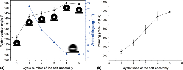
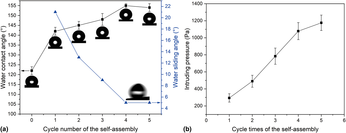
The surface wettability of the felts was estimated by the measurements of water and oil contact angles. The bare felt showed intrinsic hydrophobic property with WCA of 122° [Figs. 2(a)]. In order to protect the PTFE nanoparticle coating against damage from water and acquire a stable wettability, we sintered the sample in Fig. S3(a) at 420 °C for 70 min. The PTFE particles were transformed into nanofibers, the mechanism of which was reported in Refs. Reference Chen, Du, Weng, Mahmood, Feng and Wang12, Reference Luo, Zhang, Hu, Liu, Guo, Zhang and Wang19, and Reference Luo, Zhang, Wang, Liu and Xue20. However, the WCA was just 145° and the WSA was 21° [Fig. 2(a)], which could be attributed to the imperfect coverage of the nanofibers. To improve the hydrophobicity, an appropriate cycle number of the self-assembly in Fig. S2 was carried out. With the increase of cycle number, the WCA increased and the WSA decreased [Fig. 2(a)]. Additionally, the intruding pressure of water is another important parameter to characterize the performance of the materials for oil–water separation, which indicates the maximum height of water the felts can support.[Reference Zhang, Liu, Cao, Chen, Xu, Lin and Feng21] The average intruding pressure for water from five repeated experiments is shown in Fig. 2(b). The measured intruding pressure of the coated felts increased with the increase of cycle number. When the cycle number was four, the intruding pressure and the superhydrophobicity (WCA = 155° and WSA = 5°) were high enough to separate oil and water. Consequently, the self-assembly process was cycled four times in the follow-up experiments. A jet of water could bounce off the PTFE-coated felt without leaving any residual, implying the weak interaction between water and the felt (Fig. S8). The SEM images of the bare felt and the felt coated with PTFE nanofibers are shown in Fig. S9. It could be seen that the bare felt was consisted of cross-connected metal microfibers with smooth surfaces. After the self-assembly and sintering process, all the metal microfibers were wrapped by dense layers of the interconnected PTFE nanofibers. The surface chemical compositions of the bare and coated felts were examined by EDS [Figs. S9(c) and S9(f)]. The spectrum of the bare felt showed peaks for iron (61.42%, relative atomic number percentage by element), chromium (17.78%), and carbon (7.02%). An EDS scan of the PTFE-coated felt yielded the peaks for fluorine (46.22%), carbon (33.06%), iron (13.73%), and chromium (4.28%). The appearance of fluorine peak and the increase of carbon content are attributed to PTFE. In Fig. S10(a), an AFM image reveals the morphology of the unsintered PTFE particle coating. The corresponding surface roughness profile is shown in Fig. S10(b). Figure S10(c) shows the morphology of the sintered PTFE nanofiber coating. The surface had a higher roughness after sintering because of the appearance of the nanofibers and the microbumps [Fig. S10(d)]. The hierarchical micro/nano-roughness complements the roughness provided by the metal microfibers, which meets the requirement for the morphology of superhydrophobicity. One can see that the felts coated with the PTFE nanofibers possess the superhydrophobic properties because of hierarchical micro/nano-scale structures and the low-surface energy of PTFE.[Reference Accardo, Shalabaeva, Di Cola, Burghammer, Krahne, Riekel and Dante22] On the contrary, when an oil droplet (carbon tetrachloride) was dropped onto the PTFE-coated felt, it quickly spread on the surface, which showed the superoleophilic property [Figs. S11(a) and S11(b)]. When more oil was dropped, it permeated the felt after the adsorption capacity limitation [Fig. S11(c)].
(a) The effects of the cycle number of the self-assembly on the WCA and WSA of the coated felt. (b) The relationship between the cycle number of the self-assembly and the intruding pressure.
Oil–water separation
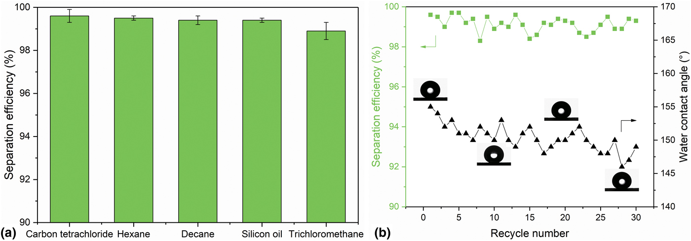
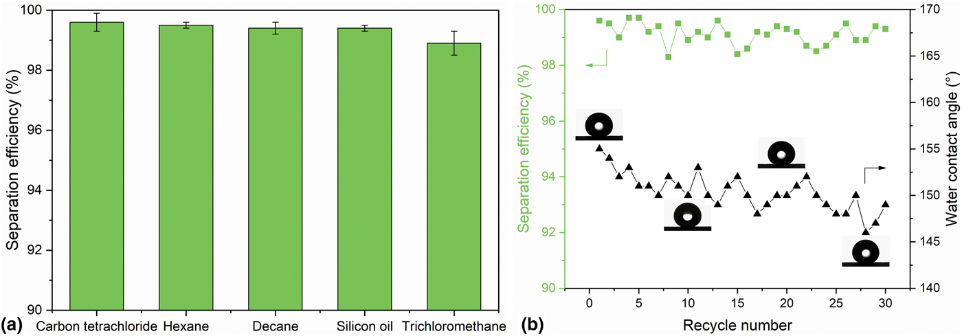
Based on the superhydrophobicity and superoleophilicity, the PTFE-coated felt was utilized to separate oil and water. To illustrate the applicability of the PTFE-coated felt for oil–water separation, a series of experiments were carried out as shown in Fig. S12. The felt was fixed between two glass tubes and the mixture of 10 mL water and 10 mL carbon tetrachloride (dyed with Oil Red O) was poured out of a glass beaker into the upper tube. Carbon tetrachloride (red) passed through the PTFE-coated felt and dropped into the beaker underneath, while water remained on the top of the felt inside the upper tube. The separation process had no need of external force but only gravity, benefiting from the macro-porous structures of the felt. For oil with lower density than water, equipment was tilted to ensure the oil came in contact with the felt before water.[Reference Xue, Sun, Cao, Chen, Tao, Li, Feng, Fu and Wei23] Thus, other types of mixtures including hexane/water, decane/water, silicon oil/water, and trichloromethane/water were also successfully separated. The separation efficiency was calculated according to the equation:  $\gamma = m/m_0 \times 100\% $, where γ is the separation efficiency, m is the mass of the water after separation, and m 0 is the mass of the water before separation.[Reference Pi, Hou, Zhou, Li, Wen, Xu, Cheng and Wang24] In Fig. 3(a), the separation efficiencies for a selection of oil–water mixtures were all above 98%. Nearly no water in the collected oil or oil in the collected water could be seen. Moreover, the impact of recycle number of the carbon tetrachloride/water separation on the superhydrophobicity of the PTFE-coated felt was investigated to assess the recyclability. After each separation experiment, the felt was cleaned thoroughly by ethanol and water to remove the absorbed oil and then dried in an oven at 60 °C for 30 min. The WCA decreased to 149° after 30 recycles of the separation experiments, which might be caused by the residual oil on the felt [Fig. 3(b)]. However, the separation efficiency had no obvious change and was still higher than 98%. As a result, the PTFE-coated felts have excellent repeatability for oil–water separation.
(a) The separation efficiency of the coated felt for a selection of oil–water mixtures. (b) Effect of recycle number on the separation efficiency and the WCA of the coated felt.
Evaluation of the stability
In practical applications, the stability of the materials for oil–water separation has great significance. Thus, abrasion test and environmental durability tests were performed. Figure S13(a) shows the method of the abrasion test. The coated felt was pressed against a 1200 mesh sandpaper using a 100 g weight. Then, the felt was moved forward and backward on a 20-cm cycle. The WCA decreased below 150° after three scratch cycles [Fig. S13(b)]. The felt still kept the water repellence and the WCA was higher than that of the bare felt after 30 scratch cycles. We used another coated felt to conduct the oil–water separation after scratch cycles. The separation efficiency was above 98% in all experiments. As a result, the oil–water separation performance of the felt is durable.
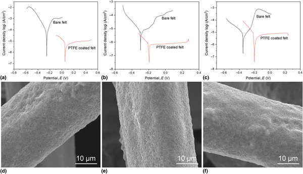
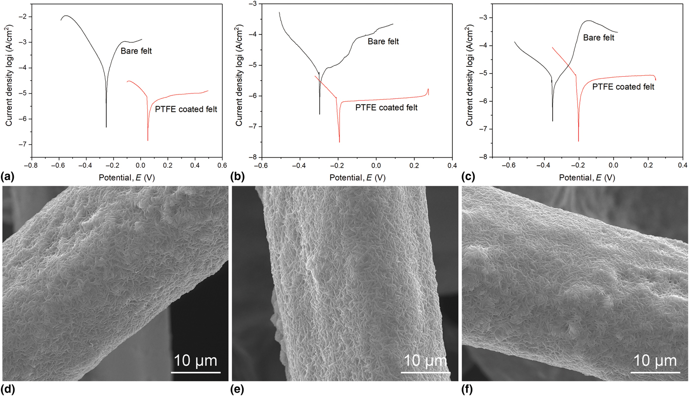
In order to study the chemical stability, we dripped the corrosive liquids including acid (0.5 M H2SO4), salt (3.5 wt% NaCl), and alkaline (1 M NaOH) aqueous solutions on the surface of the PTFE-coated felt. All the CAs tested with above solution drops were not less than 150° with the SAs of 6°–7° (Fig. S14). As shown in Figs. 4(a)–4(c) and Table SIV, the corrosion characteristics of the bare and coated felts in 0.5 M H2SO4 solution, 3.5 wt% NaCl solution, and 1 M NaOH solution were investigated by polarization measurements. For each solution, the i corr values of the bare felts were higher. When the bare felts are immersed in the corrosive solutions, the oxide films are destroyed and iron is subject to ionization, resulting in the corrosion of the surfaces. Meanwhile, the corrosive potentials of the PTFE-coated felts shifted in the positive direction, which demonstrated that the PTFE coatings acted as the effective anodic protection rather than the sacrificial corrosion protection.[Reference Yu and Guo25] The formation of the superhydrophobic coatings on the felts has two effects on the improvement of corrosion resistance. On the one hand, air is trapped in the cavities of the PTFE-coated felts and segregates the solutions and the felts, which is consistent with the Cassie–Baxter model.[Reference Roach, Shirtcliffe and Newton26] On the other hand, the PTFE coatings act as effective barriers to the inward diffusion of corrosive ions. Furthermore, the PTFE-coated felts were immersed in the above three solutions for 100 h, respectively. Figures 4(d)–4(f) indicate that the surfaces of the coated felts had no obvious change. All the results illustrate that the PTFE-coated felts possess the superb chemical stability.
Tafel plots of the bare and coated felts in (a) 0.5 M H2SO4, (b) 3.5 wt% NaCl, and (c) 1 M NaOH aqueous solutions. SEM images of the coated felts after being immersed in (d) 0.5 M H2SO4, (e) 3.5 wt% NaCl, and (f) 1 M NaOH aqueous solutions for 100 h.
In addition, the thermal stability of the PTFE-coated felts was studied by thermogravimetric analysis [Fig. S15(a)]. When the temperatures were below 475 °C, the PTFE-coated felt showed a stable state and the weight was almost the same. At the temperatures above 475 °C, PTFE began to decompose leading to the weight loss. When the PTFE-coated felts were placed in the furnace and sintered at 440 °C for a few hours, they still had excellent hydrophobicity and the oil–water separation efficiency nearly remained unchanged [Fig. S15(b)]. Therefore, the fine properties of PTFE[Reference Bi and Mueller27] endow the felts with outstanding environmental stability and potential in industrial applications.
Conclusions
In summary, we present a facile method to create durable superhydrophobic and superoleophilic coatings on the stainless-steel fiber felts via tension gradient self-assembly. The felt with an ethanol film was vertically placed into the PTFE solution (9 wt%) at a speed of 0.5 cm/s. The tension gradient appeared as a result of the dissolution of ethanol into the solution, and induced the Marangoni convection and the relative motion between the solution and the PTFE nanoparticles. The particles moved toward the surface of the felt and formed a coating. Besides ethanol, other low surface tension liquids such as methanol and n-propanol can also induce the self-assembly. The sample was sintered at 420 °C for 70 min, followed by cooling. During the sintering process, the PTFE particles melted and rearranged to form nanofibers. As a result, the PTFE nanofibers not only offered low-surface energy, but also provided nanoscale roughness, which was beneficial for the oil–water separation. The felts coated with nanofibers could separate a series of oil–water mixtures with efficiencies over 98%. The separation efficiency was still stable after the sample was reused for oil–water separation over 30 times. Moreover, the sample worked well under extreme environmental conditions of strong corrosive solutions and high temperatures. We also notice that some more convenient methods, including triboelectric adhesion[Reference Bayer, Davis, Loth and Steele28] and dip casting,[Reference Bayer, Caramia, Fragouli, Spano, Cingolani and Athanassiou29] may be used in oil–water separation. However, the methods are usually applicable for the two-dimensional substrates. By comparison, our approach has the potential in the self-assembly of PTFE particles on the three-dimensional porous substrates such as polyurethane foams, which can adsorb oil from contaminated water.
Supplementary material
The supplementary material for this article can be found at https://doi.org/10.1557/mrc.2019.65
Acknowledgments
This research was funded by the National Natural Science Foundation of China (Grant Nos. 51775296, 51375253, 51703116, and 20171301886). The authors also acknowledge the support of this work from the State Key Laboratory of Tribology, Tsinghua University, China, under grant codes SKLT2017C06 and SKLT2018C06.