Introduction
The recent progress in construction of single-crystal diffractometers with area detectors, and in electron diffraction tomography (EDT) allows not only quick data collection for crystal-structure refinements, but also reciprocal space imaging. The creation of user-defined reciprocal space (RS) sections – equivalents of precession photographs – allows quick and clear visualization of the reciprocal lattice as such, as well as of various phenomena such as diffuse scattering, modulation, twinning, and polytypism. Some minerals and other compounds affected by the polytypism might form a variety of polytypes in the same occurrence and/or in a synthetic run product, rarely even inside the same individual crystal. The study of polytypism thus requires routine checking of many specimens, typically several tens or hundreds. Modern diffractometers or electron microscopes enable this to be done in a reasonable time.
Several detailed studies of the polytypism of the layered silicate cronstedtite from various natural occurrences such as Pohled (Czech Republic), Nižná Slaná (Slovakia), Chyňava (Czech Republic) (Hybler et al., Reference Hybler, Sejkora and Venclík2016, Reference Hybler, Števko and Sejkora2017; Hybler & Sejkora, Reference Hybler and Sejkora2017), and Nagybörzsöny, Hungary (Hybler et al., Reference Hybler, Dolnícek, Sejkora and Števko2020) have been published recently. EDT and/or 3D electron diffraction studies of submicroscopic crystals separated from synthetic run products were reported by Pignatelli et al. (Reference Pignatelli, Mugnaioli, Hybler, Mosser-Ruck, Cathelineau and Michau2013, Reference Pignatelli, Mosser-Ruck, Mugnaioli, Sterpenich and Gemmi2020) and Hybler et al. (Reference Hybler, Klementová, Jarošová, Pignatelli, Mosser-Ruck and Ďurovič2018). RS sections were reproduced and interpreted in order to prove polytypes in most of these studies. Cronstedtite from meteorites was studied by electron diffraction by Pignatelli et al. (Reference Pignatelli, Marrochi, Vacher, Delon and Gounelle2016, Reference Pignatelli, Marrocchi, Mugnaioli, Bourdelle and Gounelle2017, Reference Pignatelli, Mugnaioli and Marrocchi2018).
Cronstedtite was first described by Steinmann (Reference Steinmann1820, Reference Steinmann1821), from the Vojtěch Mine in Příbram (now Czech Republic) and was named in honor of the Swedish chemist and mineralogist, Axel Fredrik Cronstedt (1722–1765). Later it was found in Rejské Lode in Kaňk, near Kutná Hora (formerly known also as Kuttenberg, now Czech Republic) by Vrba (Reference Vrba1886). Early studies dealing with polytypism of this mineral were reported by Frondel (Reference Frondel1962), Steadman and Nuttall (Reference Steadman and Nuttall1963, Reference Steadman and Nuttall1964), Steadman (Reference Steadman1964), and later by Bailey (Reference Bailey1969, Reference Bailey and Bailey1988). They recognized cronstedtite as a T–O or 1:1 trioctahedral phyllosilicate of the serpentine-kaolinite group. The 1:1 structure building layer is composed of tetrahedral and brucite-like octahedral sheets connected via shared apical oxygen atoms of octahedra. The neighboring layers are connected via hydrogen bonds, where OH groups of the octahedral sheets are donors, while the basal oxygen atoms of adjacent tetrahedral sheets are acceptors. The general formula is (Fe2+3–x Fe3+ x )(Si2–x Fe3+ x )O5(OH)4, where 0 < x < 0.85. The partial substitution of Fe3+ for Si4+ in tetrahedral sites is characteristic of this mineral. Presumably the deficiency of charge due to this substitution is compensated by the substitution of Fe3+ for Fe2+ in octahedral sites. Moreover, substitutions of Mn and/or Mg for Fe2+ in octahedral sites are known from several localities. The extreme Mn-rich analogue of cronstedtite was approved as a distinct mineral species, guidottiite (Wahle et al., Reference Wahle, Bujnowski, Guggenheim and Kogure2010).
According to Dornberger-Schiff and Ďurovič (Reference Dornberger-Schiff and Ďurovič1975a, Reference Dornberger-Schiff and Ďurovič1975b), 1:1 layer silicates can be regarded formally as OD structures of three kinds of polar layers, category II (Ďurovič, Reference Ďurovič and Merlino1997a). These three kinds of layers are: (1) Tetrahedral (T) OD layer, comprising the whole tetrahedral sheet including the plane of apical O atoms and OH groups of the octahedral sheet at the side close to the tetrahedral sheet; (2) octahedral (O) OD layer comprising only the plane of central cations of octahedra; and (3) OH layer comprising the plane of OH groups of the octahedral sheet at the side opposite to the tetrahedral sheet. The symbol of the OD groupoid family (Grell & Dornberger-Schiff, Reference Grell and Dornberger-Schiff1982) reads as:

where H in layer group symbols of OD layers means centered cell with centering points at
$$\raisebox{1ex}{$1$}\!\left/ \!\raisebox{-1ex}{$3$}\right.$$
 ,
$$\raisebox{1ex}{$2$}\!\left/ \!\raisebox{-1ex}{$3$}\right.$$
 , 0, and
$$\raisebox{1ex}{$2$}\!\left/ \!\raisebox{-1ex}{$3$}\right.$$
 ,
$$\raisebox{1ex}{$1$}\!\left/ \!\raisebox{-1ex}{$3$}\right.$$
 , 0, and the symbol in parentheses indicates the direction lacking periodicity.
These three OD layers (in the order T–O–OH) form the so-called OD packet (Ďurovič, Reference Ďurovič1974), corresponding exactly to the 1:1 layer (i. e. the structure building layer). The symmetry of the OD packet is expressed by the layer group P(3)1m (Dornberger-Schiff, Reference Dornberger-Schiff1964). In International Tables Vol. E (Reference Kopský and Litvin2010), the layer-group symbol reads p31m. All polytypes are formally derived by stacking of equivalent OD packets according to rules corresponding to four subfamilies (Bailey’s groups) A, B, C, D. In the packet the hexagonal protocell, a = 5.50, c = 7.10 Å, can be defined. Alternatively, the orthohexagonal cell a = 5.50, b = 9.50, c = 7.10 Å is often used. The whole OD packet (1:1 layer) is presented in Fig. S1 in Supplementary Material. Possible interlayer shift vectors are displayed in Fig. 1, and referred to as hexagonal and orthohexagonal basic vectors.
Derivation of symbolic figures. Upper: possible stacking vectors with respect to hexagonal protocell and orthohexagonal cell. In the middle: part of the 1:1 layer in two possible positions, e, u (meaning even and uneven, respectively), with triangles made by unshared edges of octahedra around local triads indicated in red. Lower: symbolic figures – equilateral triangles identical to those in the middle, with possible stacking vectors indicated. Stacking rules for subfamilies – Bailey’s groups are summarized below

A common practice is to represent pictures of OD structure models by appropriately chosen symbolic figures. Such figures simplify substantially the structure model(s) while retaining the important structural features, mainly local and total symmetry. For trioctahedral 1:1 structure building layers – OD packets, these figures are equilateral triangles in the same orientation as triangles made by unshared octahedral edges on the OH layer around the local triads: ∇ and Δ for two possible orientations of the OD packet (1:1 layer), e and u, meaning even and uneven, respectively. They also correspond to the occupancy of octahedral cation sets II and I, respectively. These symbolic figures are used in structure models of polytypes throughout this study. The stacking rule of the subfamily A is characterized by the ensemble of ±ai/3 shifts of consecutive 1:1 layers (without any rotation). The allowed shifts are <0>, <2>, <4> for the e setting, and <1>, <3>, <5> for the u setting of the 1:1 layer. The stacking rule of the subfamily D is characterized by regular alternations of 180° rotations (i.e. e and u settings, II and I sets) of consecutive packets (structure building layers), combined with +b/3, –b/3, or zero interlayer shifts vectors (<+>, <–>, <*>, in Fig. 1). As a consequence, the even-layer polytypes (2, 4, 6, 8, etc.) are possible. In reality, the two- and six-layer polytypes have been found to date.
Sequences of packets (P 0; P 1; P 2;…. ) of polytypes are conventionally presented in the following way:

for the 3T polytype as an example. The e symbol in the upper line means one of two possible orientations e or u, and numbers in the lower line represents the respective shift vectors in Fig. 1.
Generally the RS sections corresponding to the following six reciprocal lattice planes should be recorded or generated: (
$$2h\overline{h}$$
 l hex)*, (hhl hex)*, (
$$\overline{h}$$
 2hl hex)*, (h0l hex)*, (0kl hex)*, and (
$$\overline{h}$$
 hl hex)*. Distributions of so-called subfamily reflections along the reciprocal lattice rows [2
$$\overline{1}$$
 l]* / [11l]* / [
$$\overline{1}$$
 2l]* in (
$$2h\overline{h}$$
 l hex)* / (hhl hex)* / (
$$\overline{h}$$
 2hl hex)* planes, respectively, are used to determine OD subfamilies (Bailey’s groups) A, B, C, D (Bailey, Reference Bailey1969, Reference Bailey and Bailey1988; Dornberger-Schiff & Ďurovič, Reference Dornberger-Schiff and Ďurovič1975a, Reference Dornberger-Schiff and Ďurovič1975b). Similarly, distributions of characteristic reflections along [10l]* / [01l]* / [
$$\overline{1}$$
 1l]* rows in (h0l hex)* / (0kl hex)* / (
$$\overline{h}$$
 hl hex)* RS sections were used to determine particular polytypes. For known polytypes, graphical identification diagrams were constructed for a simple visual comparison with actual diffraction patterns (Ďurovič, Reference Ďurovič1981, Reference Ďurovič1997b; Hybler et al., Reference Hybler, Klementová, Jarošová, Pignatelli, Mosser-Ruck and Ďurovič2018; Mikloš, Reference Mikloš1975; Weiss & Kužvart, Reference Weiss and Kužvart2005). They are presented (in an extended form, with two diagrams added) in Fig. 2 together with the table for polytype determination. These diagrams are valid for all trioctahedral serpentine minerals.
Extended identification diagrams of subfamilies (top left), polytypes (top right), and the identification table (below). The sizes of circles are proportional to the intensities of reflections in reciprocal lattice rows. The [00l]* row in the middle corresponds to the 7.1 Å periodicity of the protocell, which is the same in all subfamilies and polytypes, and thus serves as a common scale for evaluation of RS sections

Some of the polytypes in the table in Fig. 2, namely 1M, 2M 1, 3T, 2O, 2M 2, 6H 1, 1T, 3R, 2T, 2H 1, 2H 2, and 6R 1 are so-called MDO polytypes (abbreviation of: Maximum Degree of Order), known also as standard, simple, or regular (Dornberger-Schiff, Reference Dornberger-Schiff1982). In these polytypes, all triples of equivalent layers (or packets) are geometrically equivalent and cannot be decomposed into fragments of “simpler” polytypes. The remaining ones are so-called non-MDO polytypes, where this condition is not satisfied. Some of them are included in Fig. 2. In the present study, both kinds of polytypes are presented.
Structures of polytypes recognized later as 1T, 2H 1, 3T, 6R 2 were determined roughly by Steadman and Nuttall (Reference Steadman and Nuttall1963), and of 2H 2, 1M, 2M 1, 2T by Steadman and Nuttall (Reference Steadman and Nuttall1964). Later, Steadman (Reference Steadman1964) derived 20 theoretical structures based on variable stacking sequences. Refinements of the following polytypes were published to date: 1T (Hybler et al., Reference Hybler, Petříček, Ďurovič and Smrčok2000), 2H 2(Geiger et al., Reference Geiger, Henry, Bailey and Maj1983; Hybler et al., Reference Hybler, Petříček, Fábry and Ďurovič2002), 3T (Smrčok et al., Reference Smrčok, Ďurovič, Petříček and Weiss1994), 1M (Hybler, Reference Hybler2014), and 6T 2(Hybler, Reference Hybler2016).
In many crystals, polytypes do not occur isolated, but in oriented crystal associations known as allotwins (Nespolo et al., Reference Nespolo, Kogure and Ferraris1999). Some even include twins of a polytype allotwinned with another polytype. In the RS sections of twinned and allotwinned crystals, diffraction patterns of all components are superimposed.
The aim of this paper was to present a detailed study of numerous cronstedtite polytypes and their allotwins, separated from the unique sample from Ouedi Beht, Morocco.
Materials and Methods
Materials
Occurrence
The samples with cronstedtite were collected in 2017 by local people digging for mineral specimens from the hydrothermal veins with pyrite and calcite hosted in a skarn body situated at the base of the El Hammam hill (Djebel el Hammam), close to the Wadi (Ouedi) Beht (Beht river) and not far from the El Hammam fluorite deposit, which is located ~45 km SW of Meknès in the northeastern part of the Variscan Moroccan Central Massif in northern Morocco. The approximate position of the locality is indicated in the outline map in Fig. 3. No more specimens with cronstedtite have been collected since 2017 so it seems to be a small and extremely limited find.
Outline map of Morocco with the sample locality indicated. Some important cities are indicated also

The area around El Hammam consists predominantly of Paleozoic (Ordovician to Carboniferous) shales, quartzites, and limestones (Izart et al., Reference Izart, Chevremont, Tahiri, El Boursoumi and Thieblemont2001). The hydrothermal veins with fluorite and sulfides at the El Hammam fluorite deposit are hosted in Carboniferous limestones (Chbihi & Gmira, Reference Chbihi and Gmira1998; Jébrak, Reference Jébrak1985). Small surface outcrops of the evolved peraluminous El Hammam monzogranite are located in the western part of the area representing offshoots of a much larger hidden granitic intrusion (Agard, Reference Agard1966; Izart et al., Reference Izart, Chevremont, Tahiri, El Boursoumi and Thieblemont2001; Jébrak, Reference Jébrak1985). This Hercynian late-orogenic intrusion is responsible for a large halo of thermal metamorphism and development of numerous skarn bodies with Sn-W-B and sulfidic mineralization as well as extensive zones of tourmalinization (Aissa, Reference Aissa1997; Mahjoubi et al., Reference Mahjoubi, Chauvet, Badra, Sizaret, Barbanson, El Maz, Chen and Amann2015; Sonnet, Reference Sonnet1981). Other magmatic rocks present within the El Hammam area are dolerite, microgranite, and rhyolite dykes that are mostly oriented parallel to the strike of rock of the Paleozoic series (Izart et al., Reference Izart, Chevremont, Tahiri, El Boursoumi and Thieblemont2001).
Sample
A rounded piece of the skarn ore material, 10 cm×8 cm×5.5 cm, containing pyrite, quartz, calcite, siderite, and cronstedtite was purchased by the last listed author (MŠ) from Jordi Fabre (Fabre Minerals) for the National Museum Prague, where it is stored under the catalogue number P1N 114314 (Fig. 4). Cronstedtite is present in several distinct parts of the sample. The central part (CP in the following) represents a core built of charcoal-like massive aggregate of cronstedtite intersected by several cracks and veinlets filled with pyrite, calcite, and quartz. Under the microscope, fibrous aggregates are visible. (Fig. 4b). This core is encircled by a zone built of pyrite, quartz, and siderite. It is followed by a double vein (in the following internal vein (IV)) of euhedral single crystals. In Fig. 4c a detail of this vein is presented. On the opposite side of the sample two smaller outer veins (OV1 and OV2) were recognized, as well as a cavity with druses of crystals (Back Druses, BD). On the lateral part of the sample is another cavity (with Side Druses, SD). Small pieces of crystalline material were removed separately from the massive aggregate, veins, and cavities mentioned above. These samples were handled separately in order to cover eventual differences in polytypism and chemical composition. Single crystals for further studies were selected under the stereomicroscope and labeled according to their origin, e.g. CP-1, CP-2, etc. from the central part, IV-1, IV-2, etc. from the inner vein and so on.
Photographs of a the whole sample; b detail of the fibrous aggregate from the central part; c detail of the internal vein. Legend: CP – cronstedtite, central part, IV– cronstedtite, internal vein, cal – calcite, qz – quartz, py – pyrite, sd – siderite, A – single crystals with the form typical of the A subfamily. Other recognizable crystals belong to subfamily D. (Photos by Pavel Škácha)

Single Crystal X-ray Diffraction
Selected crystals of cronstedtite were glued onto glass fibers under the stereomicroscope. The common cyanoacrylate superglue was used for this purpose. Then they were tested with the aid of a four-circle (double-wavelength) X-ray diffractometer Gemini A Ultra (Rigaku Oxford Diffraction, Wrocław, Poland) equipped with the CCD area detector Atlas S2 (Agilent Technologies, Santa Clara, California, USA) in the Institute of Physics, Czech Academy of Sciences. MoKα radiation with a graphite monochromator, λ=0.71070 Å, and Mo-enhanced fiber optics collimator were used. Some small, weakly diffracting crystals were studied with the aid of the more powerful four-circle SuperNova diffractometer (also manufactured by Rigaku Oxford Diffraction, Wrocław, Poland) equipped with the microfocus X-ray tube – about ten times more intense than that of the Gemini A Ultra. The same Atlas S2 CCD area detector was used.
A pre-experiment was performed in order to set parameters for the full experiment. Then a quick full experiment, with some parameters reduced (mainly exposure time) was started. Typically, ~450–500 frames were recorded. The total experiment time varied from 10 to 100 minutes.
The CrysAlisPro, version 171.40 (Rigaku Oxford Diffraction, 2018) package was used for the data collection, unit-cell parameters calculation, and processing of data recorded by both diffractometers. The allotwins of the subfamilies A and D were at first indexed formally in the three- or six-layer hexagonal cells, respectively. The “unwarp” procedure then created user-defined RS sections. The OD subfamilies (Bailey’s groups) and polytypes were determined from RS sections. For known polytypes, graphical identification diagrams in Fig. 2 were used. For other polytypes, identification diagrams were constructed. Unit-cell parameters of polytypes were then calculated.
However, diffraction patterns in RS sections of some allotwins containing too many polytypes were almost impossible to interpret. Fortunately, owing to the excellent cleavage, such crystals were cut under the stereomicroscope into smaller fragments, typically four. The crystal glued previously on the glass fiber was put carefully into the drop of the solvent on the glass plate and released from the fiber. Then a new portion of the glue was put into the drop. As soon as the glue became highly viscous, but not completely dry, the crystal was cut into fragments using a razor blade. Again, the drop of glue was diluted by the solvent and the surplus of the liquid was wicked out carefully by a stick of absorbent cotton. Cleaved fragments were separated by a needle, glued one by one onto glass fibers, and studied separately afterwards. Since some of them still produced complex diffraction patterns, the cleaving procedure had to be repeated, in rare cases even more than once. In this way, many polytypes were successfully separated mechanically and identified. The distribution of polytypes in some complicated allotwins is described and discussed below.
Rarely, small crystals were found attached on the surfaces of larger ones. They were detached carefully under the stereomicroscope and also studied separately.
For some promising crystals, full experiments were repeated with modified parameters, mainly longer exposures and finer binning, in order to record datasets for crystal-structure refinements and/or more precise and less noisy images of RS sections. More than 300 specimens including cleaved fragments and detached crystals were studied by X-ray diffraction. Unit-cell parameters of selected crystals including some cleaved fragments are presented in Table 1; the complete list of cell parameters of all crystals studied is available in Table S1 in the Supplementary Materials.
Unit-cell parameters (in Å or degrees, with standard uncertainties in parentheses), OD subfamilies (Bailey’s groups), and polytypes of selected crystals of cronstedtite from Ouedi Beht, Morocco. Polytypes occurring as minor parts of allotwins in given samples are in parentheses

Space groups of polytypes: 3T, 6T 2: P31; 1M: Cm; 2M 1: Cc; 2H 1: P63 cm; 2H 2, 6H 2: P63; 6R 1: R3c; 6R 2: R3; 6T 1, 6T 3, 6T 4, 6T 5, 6T 6: P3.
Tex. means Textured sample. Peak, Top, Middle, Middle 1, Middle 2, Bottom etc. - respective parts of cleaved crystals. EPMA - the specimen was later sent for electron probe microanalysis. Twin 180°, 120° – crystal twinned by respective rotation angle.
Electron Probe Microanalysis
The selected fragments of cronstedtite crystals (21 altogether), in which polytypes were determined, were mounted on epoxy discs, polished by diamond suspensions, and coated with a carbon layer ~30 nm thick. The polished grains were analyzed at the National Museum in Prague using a CAMECA SX-100 electron probe micro analyzer (CAMECA, Société par Actions Simplifiée (SAS), Gennevilliers, France) operating in wave-dispersive (WDS) mode with an acceleration voltage of 15 kV, beam current of 10 nA, and beam diameter of 5 μm. The following standards and analytical lines were used: hematite (FeKα) albite (NaKα), fluorapatite (PKα), celestite (SKα), diopside (MgKα), halite (ClKα), chalcopyrite (CuKα), LiF (FKα), rhodonite (MnKα), sanidine (KKα, SiKα, AlKα), wollastonite (CaKα), and ZnO (ZnKα). The peak counting times were between 10 and 20 s and half of the peak time was used for both background positions. The raw counts were converted to wt.% using the standard PAP procedure (Pouchou & Pichoir, Reference Pouchou, Pichoir and Armstrong1985). Oxygen was calculated from stoichiometry. The above-listed elements, which are not included in the tables, were, in all cases, below the limits of detection. The H2O, Fe2+, and Fe3+ contents as well as x-values were calculated on the basis of the general formula of cronstedtite (Fe2+3-x Fe3+x)(Si2-xFe3+x)O5(OH)4. 164 point analyses were performed.
RESULTS AND DISCUSSION
All polytypes identified in the Ouedi Beht sample belong to OD subfamilies (Bailey’s groups) A and D. In most cases, both kinds of crystals are recognizable by morphology at first glance. The A-group crystals are represented by trigonal pyramids, slim trigonal pyramids, sometimes truncated, rarely needles with triangular cross-sections. The D group crystals form hexagonal pyramids, sometimes truncated, with rounded edges between pyramidal faces changing the shape close to cone. Smaller crystals are almost perfectly conical. Larger crystals often have complicated fractal cross-sections close to base. Cylindrical, acicular, plate-like or lath-shaped crystals are also present. Some typical crystal forms are shown in Fig. 4.
Subfamily A Polytypes
These polytypes occur mostly in the internal vein, in both side veins, and, exceptionally, in the side druse. They were not found in the central part and back druse. As a whole they are less frequent in the occurrence.
The following polytypes were detected in the sample: 2M 1, 1M, 3T, and 6T 2. Almost all crystals of the A group are allotwins, containing more than one polytype. Moreover, twinning by reticular pseudo-merohedry of monoclinic polytypes with ±120° rotation about chex as twin operation is widespread. Another kind of twinning with 180° (or, more generally (2n+1)×60°) rotation about chex as twin operation is less common. This operation exchanges obverse/reverse settings of the rhombohedral subfamily structure. These twins are commonly, but not quite correctly, referred to as “obverse-reverse twins” (Ferraris et al., Reference Ferraris, Makovicky and Merlino2008, chapter 5.1.2.4). The subset of subfamily reflections with rhombohedral symmetry is superimposed with its mirror image in RS sections (Hybler et al., Reference Hybler, Sejkora and Venclík2016, Reference Hybler, Števko and Sejkora2017). In this kind of twin from the Oedi Beht occurrence, one twin individual is very dominant, while the second is present in minute amounts.
The rare 2M 1 polytype, a = 5.49, b = 9.51, c = 14.40 Å, β = 97.30°, space group Cc, was successfully selected from peak parts of several allotwins by cleaving. Moreover, one small, isolated, single crystal was found attached to the surface of a larger one. The RS sections of a typical crystal are presented in Fig. 5. Similarly as in the case of the polytype 1M (Hybler et al., Reference Hybler, Klementová, Jarošová, Pignatelli, Mosser-Ruck and Ďurovič2018, Reference Hybler, Dolnícek, Sejkora and Števko2020), the (0kl mon)* RS section (Fig. 5b) is perpendicular to the (010) plane, i.e. the symmetry plane of the polytype (in this case the c glide), while the remaining sections (
$$\overline{h}$$
 hl mon)* and (hhl mon)* are diagonal to the symmetry plane of the polytype. The period of characteristic reflections in rows [02l]* and [0
$$\overline{2}$$
 l]* in the (0kl mon)* section is half of the period of the reflections in the [00l]* row, which means the double period in direct space (cf. diagram III in Fig. 3). The period of rows of characteristic reflections [1
$$\overline{1}$$
 l]*, [
$$\overline{1}$$
 1l]*, [
$$\overline{1}\overline{1}$$
 l]*, and [11l]* in (
$$\overline{h}$$
 hl mon)* and (hhl mon)* RS sections is also half of the [00l]* row, but the reflections are shifted systematically by 1/6c* or –1/6 c* (Fig. 5c,d, cf. diagram VI in Fig. 3). This arrangement of reflections is in accordance with the monoclinic symmetry of the polytype.
RS sections of the 2M 1 polytype of cronstedtite from Ouedi Beht. Indices of reciprocal lattice rows and of selected reflections, as well as reciprocal lattice vectors are indicated. Auxiliary horizontal lines passing through the origins of sections are added to aid the eye in all RS section images presented in this study. a The (h0l mon)* RS section contains the subfamily reflections characteristic of the A group indexed with respect to the monoclinic cell of the polytype. b The (0kl mon)* section perpendicular to the (010) plane, i.e. the symmetry plane of the polytype (c glide) of the monoclinic cell. Note that the period of characteristic reflections in rows [02l]* and [0
 l]* in the (0kl mon)* section is half of the period of the reflections in the [00l]* row which means the double period in direct space (cf. diagram III in Fig. 2). c, d The (
$$\overline{h}$$
 hl mon) (mirror image of (h
$$\overline{h}$$
 l mon)), and (hhl mon)* sections, diagonal to the (010) plane. The period of rows of characteristic reflections [1
$$\overline{1}$$
 l]*, [
$$\overline{1}$$
 1l]*, [
$$\overline{1}\overline{1}$$
 l]*, and [11l]* is also half of the [00l]* row, but reflections are shifted by 1/6c* or –1/6 c* (cf. diagram VI in Fig. 2). (Sample IV-168U from the internal vein, a small crystal attached on the surface of the larger IV-168 crystal)

The 2M 1 polytype is rare in natural samples, but it was recognized recently in the synthetic run product together with more abundant 1M, and scarce 3A and 1T polytypes (Hybler et al., Reference Hybler, Klementová, Jarošová, Pignatelli, Mosser-Ruck and Ďurovič2018). Despite its rareness, it was reported by Steadman and Nuttall (Reference Steadman and Nuttall1964).
Other polytypes of the A subfamily were identified also: the rare 1M polytype, a = 5.51, b = 9.54, c = 7.33 Å, β = 104.5°, space group Cm; commonly occurring 3T polytype, a = 5.51, c = 21.32 Å, space group P31; and another rare polytype 6T 2, a = 5.50, c = 42.60 Å, space group P31. The 6T 2 is a six-layer non-MDO polytype of the A subfamily and it is different from other six-layer polytypes of the D subfamily discussed later. It was described previously in a sample from Pohled, Czech Republic (Hybler et al., Reference Hybler, Sejkora and Venclík2016), and the structure refinement was published by Hybler et al. (Reference Hybler, Sejkora and Venclík2016). In that locality, however, isolated (not allotwinned) crystals were found.
The isolated 3T polytype was identified in one crystal in the outer vein 2, (OV2-2, cf. Table 1). Otherwise, all these polytypes form parts of various allotwins and attempts to isolate them by cleaving were not successful. Fortunately, their diffraction patterns are already known, so the interpretation of RS sections is possible in most cases.
Several examples of RS sections of allotwins are presented, e. g. of the allotwinned 2M 1+1M crystal in Fig. 6. The relation of reciprocal cells of both polytypes in the allotwin are presented in the insert of the Fig. 6d. RS sections of the 2M 1+1M allotwinned crystal are represented in Fig. 7 where the 2M 1 polytype is twinned with 120° rotation about chex, while the 1M part is not twinned. The relation of reciprocal cells of both twin individuals of the 2M 1, together with the reciprocal cell of the 1M polytype is presented in the insert in Fig. 7d. In addition, this crystal is also affected by the less common twinning with 180° rotation (or, more generally with (2n-1)×60° rotation) about chex. The reflections produced by the second twin individual are visible in the (h0l mon)* RS section (Fig. 7a). They are of course very weak, so that the amount of the second twin individual is small, and thus is not manifested in the other RS sections in Fig. 7, and therefore is not included in the model in the insert.
RS sections of the allotwinned 2M 1+1M crystal. Indices of rows and selected reflections of 2M 1 and 1M polytypes are indicated in black and blue, respectively. a The (h0l mon)* RS section of the 2M 1 polytype corresponding to (h3hl mon)* section of the 1M polytype. b Superposition of the (0kl mon)* RS section (perpendicular) of the 2M 1 polytype and (
$$\overline{h}$$
 hl mon) section (diagonal) of the 1M polytype. c The superposition of diagonal RS sections of both polytypes: (
$$\overline{h}$$
 hl mon) * of the 2M 1, and (hhl mon)* of the 1M. d Superposition of the diagonal RS section (hhl mon)* of the 2M 1 polytype and perpendicular (0kl mon)* RS section of the 1M polytype. In the insert: Relation of reciprocal unit cells of the 2M 1 polytype (in black) and of the 1M polytype (in blue) projected down c*. All monoclinic a* vectors stick out of the plane, so that their projections are in fact presented in the sketch (Sample IV-6T, the Top part of the cleaved crystal from the internal vein)

RS sections of the allotwinned 2M 1+1M crystal, where the 2M 1 component is twinned by reticular pseudo-merohedry with twin index n = 3, with 120° rotation about chex, as twin operation. Selected indices and reciprocal vectors of the first (‘stronger’) and second (‘weaker’) twin individuals are in black and red color. The ‘black’ indices of 00l reflections are valid for both twin individuals. The indices and vectors of the 1M polytype are in blue. a The (h0l mon)* RS section of the first individual of the 2M 1 polytype with subfamily reflections indexed with respect to all three components of the allotwin. Moreover, weak reflections indicating the further twinning with (2n–1)×60° rotation about chex, as twin operation are indicated by arrows. b The superposition of the diagonal (
$$\overline{h}$$
 hl mon)*, perpendicular (0kl mon)*, RS sections of the 1st, 2nd twin individuals of the 2M 1, respectively, and diagonal of the diagonal (hhl mon)* RS section of the 1M polytype. c Superposition of diagonal sections (hhl mon)* and (
$$\overline{h}$$
 hl mon)* of the 1st and 2nd individuals of the 2M 1 polytype, respectively, and of the (0kl mon)* section of the 1M polytype. d Superposition of the perpendicular (0kl mon)*, diagonal (hhl mon)* sections of the 1st and 2nd individuals of the 2M 1 polytype, respectively, and of the diagonal (
$$\overline{h}$$
 hl mon)* of the 1M polytype. In the insert: Relation of reciprocal unit cells of twin individuals of the 2M 1 polytype (in black and red, respectively) and of the 1M polytype (in blue). All monoclinic a* vectors stick out of the plane, so that their projections are in fact presented in the sketch. (Sample IV-9).

Other allotwinned crystals contain 2M 1 and 6T 2 polytypes (Fig. 8), or the 6T 2 polytype together with 3T polytype (Fig. 9). The last crystal is also slightly affected by twinning with (2n-1)×60° rotation about chex.
RS sections of the allotwinned 2M 1+6T 2 crystal. Indices of rows and selected reflections of 2M 1 and 6T 2 polytypes are indicated in black and red, respectively. Reciprocal vectors of the monoclinic and hexagonal cells (a*m, b*m,.. a*h, c*h…etc.) are indicated in respective colors when possible. The indexing of the 6T 2 polytype is optional; more than one cell choice is possible. a The (h0l mon)* RS section of the 2M 1 polytype corresponding to (hhl hex)* of the 6T 2. b Superposition of the diagonal RS section (
$$\overline{h}$$
 hl mon) of the 2M 1 polytype and (h0l hex)* section of the 6T 2 polytype. Stronger reflections – every third in the [1
$$\overline{1}$$
 l]* and [
$$\overline{1}$$
 1l]* rows – are composed of contributions of both polytypes, while the remaining ones belong entirely to the 6T 2 polytype. c Superposition of the perpendicular RS section (0kl mon)* of the 2M 1 polytype and (
$$\overline{h}$$
 hl hex) section of the 6T 2 polytype. d Superposition of the another diagonal RS section (hhl mon)* of the 2M 1 polytype and (0kl hex)* section of the 6T 2 polytype. In the insert: Relation of reciprocal unit cells of the 2M 1 polytype (in black) and of the 6T 2 polytype (in red). (Sample IV-69M, Middle part of the cleaved crystal)

RS sections of the allotwinned 3T+6T 2 crystal. a The (hhl hex)* RS section of both polytypes. This crystal is affected by the twinning by reticular merohedry with (2n-1)×60° rotation about chex as twin operation. The weak subfamily reflections produced by the second twin individual (see arrows) are arranged as a mirror image of strong reflections of the first individual. b The (h0l hex)* RS sections of both polytypes superimposed. The [
$$\overline{1}$$
 0l]* and [10l]* rows reflect the six-layer periodicity of the 6T 2 polytype. However, every second reflection is stronger due to the contribution of the three-layer periodic 3T polytype. All three sections of this kind have reflections at the same position, so only this one is presented. (Sample IV-2M1, further divided Middle part of the cleaved crystal)

RS sections of polytypes of the A subfamily were published previously, elsewhere: 1M (Hybler, Reference Hybler2014; Hybler et al., Reference Hybler, Klementová, Jarošová, Pignatelli, Mosser-Ruck and Ďurovič2018, Reference Hybler, Dolnícek, Sejkora and Števko2020), 3T (Hybler et al., Reference Hybler, Sejkora and Venclík2016, Reference Hybler, Števko and Sejkora2017), and 6T 2(Hybler et al., Reference Hybler, Sejkora and Venclík2016).
Structure models of polytypes 3T and 6T 2 are presented in Fig. 10. Both polytypes are enantiomorphous, thus both right- and left-handed forms are presented. Models of monoclinic polytypes 1M and 2M 1 are shown in Fig. 11. Models of twinning by reticular pseudo-merohedry with 120° rotation about chex, as twin operation, affecting these polytypes are also displayed. The twinned 2M 1 polytype was identified in the Ouedi Beht sample (cf. Fig. 7), the twinned 1M polytype was described recently from Nagybörzsöny, Hungary (Hybler et al., Reference Hybler, Dolnícek, Sejkora and Števko2020). Possible models of the second possible twinning, with 180° rotation about chex as a twin operation of 3T and 6T 2 polytypes as examples, are shown in Fig. 12. This twinning can affect all polytypes of the subfamily A. It also exchanges the e and u settings of packets – structure-building layers and consequently the orientation of symbolic figures. In the Ouedi Beht sample, this twinning is rare (cf. Figs. 7, 9), but it was more common in 3T and 6T 2 polytypes from other localities, namely Nižná Slaná and Pohled (Hybler et al., Reference Hybler, Sejkora and Venclík2016, Reference Hybler, Števko and Sejkora2017).
Structure models of subfamily A trigonal polytypes 3T and 6T 2 using symbolic figures (triangles) in projection against chex. A hexagonal mesh is laid under the scheme to aid the eye in all figures of this kind. Both these polytypes are enantiomorphous, so that the right- and left-handed forms exist. The numbers below the triangles correspond to consecutive numbers of structure building layers – OD packets (P 0; P 1; P 2; P 3) (for 3T), (P 0; P 1; P 2; P 3; P 4; P 5; P 6) (for 6T 2), the higher the number, the closer to the observer the respective packet is. The interlayer shift vectors (cf. Fig. 1) are represented by arrows indicated for selected group of figures. The P 3 and P 0 (for 3T) as well as P 6 and P 0 (for 6T 2) packets are superimposed. Hexagonal protocells and orthohexagonal cells are indicated in dotted lines, hexagonal cells of polytypes with shifted origins are in full lines. The corresponding sequences of shifts are displayed also

a, b Structure models of subfamily A monoclinic polytypes 1M and 2M 1 using symbolic figures (triangles) in projection against chex. Hexagonal protocell and monoclinic cells (in projections) are indicated. Shift vectors and consecutive numbers below figures are displayed also. Note that for the 2M 1 polytype the u setting of symbolic figures is necessary to obey the standard right-handed setting of monoclinic cell vectors. b, c Possible structure models of twins with 120° rotation about chex, as twin operation of polytypes 1M and 2M 1. The figures belonging to twin components are displayed in red and blue colors. In these pictures, longer sequences are displayed; for the sake of clarity, therefore, shifts of only one selected figure are shown in both schemes

Possible structure models of twins by reticular merohedry with 180° rotation about chex as twin operation of polytypes 3T and 6T 2. For the sake of clarity shifts of only one selected figure are shown in both schemes. This kind of twinning changes the e setting of symbolic figures into the u one. The twin operation – 180° rotation of the packet <*> (belonging othewise to the subfamily D) was inserted into the stacking sequence in order to accomplish a ‘switch‘ from one twin component to the other. The figures belonging to twin components are displayed in red and blue. The right-handed forms of both polytypes are displayed; the models for left-handed forms can be represented by mirror images of both pictures

Subfamily D Polytypes
The subfamily D polytypes are present in all parts of the sample, and as a whole are much more abundant.
The most frequently occurring are, of course, the common two-layer MDO polytypes 2H 1 and 2H 2. Their unit-cell parameters are a = 5.50, c = 14.25 Å, space groups P63 cm (2H 1), P63 (2H 2). Note that the 2H 1 polytype is generated by a mere 180° rotation without any shift, while the 2H 2 polytype is generated by regularly alternating +b/3, –b/3 shifts combined with the regular 180° rotation. These two polytypes were identified in specimens selected from the central part (CP) as well as from veins.
In Fig. 13a the RS section of one of (
$$2h\overline{h}$$
 l hex)* / (hhl hex)* / (
$$\overline{h}$$
 2hl hex)* planes (here (hhl hex)*) characteristic of subfamily D is presented (cf. Fig. 3). Note that the [11l]* and [
$$\overline{1}\overline{1}$$
 l]* rows reflect double period in the direct space due to regular 180° rotation of consecutive OD packets (1:1 layers). The (h0l hex)* RS section of the polytype 2H 1 is Fig. 13b. The rows of characteristic reflections [10l]* and [
$$\overline{1}$$
 0l]* have the same periodic as the [00l]*. The l = 2n+1 reflections are missing due to systematic absences of the space group P63
cm. On the other hand, in the [10l]* and [
$$\overline{1}$$
 0l]* rows of the RS section of the 2H 2 polytype (Fig. 13c) these reflections are present. Both polytypes occur often in allotwins in various proportions in crystals in the sample studied and in those from other localities (Hybler et al., Reference Hybler, Sejkora and Venclík2016; Hybler & Sejkora, Reference Hybler and Sejkora2017; Kogure et al., Reference Kogure, Hybler and Ďurovič2001). Structure models of 2H 1 and 2H 2 polytypes are shown in Fig. 15.
RS sections of the polytypes of the subfamily D. a The (hhl hex)* section with [11l]* and [
$$\overline{1}\overline{1}$$
 l]* rows double periodic with respect to the reflections of the [00l]* row due to regular 180° rotations of consecutive layers. The arrow indicates 2c* and 6c* vectors for two- and six-layer polytypes, respectively. b The (h0l hex)* RS section of the polytype 2H 1. The l = 2n+1 reflection are missing because of the space group P63
cm systematic absences (Sample IV-85). c The (h0l hex)* RS section of the polytype 2H 2 (sample CP-5B, Bottom part of the crystal from the central part). d The (h0l hex)* RS section of the complicated allotwin in which six polytypes were finally identified (sample IV-8, the whole crystal)

In addition to these polytypes, few complicated allotwins containing various, mostly non-MDO six-layer polytypes were found. The typical RS section of one such allotwin is shown in Fig. 13d. As was revealed by subsequent testing of cleaved fragments, the rows of characteristic reflections [10l]* and [
$$\overline{1}$$
 0l]*, as well as second order [20l]* and [
$$\overline{2}$$
 0l]*, are in fact superposed rows of several polytypes.
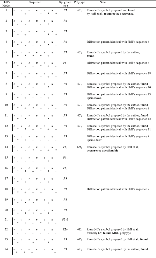
In the study of Hall et al. (Reference Hall, Guggenheim, Moore and Bailey1976) the structure models of the group D six-layer polytypes of serpentine minerals, valid also for cronstedtite, were derived and discussed. Those authors referred to 24 possible sequences of layers (Table 2). In order to identify polytypes actually found in crystals studied, theoretical intensities of characteristic reflections of polytypes corresponding to all of Hall’s sequences were calculated with the aid of the program DIFK (Smrčok & Weiss, Reference Smrčok and Weiss1993). The intensities of [
$$\overline{1}$$
 1l]* reflections in range –20 < l < 20 rescaled to arbitrary units of reasonable size are listed in Table 3. The calculations reveal that four pairs of sequences 4 + 6, 7 + 18, 8 + 10, 11 + 12 produce exactly identical diffraction patterns. In addition, the pattern of Hall’s sequence 9 is an upside-down version of that of 13. Corresponding identification diagrams were also constructed and are presented in Fig. 14. Redundant diagrams of all five above-mentioned equivalent pairs are omitted, so that the total number of diagrams in the picture is 19. These diagrams were used for identification of subfamily D six-layer polytypes in the current study and might also serve for identification of such polytypes in future studies. Some of the diagrams are identical to those already presented in Fig. 2 (albeit using different scales). Diagram 22 is identical to II, 23 to VI, 14 to V, and 3 to VII.
Sequences of six-layer polytypes of the subfamily D serpentines derived by Hall et al. (Reference Hall, Guggenheim, Moore and Bailey1976)
 |
Calculated intensities (in arbitrary units) of characteristic reflections a [
$$\overline{1}$$
 1l]* row – one of three equivalent [10l]* / [01l]* / [
$$\overline{1}$$
 1l]* rows in (h0l hex)* / (0kl hex)* / (
$$\overline{h}$$
 hl hex) RS sections (i.e. [
$$1\overline{1}$$
 l]* / [11l]* / [02l]* in (h
$$\overline{h}$$
 l ort)*, (hhl ort)*, (0kl ort)* in the orthohexagonal setting) of all Hall’s sequences of six-layer polytypes of serpentines of the subfamily D. Intensities >35 are boldfaced

Identification diagrams of six-layer polytypes corresponding to 24 Hall’s sequences of the subfamily D. On the left side, the [00l]* row is added as a common scale. The serial numbers of sequences (or of pairs of sequences producing the same diffraction patterns) and Ramsdell’s symbols of polytypes identified are below

Structure models of commonly occurring polytypes 2H 1 and 2H 2 from the subfamily D

The (h0l hex)* RS sections of trigonal six-layer polytypes actually found in the occurrence. Reciprocal lattice vectors and selected indices of stronger reflections in rows are indicated. a The 6T 1 polytype, corresponding to the Hall’s sequence 1 (sample IV-75B). b The 6T 3 polytype, sequence 5 (sample IV-8B2). c The 6T 4 polytype, sequence 11 or 12 (sample IV-8M21). d The 6T 5 polytype, sequence 8 or 10 (sample IV-146)

Structure models of six-layer polytypes. a Polytype 6T 1, corresponding to Hall’s sequence 1. b Polytype 6T 3, corresponding to the Hall’s sequence 5. c, d Two possible structure models of the polytype 6T 4, corresponding to sequences 11 and 12, respectively, producing identical diffraction patterns. The shift arrows and vectors <*>, <+>, <-> are omitted in models of six-layer polytypes because of multiple overlaps

Further structure models of six-layer polytypes. a, b Two possible models of the polytype 6T 5, corresponding to sequences 8 and 10, respectively, producing identical diffraction patterns

Further (h0l hex)* RS sections of six-layer polytypes. a The 6R 1 polytype, sequence 22 (sample IV-8T). b The 6R 2 polytype, sequence 23 (sample IV-98P). c The 6T 6 polytype, sequence 24 (sample IV-86)

Structure models of six-layer polytypes. a, b The rhombohedral polytypes 6R 1 and 6R 2, sequences 22 and 23, respectively. c Sequence 24 is, according to the model, not rhombohedral, but trigonal, and the proposed Ramsdell’s symbol is 6T 6. d The structure model of the sequence 14 corresponding to the polytype 6H 2

a The (h0l hex)* RS sections of the 6H 2 polytype, sequence 14. The same diffraction pattern can be obtained from the 6R 2 polytype twinned with rotation by 180° about chex as a twin operation, however (sample IV-8M1). b The RS sections produced by the twinned 6R 2 polytype with remarkably unequal amounts of twin components (sample IV-168M1)

Cleaving scheme of the allotwinned crystal of six polytypes. In the image taken by the diffractometer camera, the form of the crystal and the approximate positions of later cuts are outlined. The polytypes identified in respective fragments are indicated (sample IV-8)

Examples of RS sections of strongly textured polycrystalline samples. a The apparent superposition of (hhl hex)* and (h0l hex)* sections of the well ordered 2H 2 polytype of subfamily D (sample CP-11). b–d Examples of diffraction rings at the level of (hk2hex)* RS section of several specimens varying from coarse-grained to almost smooth (samples CP-11, CP-2, CP-8, respectively)

a The BSE image of the polycrystalline aggregate with fiber texture. Crystals are elongated about chex, and are parallel to the section in clusters above and below the center of the image. In the central cluster, the orientation of crystals is somewhat inclined, so that they are cut obliquely. Borders of particular crystals are recognizable (sample CP-2). b For comparison, the BSE image of the common allotwinned single crystal of polytypes 2H 1+6T 1 of subfamily D (sample IV-125). Note the same degree of grady throughout the surfaces of both specimens due to the homogeneity of chemical composition

Range of calculated x-values for individual cronstedtite polytypes (CP = central part of the sample)

Graph of calculated Mn vs. Mg contents (a.p.f.u.) for cronstedtite from the central part of the sample and veins

Graph of calculated x-values vs. Mn contents (a.p.f.u.) for cronstedtite from the central part of the sample and veins

Graph of calculated x-values vs. Cl contents (a.p.f.u.) for cronstedtite from the central part of the sample and veins

In order to check the symmetry of the polytypes, structure models in representative figures were constructed for all 24 of Hall’s sequences. The complete list is available in the Supplementary Material as the file Sequences.pdf or can be obtained from the first author (JH) upon request.
All six-layer polytypes of group D of cronstedtite from the Ouedi Beht occurrence represent ideal non-deformedhexagonal primitive (hP) or rhombohedral (hR) lattices.Unit-cell parameters of all of them are identical, a = 5.49, c = 42.80 Å. Deviations from hexagonal unit-cell parameters calculated by the CrysAlis software were of the same order as standard uncertainties and neither lattice deformation due to symmetry reduction nor splitting of reflections due to twinning was observed. The constrained cells are thus referred to in Table 1. All (h0l hex)* / (0kl hex)* / (
$$\overline{h}$$
 hl hex)* RS sections of the same crystals have reflections at the same positions, so only one is always presented in Figs 16, 19, 21. The relations between polytypes in allotwins are simple, the ahex vectors are always identical, and the chex of six-layer polytypes correspond to 3chex of 2H 1, 2H 2.
Four trigonal non-MDO six-layer polytypes were separated mechanically from allotwins and their RS sections are presented in Fig. 16. Their structure models in symbolic figures are shown in Figs 17 and 18. Their space group type is P3. First of all, the 6T 1 polytype (Hall’s sequence 1) was confirmed. Its stacking sequence is derived by repeating the sequence of the 2H 2 polytype twice, plus adding one sequence of the 2H 1 polytype (cf. Table 2 and Fig. 17a). The [10l]* and [
$$\overline{1}$$
 0l]* rows in the RS section are characterized by l = 3n reflections which are significantly stronger than others in the same rows (Fig. 16a). This structure model was reported by Hall et al. (Reference Hall, Guggenheim, Moore and Bailey1976) for the Unst-type six-layer serpentine (from Unst, in the Shetland Islands, UK). The present study thus gives precise evidence of this structure in cronstedtite.
For the following three polytypes, the first author (JH) proposes symbols 6T 3, 6T 4, and 6T 5. The 6T 2 symbol was proposed previously by JH for another six-layer polytype of the subfamily A, discovered some time ago (Hybler, Reference Hybler2016; Hybler et al., Reference Hybler, Sejkora and Venclík2016). This polytype was mentioned above as a component of allotwins of subfamily A.
The proposed 6T 3 polytype corresponds to sequence 5. Its structure model is shown in Fig. 17b, and the related RS section in Fig. 16b. Here, the [10l]* and [
$$\overline{1}$$
 0l]* rows are characterized by l = 6n reflections which are significantly stronger than others. This arrangement is obeyed also for second-order characteristic reflections [20l]* and [
$$\overline{2}$$
 0l]*. The polytype is characterized by two repetitions of the 2H 1 sequence followed by one 2H 2 sequence. Among all of the six-layer trigonal polytypes, this was the one found most frequently in the sample studied.
The proposed 6T 4 polytype corresponds to sequences 11 or 12, structure models in Fig. 17c,d. The [10l]* and [
$$\overline{1}$$
 0l]* rows in the RS section (Fig. 16c) are characterized by reflections l = 6n–1 and l = 6n+1, respectively, stronger than the others. Finally, the proposed 6T 5 polytype is produced by the sequence 8 or 10; structure models are shown in Fig. 18a,b. The RS section is shown in Fig. 16d. Here, the reflections l = 3n–1 and l = 3n+1 in rows [10l]* and [
$$\overline{1}$$
 0l]*, respectively, are significantly stronger.
Despite the author’s best efforts, mechanical separation of polytypes by cleaving is not always perfect. In Fig. 16b which represents the RS section of the polytype 6T 3 (Hall’s sequence 5), a more detailed check of the RS section revealed that all the l ≠ 6n reflections are not equally weak, as in the identification diagram. The l = 6n+1 and l = 6n–1 reflections in [10l]* and [
$$\overline{1}$$
 0l]* rows, respectively, are somewhat stronger than the other l ≠ 6n reflections. The crystal studied is in fact the allotwin of 6T 3 with a small amount of the 6T 4 polytype (cf. Fig. 16c).
The RS sections of six-layer polytypes corresponding to Hall’s sequences 22, 23, and 24 are represented in Fig. 19. Structure models are shown in Fig. 20a–c. These polytypes were also separated by cleaving of allotwinned crystals. The 6R 1 polytype (sequence 22, structure model Fig. 20a, RS section Fig. 19a, space group type R3c) was formerly referred to as 6R (Bailey, Reference Bailey1969), but the existence of another rhombohedral polytype required addition of a distinctive index as proposed by Wicks and Whittaker (Reference Wicks and Whittaker1975) and Hall et al. (Reference Hall, Guggenheim, Moore and Bailey1976). An example of this structure already found in amesite from Antarctica was mentioned by Hall and Bailey (Reference Hall and Bailey1976). The period of the [10l]* and [
$$\overline{1}$$
 0l]* rows are the same as the [00l]* row, but shifted by 1/3 or –1/3, so that they also correspond to the diagram II in Fig. 2. The 6R 1 is the only MDO polytype among six-layer polytypes of group D. It is characterized by a monotonous repetition of one stacking vector (<–>). The structure model in Fig. 20a and the sequence in Table 2 represent the polytype in the reverse setting. For the obverse setting, the sequence reads:

and the structure model is represented by the mirror image of Fig. 20a. This structure corresponds also to model 16 proposed by Steadman (Reference Steadman1964).
Another rhombohedral polytype 6R 2(sequence 23, structure model in the reverse setting in Fig. 20b, space group type R3) was identified also. The period of [10l]* and [
$$\overline{1}$$
 0l]* rows in the RS section (Fig. 19b) is half of the [10l]* row, shifted by 1/6 or –1/6 with respect to its periodicity, corresponding also to diagram VI in Fig. 2. Figure 20b and the sequence in Table 2 represent the reverse setting. For the obverse setting, the sequence reads:

and the structure model is represented by the mirror image of Fig. 20b. This structure also corresponds to models 12 and 13 of Steadman (Reference Steadman1964). In this polytype, pairs of rotated, but non-shifted layers (in fact 2H 1 sequences) are, as a whole, shifted monotonously by <–> or <+>. This structure model was mentioned by Steadman and Nuttall (Reference Steadman and Nuttall1962) for amesite from Saranovskaya (now Perm region, Russia). The crystal used by those authors was triclinically distorted, however, and split reflections were observed due to the twinning. The 6R 1 and 6R 2 polytypes of lizardite were identified by SAED in serpentine from Woods Chrome Mine, Lancaster County, Pennsylvania, USA by Banfield et al. (Reference Banfield, Bailey, Barker and Smith II1995). The 6R 2 polytype, together with the 2H 2 polytype here, forms segments of polygonal serpentine.
For sequence 24, Hall et al. (Reference Hall, Guggenheim, Moore and Bailey1976) also proposed a rhombohedral polytype space group type R3. The structure model, however, shown in Fig. 20c, obviously does not obey the rhombohedral centering. The possible space group type is thus P3. This polytype was also found in several cleaved fragments and its RS section is shown in Fig. 19c. The proposed Ramsdell’s symbol is 6T 6.
Several cleaved fragments produced RS sections with [10l]* and [
$$\overline{1}$$
 0l]* rows corresponding to Hall’s sequence 14 (i.e. diagram V in Fig. 2). The structure model (Fig. 20d) obeys the hexagonal symmetry, the space group type is P63. For sequence 14, Wicks and Whittaker (Reference Wicks and Whittaker1975) proposed symbol 6H 2, because symbol 6H 1 is still reserved for a yet to be discovered MDO polytype of the subfamily B (cf. Fig. 2). The same diffraction pattern can be produced by the twin reticular merohedry of the rhombohedral polytype 6R 2, with rotation by 180° about chex as the twin operation. This kind of twinning occurs in all polytypes of the A group, where it affects the subset of subfamily reflections of all polytypes. In the D group, it affects the characteristic polytype reflections of rhombohedral polytypes due to the existence of twin individuals in obverse and reverse settings. In the reciprocal space, the [10l]* and [
$$\overline{1}$$
 0l]* rows are superimposed on their upside-down (or mirror) images. In the RS section (Fig. 21a) [10l]* and [
$$\overline{1}$$
 0l]* rows correspond well to diagram 14. It can represent either the polytype 6H 2 or twinned polytype 6R 2 with almost equal amounts of both twin components. Twinned 6R 2, with remarkably unequal proportions of components, are represented in Fig. 21b. The probable interpretation of Fig. 21a is thus the RS section of the twinned 6R 2 polytype rather than of 6H 2.
For illustration, one of complicated allotwins (labelled as IV_8, from the internal vein), cleaved subsequently into smaller fragments, is presented in Fig. 22. On the image of the original crystal recorded by the diffractometer camera the approximate positions of subsequent cuts are outlined. The RS section produced by the whole crystal is shown in Fig. 13d. At the beginning, the crystal was cut tentatively into four fragments, denoted as IV-8P (Peak), IV-8T (Top), IV-8M (Middle), and IV-8B (Bottom). However, the IV-8M and IV-8B fragments needed further cleaving into IV-8M1, IV-8M2, IV-8B1, IV-8B2 parts, and IV-8M2 was finally cleaved into IV-8M21 and IV-8M22. The polytypes present are indicated together with respective Hall’s sequences. The total number of polytypes identified in the crystal reached six: 2H 1, 2H 2, 6R 1, 6T 3, 6T 4, and 6H 2 or twinned 6R 2 (cf. also Table 1).
Textured Aggregates of Subfamily D
Several specimens separated from the central part of the sample appeared to be polycrystalline aggregates with a strong fiber texture – (001) preferred orientation and azimuthally misoriented (100) and (010) directions of domains or crystallites. The (
$$2h\overline{h}$$
 l hex)*/ (hhl hex)*/ (
$$\overline{h}$$
 2hl hex)* and (h0l hex)*/ (0kl hex)* / (
$$\overline{h}$$
 hl hex)* RS sections indicating that the subfamily D and 2H 2 polytype were superimposed (Fig. 23a). In order to examine further these peculiar kinds of intergrowths, the series of RS sections (hk0hex)*, (hk1hex)*, (hk2hex)*, (hk2hex)*, (hk4hex)*, etc., perpendicular to chex was generated. In these sections, concentric rings around chex were recorded instead of discrete reflections. The apparent reflections visible in (
$$2h\overline{h}$$
 l hex)*/ (hhl hex)*/ (
$$\overline{h}$$
 2hl hex)* and (h0l hex)*/ (0kl hex)* / (
$$\overline{h}$$
 hl hex)* RS sections were in fact intersections of named planes with these rings rather than discrete points. The nature of rings varied from sample to sample, from coarse-grained to quite smooth (Fig. 23b–d). In addition to [00l]* row with discrete maxima, some reflections and/or denser maxima on rings were usually present in the reciprocal space, however, so that indexing of diffraction patterns and generation of RS sections became possible. For few crystals, however, the indexing procedure failed, possibly due to rings which were ‘too perfect’ in the reciprocal space. The BSE photograph of one of these specimens (CP-2) revealed the existence of domains elongated in the c direction, probably misoriented azimuthally (Fig. 24a). For comparison, a BSE image of an ordinary single crystal of the subfamily D has been added to Fig. 24b.
Chemical Composition
The full data set of analyses is given in Table S2 (Supplementary Materials). The BSE imaging suggests the compositional homogeneity of all studied fragments of cronstedtite crystals (see Fig. 24). The calculated x-values in the general formula range between 0.62 and 0.81 and for individual polytypes are comparable (Fig. 25). The study of chemical composition (Tables 4, S2) revealed significant systematic differences among crystals from the central part of the sample and from the veins. Cronstedtite from the central part is relatively Mg- (0.19–0.25 a.p.f.u.) and Mn- (0.09–0.10 a.p.f.u.) poor (Figs. 26 and 27) and shows increased contents of Cl in the range 0.013–0.020 a.p.f.u. (Fig. 28). The presence of minor Cl in cronstedtite is already known, e. g. from Pohled (Hybler et al., Reference Hybler, Sejkora and Venclík2016), Chyňava (Hybler & Sejkora, Reference Hybler and Sejkora2017), and (together with S) from Nižná Slaná (Hybler et al., Reference Hybler, Števko and Sejkora2017). On the contrary, cronstedtite from veins contains distinctly more Mg (0.31–0.76 a.p.f.u.) and Mn (0.30–0.47 a.p.f.u.). Certain amounts of Mg and/or Mn partially replacing Fe2+ in octahedra have been reported from some occurrences, e.g. Příbram (Geiger et al., Reference Geiger, Henry, Bailey and Maj1983; Steinmann, Reference Steinmann1821) or Chyňava (Hybler & Sejkora, Reference Hybler and Sejkora2017). Due to the relatively large Mn+Mg contents, the cronstedtite studied represents a transitional structure to guidottiite (Wahle et al., Reference Wahle, Bujnowski, Guggenheim and Kogure2010). Cl contents determined from cronstedtite in veins are irregular and do not exceed 0.009 a.p.f.u. (Fig. 28). Detectable contents of other elements in both types of cronstedtite occurrence were recorded only exceptionally (Al ≤ 0.014 a.p.f.u., S ≤ 0.004 a.p.f.u.).
Variations in chemical composition of the studied polytypes of cronstedtite from Ouedi Beht. Contents of ions per formula unit are given. n– number of spot analyses

Conclusions
The present study contains many interesting new findings. First of all, the study reports a new occurrence of cronstedtite in a skarn deposit. The geological setting and paragenesis are described.
The Ouedi Beht sample is unusually rich in polytypes in numbers not comparable with any other sample studied before. Single-crystal X-ray diffraction with the aid of diffractometers equipped with area detectors led to the discovery of rare polytypes, mostly as part of more or less complicated allotwins. Nevertheless, note that these crystals are very rare in the sample studied. The majority of specimens tested contained common polytypes 2H 1 and 2H 2. The rare polytypes are present in crystals selected from veins (mainly from internal vein – IV), not from the central part. The experimental work thus required a lot of routine checking of numerous specimens and selecting only a limited number of candidates for further studies. Modern diffractometers have allowed for all of this work to be done in a reasonable amount of time.
RS sections of polytypes, twins, and allotwins presented in the study show clear evidence of their existence. They also clarify relations between individuals of twins and allotwins, mainly of monoclinic polytypes.
Several six-layer non-MDO polytypes, not found previously, were discovered – 6T 3, 6T 4, 6T 5, and 6T 6. In addition, rare six-layer polytypes 6T 1, 6R 1, 6R 2, and maybe 6H 2, known from other serpentine minerals, were also found. Stacking sequences of all of the polytypes were predicted by Hall et al. (Reference Hall, Guggenheim, Moore and Bailey1976). For their correct determination, the theoretical diffraction patterns were calculated and identification diagrams constructed. The RS sections of isolated polytypes matched the diagrams perfectly. They might serve for identification of further polytypes of this kind in the future.
Simple mechanical cleaving of complicated allotwins into smaller fragments proved to be a feasible way to isolate polytypes for determination by single-crystal X-ray diffraction. Without this practice, interpreting the RS sections of complicated allotwins, mainly of six-layer polytypes of the subfamily D (cf. Fig. 13d), could be impossible. The method has certain limits, however. The cuts need to be close enough to actual borders of domains of polytypes in the crystals. This needs a bit of luck. The cutting must be repeated in some cases. The manipulation of fragments under the microscope needs also much care in order to preserve the information about the succession of cleaved parts in the original crystal. The polytype in a fragment should be ‘as separated as possible,’ but sometimes some residuals of other polytypes might be recognized in diffraction patterns, as in Fig. 16b. This should always be considered if the diffraction pattern does not fit the identification diagram perfectly. Mechanical cleaving was used by Hybler et al. (Reference Hybler, Števko and Sejkora2017) for one allotwinned crystal from Chyňava.
The scheme in Fig. 22 illustrates the changing stacking sequences during crystal growth and represents an extreme example of a very complicated allotwin. If the polytypes in allotwins are too intimately inter-grown and/or the polytypes alternated frequently during the growth, mechanical separation is usually not possible. In the Ouedi Beht sample, the A-group polytypes could not be separated mechanically from allotwins. The only exceptions were successful separations of the 2M 1 polytype from the peak parts of a few allotwinned crystals.
The single-crystal diffraction of allotwins allows identification of polytypes in amounts above the detection threshold of the method. Some minute amounts of other polytype(s) might be present but cannot be detected. More detailed studies might be performed in the future with the aid of electron diffraction tomography (EDT) and/or high-resolution electron microscopy (HRTEM).
The discovery of several aggregates with fiber texture from the central part is an interesting novelty. The chemical analyses revealed certain differences between relatively Mn+Mg-rich crystals from veins and Mn+Mg-poor crystals from the central part of the sample, emphasizing the different character of both kinds of crystals. In fact, crystals from veins represent a transitional structure to guidottiite. Apart from this difference, no significant correlations of the polytype and composition were observed. This is in accord with findings of cronstedtite from other localities. Cl and S detected in trace amounts are common substituents for OH in cronstedtite.
Supplementary Information
The online version contains supplementary material available at https://doi.org/10.1007/s42860-021-00157-2.
ACKNOWLEDGMENTS
The authors thank Jordi Fabre and Tomasz Praszkier for valuable information about the mineral find and locality. JH thanks Slavomil Ďurovič, senior researcher at the Institute of Inorganic Chemistry, Slovak Academy of Sciences, Bratislava, for many valuable discussions. The fiber textures were discussed with Milan Rieder. Numerous comments by the Editor-in-Chief, Associate Editor Eric Ferrage, and three anonymous reviewers helped to improve the manuscript substantially. The research was supported by project 18-10504S of the Czech Science Foundation, and by project CZ.02.1.01/0.0/0.0/16_019/0000760 Solid 21 under the Ministry of Education, Youth and Sports to JH, and due to institutional funding of the National Museum as a research organization 00023272 under project DKRVO 2019-2023/1.II.c to ZD and JS.
Funding
Funding sources are as stated in the Acknowledgments.
Compliance with Ethical Statements
Conflict of Interest
The authors declare that they have no conflict of interest.