1 Introduction
Ten years ago, Yves Couder and Emmanuel Fort discovered that a millimetric drop placed on a vibrating fluid bath may interact with its own wave field in such a way as to walk steadily across the surface (Couder et al. Reference Couder, Protière, Fort and Boudaoud2005; Protière, Boudaoud & Couder Reference Protière, Boudaoud and Couder2006). These walking droplets, henceforth ‘walkers’, are composed of both droplet and extended wave, and exhibit several features previously thought to be exclusive to the microscopic, quantum realm (see reviews by Bush Reference Bush2015a ,Reference Bush b ). Integrated experimental and theoretical work has rationalized the manner in which chaotic pilot-wave dynamics may give rise to quantum-like statistical behaviour in unbounded geometries, for example in orbital dynamics (Fort et al. Reference Fort, Eddi, Boudaoud, Moukhtar and Couder2010; Harris & Bush Reference Harris and Bush2014; Labousse et al. Reference Labousse, Perrard, Couder and Fort2014, Reference Labousse, Oza, Perrard and Bush2016; Oza et al. Reference Oza, Harris, Rosales and Bush2014; Perrard et al. Reference Perrard, Labousse, Fort and Couder2014a ,Reference Perrard, Labousse, Miskin, Fort and Couder b ). The interaction of walkers with boundaries, as arises in a number of key quantum analogue systems (Couder & Fort Reference Couder and Fort2006; Eddi et al. Reference Eddi, Fort, Moisy and Couder2009; Harris et al. Reference Harris, Moukhtar, Fort, Couder and Bush2013; Gilet Reference Gilet2014, Reference Gilet2016), remains relatively poorly understood.
In their experimental investigation of walkers tunnelling across submerged barriers, Eddi et al. (Reference Eddi, Fort, Moisy and Couder2009) noted the predominance of a single reflection angle of approximately
 $60^{\circ }$
(measured with respect to the normal) when the walker bounced off the walls of a square cavity. Indeed, this reflection behaviour was exploited in the development of their experimental arrangement. Couder & Fort (Reference Couder and Fort2006) showed that walkers exhibit single-particle diffraction and interference when they pass through single- or double-slit geometries. Recently, Andersen et al. (Reference Andersen, Madsen, Reichelt, Ahl, Lautrup, Ellegaard, Levinsen and Bohr2015) and Batelaan et al. (Reference Batelaan, Jones, Huang and Bach2016) revisited these experiments and found results at odds with those of Couder & Fort (Reference Couder and Fort2006). Harris (Reference Harris2015) examined the diffraction of walkers through a slit, and found the behaviour to be dominated by wall effects. Specifically, there was a preferred diffraction angle of approximately
 $60^{\circ }$
, comparable to the angle of reflection of a walker from a planar boundary.
A prerequisite for the theoretical rationale of the behaviour in the diffraction and interference experiments would thus seem to be the understanding of the interaction of walkers with relatively simple boundary geometries. We here examine experimentally and theoretically the interaction of walking droplets with a planar submerged barrier. Specifically, in § 2, we characterize the reflection laws of walking droplets experimentally, then in § 3 capture the observed behaviour with simulations based on a recently developed theoretical model (Faria Reference Faria2016). The rationale for the non-specular reflection is provided in § 4 on the basis of existing reduced theoretical models of the walker dynamics (Bush, Oza & Molácek Reference Bush, Oza and Molácek2014; Labousse & Perrard Reference Labousse and Perrard2014).
2 Experiments
The fluid bath is composed of silicone oil with viscosity
 $\unicode[STIX]{x1D708}=20.9~\text{cSt}$
, density
 $\unicode[STIX]{x1D70C}=950~\text{kg}~\text{m}^{-3}$
and surface tension
 $\unicode[STIX]{x1D70E}=20.6~\text{mN}~\text{m}^{-1}$
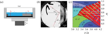
. A schematic of the set-up is presented in figure 1. The bath is circular with diameter 15.8 cm, depth
 $h_{0}=6.09\pm 0.03~\text{mm}$
and is surrounded by a shallow border of width 12.7 mm and depth 1.3 mm that acts as a wave damper, thus minimizing the interaction of the walker with the outer boundary. A stainless steel barrier (visible on the right of figure 1
b) is bolted to an aluminium base plate and serves as the reflecting planar boundary. On the barrier, the fluid depth is reduced to
 $h_{1}=0.42\pm 0.03~\text{mm}$
, which is too shallow to support a walking drop. This depth
 $h_{1}$
was chosen to correspond most closely to that used by Harris (Reference Harris2015) for the single-slit diffraction experiments. The barrier is 30 mm wide so that the droplets cannot tunnel across it (Eddi et al.
Reference Eddi, Fort, Moisy and Couder2009) and waves do not propagate beyond it.
(a) Experimental set-up (not to scale). In the vicinity of the reflecting barrier, the fluid depth is reduced from
 $h_{0}=6.09\pm 0.03~\text{mm}$
to
 $h_{1}=0.42\pm 0.03~\text{mm}$
. (b) Typical trajectory (in red) of a walking droplet reflecting off the planar boundary. The droplet is launched from a submerged V-shaped launcher (in black) towards the reflecting barrier (in grey). The local angle of incidence
 $\unicode[STIX]{x1D703}_{i}$
and reflection
 $\unicode[STIX]{x1D703}_{r}$
at the two black points are indicated. (c) Parameter regimes of bouncing and walking drops indicating the dependence of the bouncing state
 $(m,n)$
on the dimensionless acceleration
 $\unicode[STIX]{x1D6FE}/g$
and the vibration number
 $V_{i}=\unicode[STIX]{x1D714}/\sqrt{\unicode[STIX]{x1D70E}/\unicode[STIX]{x1D70C}R^{3}}$
, where
 $R$
is the drop radius (Molacek & Bush Reference Molacek and Bush2013b
). In the
 $(m,n)^{k}$
mode, the drop bounces
 $n$
times in
 $m$
driving periods.
 $(2,1)^{1}$
and
 $(2,1)^{2}$
denote resonant walkers with a different mean mechanical energy. The white segments indicate the parameter regimes explored in our study. White and blue circles correspond to the droplets used in figure 3(c), while the yellow circle corresponds to that used for the visualization of the wave field in figure 6.

The bath is driven at the frequency
 $f_{0}=80$
Hz by an electromagnetic shaker with acceleration
 $\unicode[STIX]{x1D6E4}(t)=\unicode[STIX]{x1D6FE}\cos (\unicode[STIX]{x1D714}t)$
, where
 $\unicode[STIX]{x1D714}=2\unicode[STIX]{x03C0}f_{0}$
. The drive shaft is guided by a linear air bearing that ensures a spatially uniform vertical vibration to within 0.1 %. The forcing is controlled by a closed-loop feedback that ensures a constant acceleration amplitude to within
 $\pm 0.002~\text{g}$
(Harris & Bush Reference Harris and Bush2015), and monitored by two accelerometers placed symmetrically with respect to the centre of the bath. For
 $\unicode[STIX]{x1D6FE}\geqslant \unicode[STIX]{x1D6FE}_{F}\simeq 4.2~\text{g}$
, the Faraday instability arises on the bath, resulting in standing gravity–capillary waves of wavelength
 $\unicode[STIX]{x1D706}_{F}=4.75~\text{mm}$
and frequency
 $f_{0}/2$
(Faraday Reference Faraday1831). We examine droplets walking below this threshold, so that the dimensionless acceleration, henceforth referred to as the ‘forcing amplitude’,
 $\unicode[STIX]{x1D6FE}/\unicode[STIX]{x1D6FE}_{F}<1$
. The experimental uncertainty in
 $\unicode[STIX]{x1D6FE}/\unicode[STIX]{x1D6FE}_{F}$
is less than 0.2 % and due primarily to the small variation of the Faraday threshold during the course of the experiments, as arises due to the dependence of the fluid viscosity on temperature. The forcing amplitude uniquely defines the memory parameter
 $M_{e}=T_{d}/[T_{F}(1-\unicode[STIX]{x1D6FE}/\unicode[STIX]{x1D6FE}_{F})]$
, where
 $T_{d}$
is the wave decay time in the absence of vibration and
 $T_{F}=2/f_{0}$
is the period of the Faraday waves (Eddi et al.
Reference Eddi, Sultan, Moukhtar, Fort, Rossi and Couder2011; Molacek & Bush Reference Molacek and Bush2013b
).
 $M_{e}$
gives an estimation of the number of past bounces that contribute to the build-up of the instantaneous guiding wave field. Throughout this paper we will refer alternatively to the forcing amplitude and the memory.
Droplets of the same silicone oil as the bath are generated via the droplet-on-demand generator developed by Harris, Liu & Bush (Reference Harris, Liu and Bush2015), which reduces uncertainty in the drop diameter
 $D$
to
 $\pm 0.01~\text{mm}$
. Droplets are released onto the vibrating bath along a slide painted with a thin layer of silicone oil. The parameter regime of the drops used in this work is highlighted in figure 1(c). We explored the behaviour of walking drops of three different sizes in the resonant
 $(2,1)^{2}$
mode, in the
 $(4,2)$
mode and in the chaotic regime arising at high memory for relatively small drops (Molacek & Bush Reference Molacek and Bush2013b
; Wind-Willassen et al.
Reference Wind-Willassen, Molacek, Harris and Bush2013). The container is sealed with a transparent acrylic lid to isolate the droplet from ambient air currents. Walkers were directed towards the barrier with a V-shaped launcher (see figures 1(b) and 2), above which the fluid depth was reduced to 0.6 mm. At the exit of the launcher, droplets follow a straight path until they start interacting with the reflecting barrier. After the reflection event, they usually follow the outer wall until returning to the launcher, which allowed for repeated measurements in the same experimental conditions. The initial angle of incidence was controlled by shifting the position of the launcher.
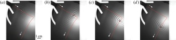
Four snapshots of a walking droplet with its wave field as it is reflected from a submerged barrier (in white). (a)
 $t=1.2~\text{s}$
, (b)
 $t=4.4~\text{s}$
, (c)
 $t=7.1~\text{s}$
, (d)
 $t=9.4~\text{s}$
.

The walker motion was recorded with a CCD camera at 10 frames per second and tracked with an in-house particle-tracking algorithm. Angles were measured locally along the trajectories by considering the tangent line at the point of measurement and the first four neighbours. The angle between this line and the normal to the barrier was defined to be the local angle of incidence
 $\unicode[STIX]{x1D703}_{i}$
or reflection
 $\unicode[STIX]{x1D703}_{r}$
(figure 1
b) along, respectively, the incoming and outgoing portions of the trajectory. In the far field,
 $\unicode[STIX]{x1D703}_{i}$
and
 $\unicode[STIX]{x1D703}_{r}$
asymptote to the initial angle of incidence
 $\unicode[STIX]{x1D6E9}_{i}$
and the final angle of reflection
 $\unicode[STIX]{x1D6E9}_{r}$
, respectively.
 $\unicode[STIX]{x1D6E9}_{i}$
is defined as the average over the first 10 values of
 $\unicode[STIX]{x1D703}_{i}$
at the exit of the launcher, and
 $\unicode[STIX]{x1D6E9}_{r}$
similarly by the average over the last 10 values of
 $\unicode[STIX]{x1D703}_{r}$
.
First, we characterize the dependence of the final reflection angle
 $\unicode[STIX]{x1D6E9}_{r}$
on the initial incident angle
 $\unicode[STIX]{x1D6E9}_{i}$
at relatively low memory. We consider a droplet of diameter
 $D=0.78~\text{mm}$
at two accelerations,
 $\unicode[STIX]{x1D6FE}/\unicode[STIX]{x1D6FE}_{F}=0.850$
and
 $\unicode[STIX]{x1D6FE}/\unicode[STIX]{x1D6FE}_{F}=0.900$
, where it is a resonant
 $(2,1)^{2}$
walker with respective speeds
 $v_{0}=10.6\pm 0.1~\text{mm}~\text{s}^{-1}$
and
 $v_{0}=11.45\pm 0.10~\text{mm}~\text{s}^{-1}$
. For each
 $\unicode[STIX]{x1D6E9}_{i}$
, we repositioned the launcher so that the walker impinges close to the centre of the barrier. We then resealed the container, and recorded at least two trajectories. These trajectories were indistinguishable within the errors of our experimental set-up. At these low memories, the trajectory is uniquely determined by the initial incident angle
 $\unicode[STIX]{x1D6E9}_{i}$
.
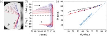
Non-specular reflection of a walking droplet of diameter
 $D=0.78~\text{mm}$
. At
 $\unicode[STIX]{x1D6FE}/\unicode[STIX]{x1D6FE}_{F}=0.900$
, its free speed is
 $v_{0}=11.45\pm 0.10~\text{mm}~\text{s}^{-1}$
. (a) Trajectory colour varies from blue to red as the initial incidence angle
 $\unicode[STIX]{x1D6E9}_{i}$
decreases. The launcher is removed from the image for the sake of clarity. (b) Local measurements of the angle of incidence
 $\unicode[STIX]{x1D703}_{i}$
and reflection
 $\unicode[STIX]{x1D703}_{r}$
as a function of the distance
 $x$
from the barrier. (c) The final reflection angle
 $\unicode[STIX]{x1D6E9}_{r}$
as a function of the initial incidence angle
 $\unicode[STIX]{x1D6E9}_{i}$
for
 $\unicode[STIX]{x1D6FE}/\unicode[STIX]{x1D6FE}_{F}=0.900$
(full circles) and
 $\unicode[STIX]{x1D6FE}/\unicode[STIX]{x1D6FE}_{F}=0.850$
(open circles). These walkers are identified respectively by the blue and white circles in figure 1(c). Experiments are compared to the results from the theoretical model (red and black solid lines, respectively) and the specular reflection law
 $\unicode[STIX]{x1D6E9}_{r}=\unicode[STIX]{x1D6E9}_{i}$
(dashed line).

In figure 3(a) we report one trajectory per
 $\unicode[STIX]{x1D6E9}_{i}$
. The reflection is clearly non-specular:
 $\unicode[STIX]{x1D6E9}_{r}\neq \unicode[STIX]{x1D6E9}_{i}$
. Moreover, we observe that a wide range of
 $\unicode[STIX]{x1D6E9}_{i}$
converges to a narrow band of
 $\unicode[STIX]{x1D6E9}_{r}$
in the vicinity of
 $70^{\circ }$
. This convergence is evident in figure 3(b), where the local angle is reported for each trajectory as a function of the normal distance from the barrier
 $x$
. At the exit of the launcher, the walker proceeds in a rectilinear fashion. As it approaches the barrier, the local angle of incidence
 $\unicode[STIX]{x1D703}_{i}$
generally increases. After the walker reverses direction,
 $\unicode[STIX]{x1D703}_{r}$
changes continuously before approaching its final value
 $\unicode[STIX]{x1D6E9}_{r}$
in the far field, where the walker proceeds again in a rectilinear fashion. The reflection process occurs over a time interval of several seconds, during the course of which the walker interacts with the planar barrier through its wave field. We note that along both the incident and reflected trajectories, the walker curves towards the barrier, except during its relatively abrupt reversal of direction, as arises at a distance from the barrier that depends on
 $\unicode[STIX]{x1D6E9}_{i}$
but is in the range 0.6–
 $2.8\unicode[STIX]{x1D706}_{F}$
. The final reflection angle
 $\unicode[STIX]{x1D6E9}_{r}$
is plotted as a function of the initial incidence angle
 $\unicode[STIX]{x1D6E9}_{i}$
in figure 3(c), where the deviation from specular reflection is again apparent. For
 $\unicode[STIX]{x1D6FE}/\unicode[STIX]{x1D6FE}_{F}=0.900$
, the wide range of initial angles of incidence
 $\unicode[STIX]{x1D6E9}_{i}\in [14^{\circ },76^{\circ }]$
results in a relatively narrow band of final reflection angles
 $\unicode[STIX]{x1D6E9}_{r}\in [64^{\circ },82^{\circ }]$
. For
 $\unicode[STIX]{x1D6FE}/\unicode[STIX]{x1D6FE}_{F}=0.850$
, the wide range of initial angles of incidence
 $\unicode[STIX]{x1D6E9}_{i}\in [14^{\circ },71^{\circ }]$
results in an even narrower band of final reflection angles
 $\unicode[STIX]{x1D6E9}_{r}\in [69^{\circ },81^{\circ }]$
.
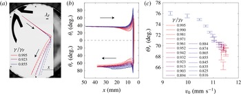
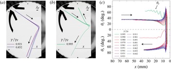
Dependence on memory,
 $\unicode[STIX]{x1D6FE}/\unicode[STIX]{x1D6FE}_{F}$
, of the reflection of a walker of diameter
 $D=0.78~\text{mm}$
for a fixed initial angle of incidence
 $\unicode[STIX]{x1D6E9}_{i}=37.3\pm 0.5^{\circ }$
. The path through parameter space is indicated by the uppermost white line segment in figure 1(c). Colour changes from blue to red as
 $\unicode[STIX]{x1D6FE}/\unicode[STIX]{x1D6FE}_{F}$
increases. (a) Three experimental trajectories (solid lines) compared to computed trajectories (dashed lines). (b) Local measurement of the incidence angle
 $\unicode[STIX]{x1D703}_{i}$
and the reflection angle
 $\unicode[STIX]{x1D703}_{r}$
as a function of the distance from the barrier
 $x$
. (c) Final reflection angle
 $\unicode[STIX]{x1D6E9}_{r}$
as a function of the drop free speed
 $v_{0}$
. The error on the latter is
 $\unicode[STIX]{x0394}v_{0}=0.05~\text{mm}~\text{s}^{-1}$
.

We also investigated the influence of memory on the reflection of droplets of diameter
 $D=0.78$
and
 $0.75~\text{mm}$
with a fixed
 $\unicode[STIX]{x1D6E9}_{i}$
. In figure 4(a) we present trajectories of the drop of diameter
 $D=0.78~\text{mm}$
. Both incident and reflected trajectories vary with memory. In the approach phase, the low-memory walker senses the barrier at a distance
 $x\approx 10~\text{mm}$
from the barrier. The high-memory walker senses the barrier earlier owing to its relatively extended wave field. These features are highlighted in figure 4(b), where the local angle is plotted for each trajectory as a function of the distance from the barrier
 $x$
. We note that the local minimum in the angle of incidence
 $\unicode[STIX]{x1D703}_{i}$
in the vicinity of the barrier decreases as the memory increases. In figure 4(c), the dependence of
 $\unicode[STIX]{x1D6E9}_{r}$
on the drop free speed
 $v$
is reported for the different memories examined. At the highest memories considered, we were at the limit of our experimental configuration: at the edge of the domain, the walker trajectories were still slightly curved. We note here that
 $\unicode[STIX]{x1D6E9}_{r}$
remains constant for
 $\unicode[STIX]{x1D6FE}/\unicode[STIX]{x1D6FE}_{F}$
from 0.894 to 0.981. In this memory range, the speed is nearly constant, indicating that
 $\unicode[STIX]{x1D6E9}_{r}$
is more sensitive to the drop free speed than to memory. The overall spread of the reflected trajectories in this set of experiments is in the range
 $\unicode[STIX]{x1D6E9}_{r}\in [66^{\circ },76^{\circ }]$
, with higher speeds corresponding to lower reflection angles. We conclude that
 $\unicode[STIX]{x1D6E9}_{r}$
decreases monotonically with the drop’s free speed.
Dependence on memory
 $\unicode[STIX]{x1D6FE}/\unicode[STIX]{x1D6FE}_{F}$
of the reflection of a walker of diameter
 $D=0.75~\text{mm}$
for a fixed initial angle of incidence
 $\unicode[STIX]{x1D6E9}_{i}=34.9\pm 0.6^{\circ }$
(indicated by the middle white line segment in figure 1
c). Comparison of experimental (solid line) and theoretical (dashed line) trajectories at (a) two low memories and (b) one very high memory, where an anomalous trajectory is observed in the experiments but not in the model. (c) Local measurement of the angle of incidence
 $\unicode[STIX]{x1D703}_{i}$
and the reflected angle
 $\unicode[STIX]{x1D703}_{r}$
as a function of the distance
 $x$
from the barrier at different memories. The anomalous trajectory presented in (b) is highlighted in green.

In figure 5(a,b), we present trajectories in the same experimental conditions for a smaller droplet, with diameter
 $D=0.75~\text{mm}$
, whose speed at
 $\unicode[STIX]{x1D6FE}/\unicode[STIX]{x1D6FE}_{F}=0.901$
is
 $v_{0}=9.15\pm 0.10~\text{mm}~\text{s}^{-1}$
. The behaviour is very similar to that arising for
 $D=0.78~\text{mm}$
except at high
 $\unicode[STIX]{x1D6FE}/\unicode[STIX]{x1D6FE}_{F}$
, where the reflection angle may decrease dramatically (at
 $\unicode[STIX]{x1D6FE}/\unicode[STIX]{x1D6FE}_{F}=0.990$
) or even take on negative values (at
 $\unicode[STIX]{x1D6FE}/\unicode[STIX]{x1D6FE}_{F}=0.995$
). In the latter case, the droplet executes a loop whose diameter is approximately one Faraday wavelength, before exiting the loop and wobbling towards rectilinear motion (figure 5
b). The loop is presumably due to a transient self-confinement of the walker in its own wave field, as has been discussed elsewhere (Labousse Reference Labousse2014; Oza et al.
Reference Oza, Harris, Rosales and Bush2014; Bush Reference Bush2015b
). In figure 5(c), oscillations at high memory are clearly evident. While this slower walker asymptotes to
 $\unicode[STIX]{x1D6E9}_{r}$
more slowly than its faster counterpart, the band of final reflection angles is clearly narrower. However, it is difficult here to assess reliably the dependence of
 $\unicode[STIX]{x1D6E9}_{r}$
on memory and drop speed as trajectories are still curved at the limit of the experimental set-up. Equivalent experiments with an even smaller drop (
 $D=0.71~\text{mm}$
, lowermost white horizontal line in figure 1(c), for which
 $v_{0}=6.8\pm 0.1~\text{mm}~\text{s}^{-1}$
at
 $\unicode[STIX]{x1D6FE}/\unicode[STIX]{x1D6FE}_{F}=0.900$
) show that reflection angles are confined to an even narrower band and reversed reflection occurs at a lower memory, specifically for
 $\unicode[STIX]{x1D6FE}/\unicode[STIX]{x1D6FE}_{F}=0.981$
. Above this forcing amplitude, for a given
 $\unicode[STIX]{x1D6E9}_{i}$
, different reversed reflection angles can be obtained, suggesting chaotic reflection dynamics. We note that this apparently chaotic dynamics may result from the chaotic vertical dynamics arising for such a drop at high memory: the rightmost edge of the relevant lower white segment in figure 1(c) lies within a chaotic bouncing regime.
We also examined the reflection of the larger droplet (
 $D=0.78~\text{mm}$
) at
 $\unicode[STIX]{x1D6FE}/\unicode[STIX]{x1D6FE}_{F}=0.950$
and
 $\unicode[STIX]{x1D6FE}/\unicode[STIX]{x1D6FE}_{F}=0.990$
. At such high memories, however, it was again impossible to measure the final angle of reflection
 $\unicode[STIX]{x1D6E9}_{r}$
because the drop trajectories were still curved at the limits of the experimental domain. For
 $\unicode[STIX]{x1D6FE}/\unicode[STIX]{x1D6FE}_{F}=0.990$
and
 $\unicode[STIX]{x1D6E9}_{i}\leqslant 30^{\circ }$
,
 $\unicode[STIX]{x1D6E9}_{r}$
decreases dramatically, and at small
 $\unicode[STIX]{x1D6E9}_{i}$
the drop loops around its own wave field in the vicinity of the barrier and executes reversed reflection. Finally, we investigated the reflection behaviour of a slow drop with diameter
 $D=0.71~\text{mm}$
at
 $\unicode[STIX]{x1D6FE}/\unicode[STIX]{x1D6FE}_{F}=0.900$
and
 $\unicode[STIX]{x1D6FE}/\unicode[STIX]{x1D6FE}_{F}=0.850$
. Here again, the trajectories are still slightly curved at the limit of the experimental set-up, so it is not possible to measure
 $\unicode[STIX]{x1D6E9}_{r}$
. However, we could ascertain that the non-specularity is enhanced: larger values of
 $\unicode[STIX]{x1D6E9}_{r}$
are obtained and lie in a relatively narrow range.
We also investigated the influence of the fluid depth
 $h_{1}$
above the barrier by exploring the behaviour at
 $h_{1}=0.04\pm 0.03~\text{mm}$
and
 $h_{1}=0.81\pm 0.03~\text{mm}$
. Reflection maintains the feature of non-specularity with
 $\unicode[STIX]{x1D6E9}_{r}\approx 70^{\circ }$
. A slight decrease of
 $\unicode[STIX]{x1D6E9}_{r}$
with the drop free speed was apparent, as was the case when
 $h_{1}=0.42~\text{mm}$
.
3 Theoretical modelling
Recently, a reduced model that captures many features observed in experiments has been developed by Faria (Reference Faria2016). Its key feature is that it incorporates the dependence of wave speed on fluid depth in a simple way, and so enables the treatment of walker–boundary interactions. This model builds upon that of Milewski et al. (Reference Milewski, Galeano-Rios, Nachbin and Bush2015) by making the simplifying assumption that the waves are monochromatic; therefore, only waves with Faraday frequency need be considered.
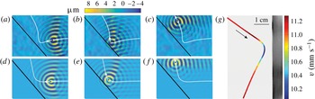
Experimental (a–c) and theoretical (d–f) wave fields as the walker reflects from a planar barrier. Drop diameter
 $D=0.76~\text{mm}$
and free speed
 $v_{0}=11.2~\text{mm}~\text{s}^{-1}$
, height above the barrier
 $h_{1}=0.3~\text{mm}$
and in the deep region
 $h_{0}=10~\text{mm}$
, forcing amplitude
 $\unicode[STIX]{x1D6FE}/\unicode[STIX]{x1D6FE}_{F}=0.979$
(yellow circle in figure 1
c). (g) Speed variation in the vicinity of the barrier of a drop with
 $D=0.78$
mm at
 $\unicode[STIX]{x1D6FE}/\unicode[STIX]{x1D6FE}_{F}=0.903$
with
 $h_{1}=0.42\pm 0.03~\text{mm}$
(blue circle in figure 1
c). Surface Schlieren images (a–c) are taken with the bath at its maximal vertical displacement (courtesy of P.-T. Brun and A. Damiano).

For completeness, we recall the governing equations of Milewski et al. (Reference Milewski, Galeano-Rios, Nachbin and Bush2015) which, when extended to a bath of finite depth, are given by:
 $$\begin{eqnarray}\displaystyle & \displaystyle \unicode[STIX]{x0394}\unicode[STIX]{x1D719}=0,\quad \text{for }-h(\boldsymbol{x})\leqslant z\leqslant 0, & \displaystyle\end{eqnarray}$$
 $$\begin{eqnarray}\displaystyle & \displaystyle \unicode[STIX]{x1D735}\unicode[STIX]{x1D719}\boldsymbol{\cdot }\boldsymbol{n}=0,\quad \text{for }z=-h(\boldsymbol{x}), & \displaystyle\end{eqnarray}$$
 $$\begin{eqnarray}\displaystyle & \displaystyle \unicode[STIX]{x1D719}_{t}=-g(t)\unicode[STIX]{x1D702}+2\unicode[STIX]{x1D708}^{\ast }\unicode[STIX]{x1D6FB}_{\bot }^{2}\unicode[STIX]{x1D719}+\frac{\unicode[STIX]{x1D70E}}{\unicode[STIX]{x1D70C}}\unicode[STIX]{x1D6FB}_{\bot }^{2}\unicode[STIX]{x1D702}-\frac{1}{\unicode[STIX]{x1D70C}}P_{D}(\boldsymbol{x}-\boldsymbol{x}_{p}(t),t),\quad \text{for }z=0, & \displaystyle\end{eqnarray}$$
 $$\begin{eqnarray}\displaystyle & \displaystyle \unicode[STIX]{x1D702}_{t}=\unicode[STIX]{x1D719}_{z}+2\unicode[STIX]{x1D708}^{\ast }\unicode[STIX]{x1D6FB}_{\bot }^{2}\unicode[STIX]{x1D702},\quad \text{for }z=0, & \displaystyle\end{eqnarray}$$
where
 $\unicode[STIX]{x1D719}$
and
 $\unicode[STIX]{x1D702}$
denote the velocity potential and the free-surface displacement, respectively.
 $g(t)=g_{0}(1+\unicode[STIX]{x1D6FE}/g_{0}\cos \unicode[STIX]{x1D714}t)$
is the gravitational acceleration in the bath’s frame of reference,
 $P_{D}$
denotes the pressure exerted by the drop,
 $\boldsymbol{x}_{p}$
denotes the drop’s horizontal position,
 $h(\boldsymbol{x})$
denotes the bottom topography,
 $\unicode[STIX]{x1D708}^{\ast }$
is the effective viscosity and
 $\boldsymbol{n}$
is the unit vector normal to the bottom surface.
 $\unicode[STIX]{x1D735}_{\bot }=(\unicode[STIX]{x2202}_{x},\unicode[STIX]{x2202}_{y})$
denotes the horizontal gradient. The key modification made by Faria (Reference Faria2016) is replacing
 $\unicode[STIX]{x1D719}_{z}$
in (3.4) by
 $-\unicode[STIX]{x1D735}_{\bot }\boldsymbol{\cdot }(\bar{h}\unicode[STIX]{x1D735}_{\bot }\unicode[STIX]{x1D719})$
, where
 $\bar{h}$
is an effective depth chosen to model correctly waves with the Faraday frequency. Over regions of constant depth,
 ${\mathcal{F}}[\unicode[STIX]{x1D719}_{z}(\boldsymbol{x},0,t)]=k\tanh (kh){\mathcal{F}}[\unicode[STIX]{x1D719}(\boldsymbol{x},0,t)]$
, where
 ${\mathcal{F}}$
denotes the Fourier transform in (
 $x,y$
). Consequently, in order for the approximation of Faria (Reference Faria2016) to correctly model the wavenumber
 $k_{F}$
over a depth
 $h$
, the effective depth
 $\bar{h}$
must be
 $$\begin{eqnarray}\bar{h}=\frac{\tanh k_{F}h}{k_{F}}.\end{eqnarray}$$
In the reflection experiments, we have
 $$\begin{eqnarray}h=\left\{\begin{array}{@{}l@{}}h_{0}\quad \text{for }x<0,\quad \\ h_{1}\quad \text{for }x>0.\quad \end{array}\right.\end{eqnarray}$$
The effective depth is then given by
 $$\begin{eqnarray}\bar{h}=\left\{\begin{array}{@{}l@{}}\tanh (k_{F_{0}}h_{0})/k_{F_{0}}\quad \text{for }x<0,\quad \\ \tanh (k_{F_{1}}h_{1})/k_{F_{1}}\quad \text{for }x>0,\quad \end{array}\right.\end{eqnarray}$$
where
 $k_{F_{0}}$
and
 $k_{F_{1}}$
denote the Faraday wavenumber in the deep and shallow regions, respectively. The phase speed of surface waves in the two regions of the bath of depth
 $h_{0}$
and
 $h_{1}$
is then recovered.
The horizontal motion of the walker is governed by Molacek & Bush (Reference Molacek and Bush2013b )
 $$\begin{eqnarray}m\frac{\text{d}^{2}\boldsymbol{x}_{p}}{\text{d}t^{2}}+\left(c_{4}\sqrt{\frac{\unicode[STIX]{x1D70C}R}{\unicode[STIX]{x1D70E}}}F(t)+6\unicode[STIX]{x03C0}R\unicode[STIX]{x1D707}_{air}\right)\frac{\text{d}\boldsymbol{x}_{p}}{\text{d}t}=-F(t)\unicode[STIX]{x1D735}\unicode[STIX]{x1D702}|_{\boldsymbol{x}=\boldsymbol{x}_{p}},\end{eqnarray}$$
where
 $F(t)$
denotes the reaction force exerted on the drop by the fluid,
 $R$
is the drop radius,
 $m$
is the drop mass,
 $\unicode[STIX]{x1D707}_{air}$
is the viscosity of air, and
 $c_{4}$
the tangential coefficient of restitution, which was measured and reported in Molacek & Bush (Reference Molacek and Bush2013b
). Assuming a resonant walker in the
 $(2,1)^{2}$
mode (see figure 1
c), the drop impacting the surface periodically at
 $t_{i}=nT_{F}$
, and that the contact time is short relative to the Faraday period, it can be shown (Faria Reference Faria2016) that the reaction force is
 $F(t)=mg\sum _{n=0}^{\infty }\unicode[STIX]{x1D6FF}(t/T_{F}+n)$
. Finally, the penetration depth of the drop (Milewski et al.
Reference Milewski, Galeano-Rios, Nachbin and Bush2015) is assumed to be infinitesimally small relative to the Faraday wavelength, so that we may write
 $$\begin{eqnarray}P_{D}=\frac{F(t)}{\unicode[STIX]{x1D706}_{F}^{2}}\unicode[STIX]{x1D6FF}\left(\frac{\boldsymbol{x}-\boldsymbol{x}_{p}}{\unicode[STIX]{x1D706}_{F}}\right).\end{eqnarray}$$
The final model is then given by
 $$\begin{eqnarray}\displaystyle & \displaystyle \unicode[STIX]{x1D719}_{t}=-g(t)\unicode[STIX]{x1D702}+\frac{\unicode[STIX]{x1D70E}}{\unicode[STIX]{x1D70C}}\unicode[STIX]{x1D6FB}_{\bot }^{2}\unicode[STIX]{x1D702}+2\unicode[STIX]{x1D708}^{\ast }\unicode[STIX]{x1D6FB}_{\bot }^{2}\unicode[STIX]{x1D719}-\frac{1}{\unicode[STIX]{x1D70C}}P_{D}(\boldsymbol{x}-\boldsymbol{x}_{p}(t),t), & \displaystyle\end{eqnarray}$$
 $$\begin{eqnarray}\displaystyle & \displaystyle \unicode[STIX]{x1D702}_{t}=-\unicode[STIX]{x1D735}_{\bot }\boldsymbol{\cdot }(\bar{h}\unicode[STIX]{x1D735}_{\bot }\unicode[STIX]{x1D719})+2\unicode[STIX]{x1D708}^{\ast }\unicode[STIX]{x1D6FB}_{\bot }^{2}\unicode[STIX]{x1D702}, & \displaystyle\end{eqnarray}$$
with
 $P_{D}$
given by (3.9), the local depth computed from (3.5), and the drop motion governed by (3.8).
We perform numerical simulations with the parameters used in our experiments. As we do not model the vertical dynamics, the phase of impact
 $\unicode[STIX]{x1D711}$
is determined by requiring that the drop speed in free space correspond to that observed in experiments (Oza, Rosales & Bush Reference Oza, Rosales and Bush2013). We choose the coefficient of restitution
 $c_{4}=0.17$
, as suggested by Molacek & Bush (Reference Molacek and Bush2013a
) for silicone oil of viscosity 20 cSt and forcing frequency 80 Hz. Finally, following Milewski et al. (Reference Milewski, Galeano-Rios, Nachbin and Bush2015) and Blanchette (Reference Blanchette2016) we use an effective viscosity
 $\unicode[STIX]{x1D708}^{\ast }=0.8025\unicode[STIX]{x1D708}$
in order to match the value of the Faraday threshold
 $\unicode[STIX]{x1D6FE}_{F}$
observed in experiments.
As in our experiments, the simulated walker–boundary interaction has three stages, as depicted in figure 6(d–f). Far from the wall, the walker moves as if in free space. As it approaches the wall, the droplet is attracted by the wall and its trajectory deviated accordingly. The perturbed wave field then diverts its path, causing it to turn around. The drop is then attracted to the wall again as it moves away from it, but eventually converges to a constant angle
 $\unicode[STIX]{x1D6E9}_{r}$
. The simulated wave field is compared in figure 6 to the experimental wave field obtained by surface reconstruction (Damiano et al.
Reference Damiano, Brun, Harris, Galeano-Rios and Bush2016).
Quantitative comparison between the experimental and theoretical ‘reflection laws’ shows excellent agreement for
 $\unicode[STIX]{x1D6FE}/\unicode[STIX]{x1D6FE}_{F}=0.900$
(figure 3
c). In the simulations, we varied the incoming angle from
 $4^{\circ }$
to
 $80^{\circ }$
. The theoretically predicted reflection is also non-specular with
 $\unicode[STIX]{x1D6E9}_{r}\in [61^{\circ },84^{\circ }]$
and the observed dependence of
 $\unicode[STIX]{x1D6E9}_{r}$
on
 $\unicode[STIX]{x1D6E9}_{i}$
is successfully recovered. The upward shift in
 $\unicode[STIX]{x1D6E9}_{r}$
for
 $\unicode[STIX]{x1D6FE}/\unicode[STIX]{x1D6FE}_{F}=0.850$
is also recovered, but the predicted
 $\unicode[STIX]{x1D6E9}_{r}$
is slightly larger than that observed. This small difference might presumably be attributed to uncertainties in the drop diameter and bouncing phase, that are used as inputs for the numerical simulations.
Comparing observed and simulated trajectories for the fast drop (
 $D=0.78~\text{mm}$
) shows a good qualitative agreement at different memories (figure 4
a). In particular, the reflected trajectories are well captured and tend to the same final angle of reflection
 $\unicode[STIX]{x1D6E9}_{r}$
. The main difference between the two is in the incident phase, where the attraction of the drop to the barrier is less pronounced in the simulations. For the smaller drop with
 $D=0.75~\text{mm}$
, the comparison of trajectories also shows a good agreement at low memory (figure 5
a). However, differences arise at high memory, where the theoretical model fails to capture the observed complex trajectories, including the loop that leads to reversed reflection (figure 5
b). The observed looping and reversed reflection only arise in the simulations for an even smaller drop or smaller angle of incidence. This difference may be due to the model assumption of constant bouncing phase, which is known to break down for small drops at high memory (see figure 1
c) and is also questionable in the vicinity of the barrier.
4 Discussion and conclusion
The reflection of walking droplets from a planar barrier is non-specular: the reflection angle
 $\unicode[STIX]{x1D6E9}_{r}$
differs from the incidence angle
 $\unicode[STIX]{x1D6E9}_{i}$
and is typically in the range
 $60^{\circ }<\unicode[STIX]{x1D6E9}_{r}<80^{\circ }$
. The reflection behaviour is weakly dependent on system parameters such as the forcing amplitude
 $\unicode[STIX]{x1D6FE}/\unicode[STIX]{x1D6FE}_{F}$
, the liquid depth
 $h_{1}$
above the barrier, the drop diameter
 $D$
and speed
 $v$
. The non-specular reflection has been faithfully captured by a reduced theoretical model that treats the boundaries as zones of reduced wave speed. Despite the relative simplicity of the model, its predictions are in good agreement with the experimental results. Trajectories are reliably reproduced except at extremely high memory, where reversed reflection events arise in the model only for relatively small drops and low
 $\unicode[STIX]{x1D6E9}_{i}$
. This difference may well result from shifts in bouncing phase experienced by the walkers close to the barrier, that are not taken into account by the model.
Non-specular reflection indicates that the walker momentum in the
 ${\hat{y}}$
-direction, parallel to the wall, is not conserved. In our system, figure 3(c) indicates that this
 $y$
-momentum component is always increased by the walker–wall interaction. This increase may be rationalized in terms of the reduced models of walker dynamics developed by Bush et al. (Reference Bush, Oza and Molácek2014) and Labousse & Perrard (Reference Labousse and Perrard2014), both of which demonstrate that the walker behaves like a Rayleigh oscillator. Specifically, the wave force acts to restore the walker to its free walking speed,
 $v_{0}$
, acting as a drag if the drop speed
 $v>v_{0}$
, and a propulsive force if
 $v<v_{0}$
. The trajectory equation developed by Bush et al. (Reference Bush, Oza and Molácek2014) takes the form
 $$\begin{eqnarray}\frac{\text{d}}{\text{d}t}\boldsymbol{p}=D(v)\boldsymbol{v}+\boldsymbol{F},\end{eqnarray}$$
where
 $\boldsymbol{p}=\unicode[STIX]{x1D6FE}_{B}m\boldsymbol{v}$
is the walker momentum,
 $\unicode[STIX]{x1D6FE}_{B}(v)$
is the hydrodynamic boost factor associated with the effective added mass of the walker’s wave field,
 $\boldsymbol{F}$
is an external applied force and
 $D(v)$
is the speed-dependent restoring wave force factor with the key feature that
 $D(v)>0$
if
 $v<v_{0}$
and
 $D(v)<0$
if
 $v>v_{0}$
. Assuming that the barrier imparts a force only in the perpendicular
 $\hat{x}$
direction, the change in walker’s
 $y$
-momentum over the course of the reflection
 $\unicode[STIX]{x0394}p_{y}=\int _{-\infty }^{\infty }D(v)v_{y}\,\text{d}t$
. As is evident in figure 6(g), the walker–wall interaction acts to slow the drop virtually everywhere; consequently,
 $D(v)>0$
along the bulk of the trajectory, and
 $\unicode[STIX]{x0394}p_{y}$
is positive definite. The walker is thus seen to acquire
 $y$
-momentum by virtue of the wave force propelling it forward along its slowed path. This perspective will be broadened and made quantitative in an upcoming characterization of an effective ‘Snell’s law’ for walkers experiencing an arbitrary step change in fluid depth.
Acknowledgements
J.B. thanks the NSF for funding through grant CMMI-1333242. We thank D. Harris and Y. Couder for valuable input. We also thank P.-T. Brun and A. Damiano for the Schlieren images reported in figure 6.