INTRODUCTION
Marx generator is a voltage boosting device for power pulse compression, in which the Marx capacitors are charged in parallel and discharge in series. Marx generator has been widely used in the fields of high power microwave (Appelgren et al., Reference Appelgren, Akyuz and Elfsberg2006; Chen, Reference Chen2005; Baryshevsky et al., Reference Baryshevsky, Borisevich and Gurinovich2009; Focia et al., Reference Focia and Frost2009; Cassany et al., Reference Cassany, Cadilhon and Modin2010), high power laser (Hegeler et al., Reference Hegeler, McGeoch, Sethian, Sanders, Glidden and Myers2011), industry, biology, and biomedical science. The prospective developments of Marx generator include the high repetition rate, miniaturization and compactness, solidification, and long life time. The switch technology of Marx generator is the most crucial to realize the prospective developments aforementioned (Hegeler et al., Reference Hegeler, McGeoch, Sethian, Sanders, Glidden and Myers2011).
The volume of the traditional Marx generator is so large that the prospective developments are not satisfied (Spielman et al., Reference Spielman, Stygar and Seamen1997). In the common Marx generator, large quantities of spark gaps are used as controlling switches, and the first stage of the gaps needs a high-voltage trigger (Appelgren et al., Reference Appelgren, Akyuz and Elfsberg2006; Chen, Reference Chen2005; Baryshevsky et al., Reference Baryshevsky, Borisevich and Gurinovich2009; Focia et al., Reference Focia and Frost2009; Cassany et al., Reference Cassany, Cadilhon and Modin2010). Under the condition of high pulse current, the spark gaps with large jitter are intensively ablated so that the Marx generator has short life time and instability. If the stage number of the Marx generator increases, the total jitter of the gaps becomes larger, and the insulation recovery of the gaps takes a longer time, which is contradictory to obtain a higher repetition rate. In the traditional Marx generator, the stages of Marx capacitors are difficult to be charged uniformly due to the circuit structure. Furthermore, the spark gaps break down stage by stage so that the establishing time of the Marx generator is long in the μs range. As a result, the traditional Marx generator with spark gaps is not able to satisfy the prospective developments aforementioned in the future. In view of the defects of the traditional Marx generator, researchers employ solid-state semiconductor switches to construct solid-state Marx generators (Hegeler et al., Reference Hegeler, McGeoch, Sethian, Sanders, Glidden and Myers2011; Cassel et al., Reference Cassel2009; Zabihi et al., Reference Zabihi, Zabihi and Zare2011; Kim et al., Reference Kim, Ryu and Min2005; Wu et al., Reference Wu, Liu and Qiu2007). In these Marx generators, spark gaps are substituted by high power semiconductor switches. However, the hold-off voltage and pulse current flux of a single semiconductor switch are still not high enough for the applications under dozens of kV and kA. As a result, multiple semiconductor switches should be employed in series and in parallel simultaneously. However, the controlling of the large quantities of switches becomes difficult and the cost is high. We reported a new kind of TTMS with cylindrical conductors acting as the main switch of the helical pulse-forming line (Zhang et al., Reference Zhang and Liu2013). However, the cylindrical conductors with large volume were complicated and costly. Furthermore, the TTMS with cylindrical conductors can only work as one magnetic switch when the core is saturated. As a result, the TTMS with cylindrical conductors cannot be employed in a Marx generator, only if the structure and principle of the TTMS is improved.
In this paper, a new type of solid-state Marx generator based on another type of new TTMS with simple structure is put forward. The new type of coil-wound TTMS with high step-up ratio and low saturated winding inductances corresponds to multiple synchronous sub-TTMSs on a communal core. These self-reset sub-TTMSs are employed to substitute the synchronous spark gaps or semiconductor switches in the traditional Marx generator. The new Marx generator has advantages of low input voltage (<1 kV), self-resetting of the core, uniform and synchronous charging of the Marx capacitors, ns-range establishing time, compactness and low cost. The proposed Marx generator can not only realize solidification and long life time of switches, but also realize the compact combination of the charging transformer, magnetic switches and Marx capacitors.
STRUCTURE AND WORKING PRINCIPLES OF THE SOLID-STATE MARX GENERATOR
The New TTMS with Multiple Sub-Windings in Parallel Combination
TTMS is a kind of combination device that works as pulse transformer when the magnetic core is unsaturated, and works as magnetic switch after the magnetic core saturates. As the core saturates, the secondary windings of the TTMS that can be used as magnetic switch acting as the main switch of pulse capacitor or pulse-forming line (PFL). Under the high-voltage condition ranging from dozens of kV to hundreds of kV, it is very difficult for the common TTMS to have high voltage step-up time (>30) and low saturated inductance (<1 μH) simultaneously (Rukin et al., Reference Rukin, Lyubutin and Ponomarev2007; Ding et al., Reference Ding, Hao and Hu2009; Wolf et al., Reference Wolf, Yankelevich and Pokryvailo2010; Zhang et al., Reference Zhang, Zhou, Wang and Yan2011). As a result, the common TTMS has not been widely used. We report a new kind of TTMS with cylindrical conductors that acts as the main switch of helical pulse-forming line (Zhang et al., Reference Zhang and Liu2013). In this section, another new type of TTMS with multiple batches of the secondary sub-windings in parallel combination is put forward. The proposed TTMS consisting of multiple sub-TTMs can easily boost the voltage by 30 times and maintain the saturated inductance of each batch of the secondary windings at a low level ranging from 600 nH to 800 nH.
The proposed new TTMS consists of the magnetic core, the primary windings, and the multiple batches of the secondary windings. Figure 1a shows the assembly structure of the primary windings in a parallel combination and the magnetic core in batches (Zhang et al., Reference Zhang and Liu2013). In order to withstand high voltage at hundred kV range, the magnetic core consists of n piles of magnetic toroids stacked along the direction of the symmetric axis. The n piles of magnetic toroids are divided into n/m batches, and each batch contains m piles of magnetic toroids (m and n are both positive integers, and n is a multiple of m). Each pile of the magnetic toroid is formed by curled iron-based amorphous ribbons with an insulation package. The inner diameter, outer diameter, and thickness of each pile of magnetic toroid are as Φmi, Φmo, and h m1. In this paper, conditions that n = m = 6 are adopted. As shown in Figure 1a, six piles of magnetic toroids are divided into six batches, and each batch includes only one magnetic toroid. Thin isolating boards are used to isolate the batches of magnetic toroids for good insulation. The primary windings of TTMS are formed by six one-turn sub-windings in a parallel combination, and each primary sub-winding is curled by copper weaving tapes with width and thickness at 15 mm and 2 mm, respectively. As shown in Figure 1b, the first primary sub-winding goes across the top of the first batch of magnetic core, goes down to the bottom of the first batch of core, and finally goes out across the bottom of the first batch of core. In order to make convenient wire connections and keep good insulation, the input tape and output tape of the first primary sub-winding form an angle θ0, and θ0 = 30°. The second … and the sixth primary sub-windings have the same structure as the first primary sub-winding, as shown in Figure 1b. As the structure and material of the six primary sub-windings are the same, the six sub-windings almost have the same characteristic parameters. The six input tapes of the six primary sub-windings are connected at the same point defined as P in that acts as the input port of the total TTMS. The six output tapes of the six primary sub-windings are also connected at another same point defined as P out which acts as the output port of the total TTMS.
(Color online) The parallel combination structure of the primary windings of the TTMS (a) Assembly structure of the six primary sub-windings and the six batches of magnetic core; (b) The parallel combination structure of the six primary sub-windings.

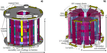
The assembly structure of the secondary windings, magnetic core, and the primary sub-windings in parallel of the TTMS is shown in Figure 2a. The total TTMS shown in Figure 2a contains Q batches of secondary windings distributing uniformly along the azimuthal direction of the magnetic core. Each batch of the secondary windings also consists of s branches of secondary sub-windings, while s and Q are both positive integers. Each branch of the secondary sub-windings goes in across the bottom of the n piles of the magnetic toroids, goes upward along the inner wall of the toroids, goes out across the top of the n piles of the toroids, and goes down along the outer wall of the toroids to form one turn of the secondary sub-windings. In the same law, another N s–1 turns of the secondary sub-windings are also formed along the anti-clockwise direction. Finally, the N s turns of one branch of the secondary sub-windings is formed with the output port fixing on the top of the n piles of the magnetic toroids. According to the laws aforementioned, other same branches of the secondary sub-windings are also formed one by one along the azimuthal direction of the magnetic core. The input ports of the s branches of the secondary sub-windings in the same batch are in parallel connection on a low-voltage (LV) copper sheet at the bottom of the magnetic core, as shown in Figure 2b. The output ports of the s branches of the secondary sub-windings in the same batch are also in parallel connection on a high-voltage (HV) copper sheet at the top of the magnetic core. So, Q batches of the secondary windings correspond to Q batches of LV copper sheets at the bottom and Q batches of HV copper sheets at the top. The Q batches of the secondary windings almost have the same geometric structure, so they have the same characteristic parameters. As all the Q batches of the secondary windings correspond to the same communal primary windings as shown in Figure 1, the proposed new TTMS shown in Figure 2a actually corresponds to Q batches of sub-TTMSs on a communal magnetic core. The total TTMS is fixed by two insulated support boards and three nylon support bars.
(Color online) The parallel combination structure of the secondary windings of the total TTMS (a) Assembly structure of the Q batches of the secondary windings and the magnetic core; (b) The distribution of the Q batches of the secondary windings with parallel combination structures, respectively.

Before the magnetic core saturates, the Q batches of sub-TTMSs boost and deliver high voltage pulses in Q branches synchronously. The equivalent turn number N p of the total primary windings of the TTMS is as N p = 1/n, and the Q batches of the secondary windings of the sub-TTMSs all have the same turn number as N s. The actual step-up ratio of each sub-TTMS is the same as (1/n): N s = 1:nN s. As a result, the sub-TTMSs are able to enhance the voltage by dozens of times while the turn number N s< 5. After the magnetic core saturates, the Q batches of sub-TTMSs working as Q batches of magnetic switches close synchronously. Because each batch of the secondary windings consists of s branches of secondary sub-windings in parallel and the turn number N s is small, the saturated inductance of the secondary windings of each sub-TTMS is low enough for magnetic switch. So, the proposed TTMS in this paper has high voltage step-up times and low saturated inductance (<1 μH) simultaneously.
Solid-State Marx Generator with Spark Gaps Substituted by the Sub-TTMSS
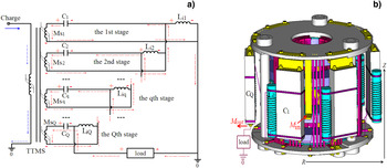
Figure 3a shows the equivalent schematic of the proposed new type of solid-state Marx generator based on TTMS. The Q-stage solid-state Marx generator consists of the TTMS, the Qstages of Marx capacitors C 1–C Q, the Qstages of grounded inductors L i1–L iQ, and a load. The Marx generator is formed by Q stages of basic Marx components in series such as the 1st stage … the qth stage … the Qth stage. q is a positive integer, and 1 ≤ q≤ Q. The qth basic Marx component consists of the qth Marx capacitor C q, the qth grounded inductor L iq, and the qth batch of the secondary windings of the TTMS working as the qth magnetic switch MSq. C q can be high-voltage pulse capacitor, PFL capacitor, or the total capacitor of pulse-forming network (PFN). When q = 1, the high-voltage pole of MS1 (or the first batch of the secondary windings of the TTMS) connects with the high-voltage pole of the first stage Marx capacitor C 1. The low-voltage pole of MS1 connects with ground, while the low-voltage pole of C 1 connects the first stage grounded inductor L i1. The low-voltage pole of L i1 is grounded. When 1 < q ≤ Q, the high-voltage pole of MSq connects with the high-voltage pole of the qth stage Marx capacitor C q. The low-voltage pole of C q connects the high-voltage pole of the qth stage grounded inductor L iq. The low voltage poles of L iq and MSq both connect with the low-voltage pole of the (q-1)th stage Marx capacitor C q-1. The load can be inductor, capacitor, resistor, or the combination of the three. The high-voltage pole of the load connects with the low-voltage pole of the Qth Marx capacitor C Q, and the low-voltage pole of the load is grounded. The input port M in of the proposed Marx generator is the same as the input port P in of the TTMS shown in Figure 1, and the output port M out of the Marx generator is at the low-voltage pole of the Qth Marx capacitor C Q.
(Color online) The equivalent schematic and structure of the proposed solid-state Marx generator based on the TTMS (a) The equivalent schematic of the proposed solid-state Marx generator based on the TTMS. (b) The assembly structure of the compact solid-state Marx generator.

Figure 3b shows the assembly structure of the proposed compact solid-state Marx generator based on the TTMS. The qth grounded inductor L iq is a solenoid inductor that connects the qth Marx capacitor C q to form the qth basic Marx component. The top of the qth basic Marx component connects with the qth batch of HV copper sheet through a “Z-type” metal sheet. All the Q batches of the basic Marx components have an uniform distribution along the azimuthal direction of the magnetic core, and the Q batches of the basic Marx components correspond to the Q batches of the secondary windings one by one.
The basic working principles of the Q-stage solid-state Marx generator are as follows. The external primary charging source is grounded through the primary windings of the TTMS. During the charging course, the primary charging current flows from the input port M in to the primary sub-windings in the parallel combination, and the magnetic core of the TTMS is reset by the primary charging current. After the primary charging course, the primary charging source discharges to the primary circuit of the TTMS to provide a low voltage pulse. Through the magnetic coupling of the windings of the TTMS, the Q batches of the secondary windings of the TTMS on the same magnetic core deliver Q batches of high voltage pulses with a synchronous accuracy in the ns range. The synchronous Q batches of high voltage pulses charge the Q batches of Marx capacitors in parallel. As the charging time of the capacitors is usually long in the μs range, the reactance of the grounded inductors of Marx generator is so small that the Marx capacitors can be charged in parallel. During the charging course of the Marx capacitors, the Q batches of the secondary windings of the TTMS play as Q batches of charging inductors in the Marx generator. As the charging course of the Marx capacitors goes on, the fact that the actual hold-off voltage-product of any one batch of the secondary windings reaches the allowed maximum value can cause forcible saturation of the magnetic core. As a result, the Q batches of the secondary windings which are on the same saturated core saturate synchronously. The saturation course of the core is so short that the reactance of the previous grounded inductors becomes large enough. The previous grounded inductors act as the isolating inductors, and the Q-stage Marx generator is established to work in the mode of discharge in series combination. As the saturation of the Q batches of the secondary windings has a synchronous accuracy at ns range, the establishing time of the Q-stage Marx generator is also at ns range. Finally, the Q-stage Marx generator discharges to the load to form high voltage pulse at hundred kV/hundred ns range.
In comparison with the common Marx generator technology, the proposed solid-state Marx generator based on the TTMS has advantages and specialties as follows. First, the structure that the TTMS with batches of windings in parallel combinations is used to substitute all the spark gaps in the Marx generator, makes sure that the establishing time of the Marx generator is at ns range. So, the proposed Marx generator has advantages of high-repetition rate, solid-state and long life time, in contrast to the common Marx generator based on spark gaps. Second, the proposed Marx generator based on the TTMS discards the external trigger system, the magnetic core is reset automatically, and the different batches of TTMSs operate automatically and synchronously. So, the structure and the synchronous controlling become simple and the cost of the switches decreases in a large scale, in contrast to the common Marx generator based on semiconductor switches. Third, the proposed Marx generator is a compact integration of the Marx generator and pulse transformer, which achieves an important advantage that the input voltage of Marx generator can remain at a low level less than 1 kV. Last, the batches of the secondary windings of the TTMS not only work as magnetic switches after the core saturates, but also act as the charging inductors of the Marx generator before the core saturates. So, the synchronously charged Marx generator abandons the common used charging inductors, in contrast to the common Marx generator.
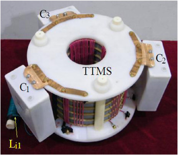
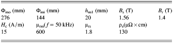
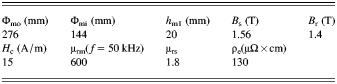
Through the technical scheme proposed in this paper, a three-stage solid-state Marx generator (Q = 3) is produced as shown in Figure 4. In the TTMS of the Marx generator, the magnetic core had six piles of iron-based amorphous toroids, and n = m = 6. Define the saturated magnetic induction intensity, residual magnetic induction intensity and the coercive force of the magnetic material of core in the TTMS as B s, B r, and H c, respectively. Define the unsaturated and saturated relative permeabilities of magnetic core as μrm and μrs, respectively, and the resistivity of magnetic material as ρe. The geometric parameters and magnetic properties of each pile of the magnetic toroid are shown in Table 1. In the TTMS, there were six one-turn primary sub-windings in the parallel combination. There were three (Q = 3) batches of the secondary windings of the TTMS, and each batch consisted of four (s = 4) branches of secondary sub-windings while N s = 4.75. Before the core saturated, the three sub-TTMSs all have the same step-up ratio as (1/6):4.75 = 1:28.5. Under the frequency condition that f = 50 kHz, the unsaturated inductance of the total primary windings of TTMS was as L p = 260 nH, the unsaturated inductance of each batch of the secondary windings was as L s = 200 μH, the mutual inductance of each sub-TTMS was as M = 7.2 μH, and the effective coupling coefficient of each sub-TTMS was as K eff = 0.998. In the three-stage Marx generator, the brick-like Marx capacitors were in the same norm as 350 nF/36 kV, and the geometric dimensions of each brick capacitor were as 180 × 152 × 70 mm. All the grounded inductances of the Marx generator were as 95 μH. The basic Marx components were connected in accordance with the schematic shown in Figure 3a.
(Color online) The produced three-stage solid Marx generator based on TTMS.

Geometric parameters and magnetic properties of the iron-based amorphous core employed in the TTMS
EXPERIMENTAL RESULTS AND DISCUSSION
Experimental results and analysis when pulse capacitor was used as load
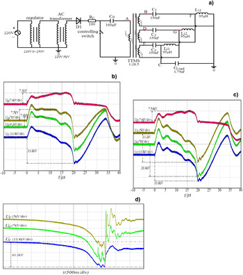
In the demonstration experiments, 1.75 nF/100 kV pulse capacitor C Load was used as the load of the three-stage Marx generator, in order to demonstrate the characteristics of discharging in series for voltage adding. The equivalent schematic of the total experimental setup is shown in Figure 5a. The primary charging source consisted of a voltage regulator, an alternate current transformer, a diode rectifier D 1, a charging resistor R c, a controlling switch, and a primary capacitor C 0. The 160 μF/3 kV primary capacitor C 0 can be charged to about 500 V–1 kV, and the charging current of C 0 reset the magnetic core. When the charging course of C 0 was over, the controlling switch closed and C 0 discharged to the TTMS. As the core had been resetalready by the previous charging current, the three sub-TTMSs all operated at the transformer mode, and the three stages of Marx capacitors C 1–C 3 were charged in parallel synchronously. After the core saturated, the three stages of Marx capacitors C 1–C 3 discharged to the load capacitor C Load in series, and the C Load was charged to a high-voltage level. As the demonstration experiment was mainly for tests of synchronization and voltage adding, no discharging switch for C Load was considered. The circuital parameters of the components are shown in Figure 5a.
(Color online) Schematic of the experimental setup of the three-satge solid Marx based on TTMS and the experimental results when load capacitor was used (a) Schematic of the experimental setup; (b) Voltage waveforms of U B, U C, U D, and U E at points B, C, D, E in the schematic, respectively, when C 0 was charged by 600 V; (c) Voltage waveforms of U B, U C, U F, and U G at points B, C, F, G in the schematic respectively, when C 0 was charged by 600 V; (d) Typical waveforms of U F, U G, and U C at points F, G, and C, when the magnetic core of the TTMS saturated deeply.

When the primary capacitor C 0 was charged at 600 V, the obtained voltage pulses at points B, D, E, and C in Figure 5a are as U B, U D, U E, and U C as shown in Figure 5b. When t < 0, C 0was charged and the magnetic core was reset. The voltage pulses such as U B, U D, and U E remained the amplitudes at 0. After the time t = 0, the controlling switch closed and the voltage pulses such as U B, U D, and U E rose synchronously, which demonstrated that the three stages of the Marx capacitors C 1–C 3 were charged in parallel synchronously. The amplitudes of U B, U D, and U E were about 7.3 kV, 7.5 kV, and 7.4 kV, respectively, which demonstrated that C 1–C 3 were charged uniformly. But the voltage on the Marx capacitor which was next to the load decreased in the later section of its charging course. As the charging circuit which consisted of C 0, the three sub-TTMSs and the Marx capacitors in parallel did not satisfy the dual resonant conditions, each of the sub-TTMS with theoretical step-up ratio as 1:28.5 actually obtained a step-up ratio as 1:12.3. During the synchronous charging courses of C 1–C 3, the load voltage pulse U C corresponded to the pre-pulse on C Load. C 1–C 3 were charged for about 18 μs, then the magnetic core that was divided into six batches saturated synchronously. The three batches of the secondary windings of the TTMS closed synchronously as three magnetic switches. C 1–C 3discharged to C Load in series, and the amplitude and rise time of load voltage pulse U C were about 33.8 kV and 1.5 μs, respectively. The main reason of the long pulse rise time was that the capacitances of the Marx capacitors C 1–C 3 were so large that the series-discharging periods were prolonged. If the capacitances of C 1–C 3 decreased to the 10 nF range, the pulse rise time of U Ccan decrease to hundred ns range. As the voltage amplitude of U C was larger than the sum of the amplitudes of U B, U D, U E, the proposed Marx generator realized the purposes of voltage adding and synchronous discharging. As to the primary charging voltage at 600 V, the total voltage step-up ratio of the proposed Marx generator was 1:56.3 in practice which is unmatchable for the common Marx generator.
In order to directly demonstrate the voltage adding phenomenon of the three-stage Marx generator, the voltage pulses on the points B, F, G, and C as shown in Figure 5a were also tested, and the output pulses of C 1–C 3 were defined as U F, U G, and U C, respectively. The charging voltage pulse U B on point B was tested as a referential pulse. When the primary capacitor C 0 was still charged at 600 V, the obtained typical pulses of U B, U F, U G, and U C are presented in Figure 5c. From the time that t = 0, C 1–C 3 were charged in parallel synchronously. From the pulse U B, C 1 was charged at 7.54 kV. During the charging course, the amplitudes of the pre-pulses of U F, U G, and U C were large. After the core saturated, C 1–C 3 discharged to the load capacitor in series, and the amplitudes of U F, U G, and U C were 13.2 kV, 20.4 kV, and 33.6 kV, respectively. The experimental results showed the phenomenon of voltage increasing stage by stage, and directly demonstrated the adding characteristic of the proposed Marx generator. Of course, the pulse rise time of the load voltage pulse U C was also relevant to the saturation state of the magnetic core in TTMS. When the core was in a deep saturated state, the saturated inductances of the magnetic switches in series decreased and the pulse rise time of U C also decreased. The typical U C pulse that corresponded to a deep saturated state of core is shown in Figure 5d. The amplitudes of U F, U G, and U C increased while the pulse rise time of U C decreased to a level less than 1 μs. The basic experimental results shown in Figure 5 demonstrated that the technical scheme of the proposed Marx generator was feasible.
Experimental Results and Analysis When Helical Blumlein Pulse-Forming Line was Used as Load
In the experimental setup shown in Figure 5a, the amplitude of pre-pulse on the load was high during the charging course of the Marx capacitors. Furthermore, the charged load capacitor C Loadcannot discharge to form high-voltage pulse with short rise time. So, an improved experimental setup that the proposed Marx generator was used to charge a helical Blumlein pulse-forming line (HBPFL) with a magnetic switch was put forward in this section, as the HBPFL had broad applications in high power pulse technology (Liu et al., Reference Liu, Cheng and Qian2009; Cheng et al., Reference Cheng, Liu, Qian and Zhang2009).
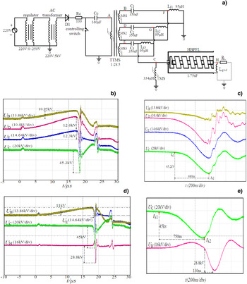
The equivalent schematic of the improved experimental setup is shown in Figure 6a, in which the primary charging source was the same as the one shown in Figure 5a. The load of the Marx generator was substituted by the HBPFL. The HBPFL consisted of an outer cylindrical conductor, a middle cylindrical conductor (helical conductor), and an inner cylindrical conductor. The equivalent capacitance, characteristic impedance, and electric length of the total HBPFL were about 1.75 nF, 160Ω, and 65 ns (Zhang et al., Reference Zhang, Liu and Fan2011a; Reference Zhang, Liu and Wang2011d; Zhang & Liu, Reference Zhang and Liu2012). A grounded inductor L gnd was used to connect with the outer cylindrical conductor and the inner cylindrical conductor, and the grounded inductance was 77 μH. A 160 Ω dummy load R L connected with the inner cylindrical conductor of the HBPFL. The high-voltage output port (point C) of the three-stage Marx generator connected with the helical conductor of the HBPFL so that the Marx generator can charge the HBPFL. A magnetic switch (MS) that acts as the main switch of the HBPFL connected on point C of the system, and iron-based nano-crystalline ribbon was employed as the core material of MS. The magnetic switch MS had five turns of windings, and its unsaturated inductance was 334 μH under the frequency condition f = 50 kHz. During the charging course of the Marx generator, MS was able to prevent the pre-pulse on HBPFL. The saturation time t s1 of the magnetic core of TTMS corresponded to the establishment of the Marx generator. After t s1, the Marx generator charged the HBPFL, and the MS also withstood the same high-voltage pulse on the HBPFL. When the HBPFL was charged to the time t s2, the withstanding voltage-product of the core of MS reached its allowed maximum value and the MS closed. The charged HBPFL began to discharge to MS and the high-voltage pulse with short rise time was formed on the dummy load R L.
(Color online) Experiments and results when the three-satge solid Marx based on TTMS charged the helical Blumlein PFL with a magnetic switch as the main switch; (a) Schematic of the experimental setup; (b) Voltage waveforms of U B, U C, U D, and U E at points B, C, D, and E in the schematic shown in Figure 6a, respectively, when C 0 was charged by 670 V; (c) An expanded display of Figure 6b; (d) Voltage waveforms of U B, U C, U E, and U H at points B, C, E, and H in the schematic shown in Figure 6a, respectively, when C 0 was charged by 670 V; (e) An expanded display of the U C and U H in Figure 6d.

First, the voltage pulses U B, U D, U E, and U C on points B, D, E, and Cin Figure 6a, respectively, were tested in experiment, in order to demonstrate the synchronization of switches and voltage adding of the Marx generator. When the 160 μF primary capacitor C 0 was charge to 670 V, and the typical voltage pulses U B, U D, U E, and U C are presented in Figure 6b. At the time t = 0, the controlling switch closed and the charged C 0 began to discharge to the primary circuit of the TTMS. From the waveforms of U B, U D, and U E, the Marx capacitors C 1–C 3 were charged synchronously. The charging courses of C 1–C 3 last about 17 μs, and the maximum charging voltage of U B, U D, and U E were as 10.95 kV, 12.6 kV, and 12.3 kV, respectively. During the charging course, the pre-pulse on the HBPFL can be neglected, from the pulse U C. After the core of the TTMS saturated, C 1–C 3 discharged in series and the HBPFL was charged. From the pulse waveform of U C, the charging amplitude of U C was 45.2 kV. Figure 6c shows an expanded display of the pulses shown in Figure 6b. From the expanded waveform of U C, the charging course last about 680 ns, from t s1 to t s2. When t = t s2, the peak charge voltage of U C reached 45.2 kV that was higher than the sum of the amplitudes of U B, U D, and U E. After t s2, the magnetic core of MS saturated, and the charged HBPFL discharged to MS. The experimental results demonstrated that the proposed Marx generator can not only realize the voltage adding, but also deliver high-voltage pulse with pulse rise time at several hundred ns range.
Under the same charge condition of C 0 at 670 V, the voltage pulses on the points B, E, C, and H are presented in Figure 6d as U B, U E, U C, and U H. During the charging course of the Marx generator, the pulse waveforms of U B and U H were in good superposition. The charging time of the Marx generator was also about 17 μs, and the charging amplitudes of U B, U E, and U C also remain unchanged in contrast to the results shown in Figure 6b. The peak amplitude of the U C was obtained as 45 kV. The same results of U B, U E, and U C shown in Figures 6b and 6d demonstrated that the outputs of the proposed Marx generator were stable under the same conditions. During the charging course, the pre-pulses on HBPFL and R L both can be neglected. Figure 6e shows an expanded display of the pulses of U H and U C shown in Figure 6d. From t s1 to t s2, the charging period of the HBPFL was about 750 ns and the peak charging voltage was 45 kV. After t s2, the MS closed, and the charged HBPFL discharged to MS while the main pulse U H was formed on load R L. From the waveform of U H, the pulse rise time was about 130 ns and the pulse amplitude was 28.8 kV. As the pulse rise time of U H was long, the pulse width at half maximum (PWHM) was prolonged to 200 ns. During the charging course of the HBPFL, the pre-pulse amplitude of U H was about 6.4 kV. The long pulse rise time of U H also caused the amplitude decrement of U H. If the charge voltage on the HBPFL was high enough, the magnetic core of MS could reach the deep saturation state so that the pulse rise time of U Hcould be shortened. The experimental results demonstrated the technical scheme that the proposed Marx generator based on the TTMS can be used to charge the HBPFL.
In conclusion, the proposed three-stage Marx generator based on the self-reset TTMS realized three most important goals. First, the Marx capacitors in parallel can be charged synchronously and uniformly, and the Marx generator had the establishing time in the ns range. Second, the Marx capacitors can synchronously discharge in series, and the voltage adding goal of the three-stage Marx generator was realized. Third, the proposed Marx generator was a compact integration device of the pulse transformer, magnetic switches and Marx generator. When the input voltage of the Marx generator was only 670 V, the three-stage solid-Marx generator can output high-voltage pulse with amplitude at 45 kV and the step-up ratio of the Marx generator reached 1:67.2. So, the Marx generator decreased the design difficulty and the cost of the primary charging source, and the high-repetition-rate operations of the Marx generator became easier and more perspective.
CONCLUSIONS
In this paper, a new kind of solid-state Marx generator based on synchronous TTMS is put forward, and the self-reset TTMSs with new winding structures are used to substitute all the spark gaps in the traditional Marx generator for the purposes of solidification and long life time. As the new type of TTMS with high stepup ratio and low saturated inductances is employed, the proposed Marx generator becomes a compact combination of pulse transformer, magnetic switch and Marx capacitors. The stages of the Marx capacitors can be synchronously charged in parallel before the magnetic core saturates, and these Marx capacitors also can synchronously discharge in series. The establishing time of the proposed Marx generator is at ns range. Experimental results demonstrated that when the input voltage of the Marx generator was 670 V, a three-stage solid Marx generator can output high-voltage pulse with rise time at 750 ns and amplitude at 45 kV. So, the three-stage solid Marx generator can enhance the voltage for about 67.2 times. The solid-state Marx generator also can be used as the voltage boosting device to charge the pulse-forming line at the hundred kV range.
ACKNOWLEDGEMENTS
This work is supported by the National Science Foundation of China under Grant No.51177167. It's also supported by the Fund of Innovation, Graduate School of National University of Defense Technology under Grant No.B100702. Furthermore, the work is supported by Hunan Provincial Innovation Foundation for Postgraduate under Grant No.CX2010B034.