
I. INTRODUCTION
In 2006, a novel class of superalloys was discovered by Sato et al. Reference Sato, Omori, Oikawa, Ohnuma, Kainuma and Ishida1 by their finding of a γ′-Co3(Al,W) phase with an L12 lattice structure in the ternary Co–Al–W system. For compositions exhibiting a γ-Co + γ′-Co3(Al,W) microstructure, the γ′-precipitates exhibit a cubic shape and are coherently embedded in a fcc γ-Co matrix. The precipitate sizes were in the range of some hundred nanometers with matrix channels of some ten nanometers in between and a γ′ volume fraction of up to 70%. Reference Bauer, Neumeier, Pyczak and Göken2,Reference Pollock, Dibbern, Tsunekane, Zhu and Suzuki3 Depending on the W content of the alloy, the solvus temperature of the γ′ phase can be higher than 1000 °C. Other alloying elements, as, for example, Ta and Ti, were also found to increase the γ′ solvus temperature. Reference Bauer, Neumeier, Pyczak and Göken2 Taking all these observations into account and keeping in mind that Ni-base superalloys, which exhibit similar microstructures and properties, are very successful high-temperature materials, the Co–Al–W system has a good potential to be an attractive material for high-temperature applications. Reference Suzuki, DeNolf and Pollock4–Reference Mughrabi8
Despite the high similarity of the γ/γ′ microstructures between these novel Co-base and the well-known Ni-base superalloys, the creep and high-temperature plastic deformation mechanisms seem to differ between the two alloy classes. In the high-temperature regime at around 850–1000 °C, creep deformation in Ni-base superalloys is dominated by the dislocation movement in the γ matrix channels. Reference Nabarro9,Reference Mughrabi and Tetzlaff10 Depending on the lattice mismatch between the γ matrix and γ′ phase and the externally applied stress, one orientation of matrix channels with respect to the externally applied stress deforms first, while plastic deformation in the other orientation of matrix channels is delayed. Dislocations moved up to the γ/γ′ interfaces rearrange there to build interfacial dislocation networks, which can partly compensate for coherency stresses between the γ matrix and γ′ precipitate phase. Reference Nabarro9,Reference Mughrabi and Tetzlaff10 Given a sufficiently high creep temperature, a process known as rafting also takes place, where the γ′ precipitates coarsen together. Reference Nabarro9,Reference Pollock and Argon11 This process generates a microstructure of γ′ plates perpendicular or γ′ rods parallel to the external stress axis, depending on the sign of the external stress and the γ/γ′ lattice mismatch. Reference Nabarro9,Reference Mughrabi and Tetzlaff10 With dislocations filling the matrix channels and the development of the raft structure, dislocation movement within the matrix channels and the transfer of dislocations from one orientation of matrix channels to the other become increasingly difficult. Reference Pollock and Argon12 Then also plastic deformation of the stronger ordered intermetallic γ′ phase is necessary. This happens by cutting through the γ′ rafts by pairs of ordinary dislocations with an antiphase boundary between them. Reference Pollock and Argon12,Reference Link and Feller-Kniepmeier13
γ′ hardened Co-base superalloys show some striking dissimilarities to the behavior of Ni-base superalloys. These differences are especially pronounced for ternary Co–Al–W alloys. It seems that dislocation activity is confined to only one orientation of matrix channels until plastic strains of up to at least 3–4%. Reference Pyczak, Bauer, Göken, Neumeier, Lorenz, Oehring, Schell, Schreyer, Stark and Symanzik14 These dislocations also do not form nicely ordered dislocation networks as seen in Ni-base superalloys. But, the most striking difference when compared to Ni-base superalloys is the large number of stacking faults in the γ′ particles, Reference Suzuki and Pollock5,Reference Pyczak, Bauer, Göken, Neumeier, Lorenz, Oehring, Schell, Schreyer, Stark and Symanzik14 which suggests that γ′ particles are frequently cut by super partials during creep deformation. Titus et al. Reference Titus, Eggeler, Suzuki and Pollock15 found superlattice intrinsic and extrinsic stacking faults in crept ternary and Ta-containing Co-base alloys. These facilitated γ′ cutting, and both W and Ta were found to segregate at these stacking faults. Reference Titus, Mottura, Viswanathan, Suzuki, Mills and Pollock16 The arrangement of these stacking faults locally changed the crystal structure to the D019-Co3W phase. Recently, Eggeler et al. Reference Eggeler, Müller, Titus, Suzuki, Pollock and Spiecker17 analyzed in high detail the structure of planar defects present in γ′ precipitates of a CoNi alloy and found them to be a complex arrangement of super partial and partial dislocations separated by the corresponding stacking faults and antiphase boundaries. Conclusively, it can be stated that the γ′ precipitate cutting by partial and super partial dislocations leaving respective planar faults within the γ′ particles is a common deformation mechanism during the creep of γ′-hardened Co-base superalloys. Unfortunately, not much data about the development of the microstructure and deformation structures during creep of γ′-hardened Co-base superalloys is available yet. Reference Pyczak, Bauer, Göken, Neumeier, Lorenz, Oehring, Schell, Schreyer, Stark and Symanzik14,Reference Shi, Yu, Cui and Sun18 To better understand and improve these alloys, it is of utmost importance to know if γ′ cutting or deformation of matrix channels by dislocations is the mechanism that takes place first during creep deformation. In addition, the onset of these different plastic deformation mechanisms with respect to the different stages of creep and the degree of rafting present in the material are of interest.
In the present work, creep tests performed on ternary Co–Al–W alloys were interrupted at different strains, and the crept material was investigated using scanning electron microscopy (SEM) and transmission electron microscopy (TEM).
II. EXPERIMENTAL
Three alloys with the nominal composition Co–9Al–xW (x = 8, 9, and 11; all in atomic percent) were initially prepared from their elements and cast as rods in an arc melting furnace. Subsequently, the material was used to cast single crystalline rods of 5 mm diameter using a pigtail grain selector in a Bridgman casting device at the University of Bayreuth. For sake of brevity, from now on these alloys will be termed 8W, 9W, and 11W. The material was solution heat-treated at 1300 °C for 12 h in a vacuum furnace. Subsequently, the material was aged at 900 °C for 200 h in air. From this standard heat-treated material, cylindrical creep compression specimens of 7.5 mm height and 5 mm diameter were prepared by electrodischarge machining and grinding. To ensure that the specimens are oriented parallel to the 〈001〉 direction, they were aligned using electron backscattered diffraction in the SEM prior to fabrication. Due to problems during the casting, only few specimens with suited 〈001〉 orientation could be prepared of 11W. Thus, the complete investigation program conducted on 8W and 9W could not be performed with 11W. 11W results are nevertheless included for comparison.
The compression creep tests were conducted in air using a Satec Systems creep machine (Instron, Norwood, Massachusetts) with a lever arm ratio of 16:1 at a temperature of 850 °C and a constant applied load corresponding to an initial stress of either 400 or 460 MPa.
For microstructure characterization sections of the crept specimens perpendicular to the stress axis and of the {100}/{010} plane parallel to the stress axis were cut. For SEM characterization, they were ground, mechanically polished, and finally electro polished for 90 s with a solution of 2-buthanol and perchloric acid in methanol at −41 °C using a voltage of 25 V. TEM specimens were prepared by cutting thin slices in the orientations mentioned above. These were mechanically ground down to a thickness of about 60 μm. Subsequently, these foils were electrolytically thinned to electron transparency with a Struers A3 electrolyte (Struers GmbH, Willich, Germany) and a voltage of 20 V at −38 °C.
For SEM investigations, a LEO Gemini 1530 SEM with a field emission gun (Carl Zeiss AG. Oberkochen, Germany) was used in the backscattered electron mode. TEM characterization was performed with a FEI (Hillsboro, Oregon) CM200 operated at 200 kV.
III. RESULTS AND DISCUSSION
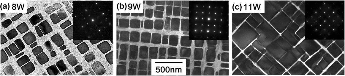
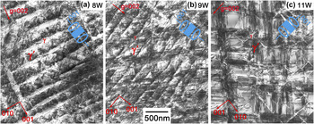
All three alloys exhibited a γ/γ′ microstructure with cubic γ′ precipitates in the state prior to creep testing. With increasing the W content, the fraction of the γ′ phase increased, the γ′ precipitates were bigger, and the matrix channels were narrower. Nevertheless, the differences in microstructure between 8W and 9W, which are the two alloys most thoroughly investigated in this work, were less pronounced than those between these two and 11W. In Fig. 1, the microstructures of the three alloys are imaged using TEM. The alloys 8W and 9W exhibit mostly cubic γ′ precipitates of about 100–200 nm in size that are aligned along 〈100〉 directions. The cube corners are rounded, and a number of precipitates deviating in size and shape from the average of about 200 nm cubes are interdispersed. The precipitates in 11W are larger with sharper corners [Fig. 1(c)]. In the broad matrix regions between the γ′ precipitates of 8W, a large number of secondary γ′ precipitates are visible, which were absent in 9W and 11W.
Microstructure of (a) 8W, (b) 9W, and (c) 11W after solution heat treatment and aging for 200 h at 900 °C, representing the microstructure prior to creep testing; the image was taken using TEM in the multibeam condition. The inset shows the corresponding diffraction pattern.

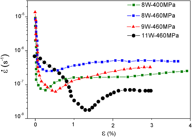
Figure 2 shows strain rate against strain
 $\left( {\dot \varepsilon – \varepsilon } \right)$
curves for creep tests performed at 850 °C on the 8W, 9W, and 11W alloys. As 8W exhibited worse creep resistance than 9W, in one test it was loaded to a stress of 400 MPa so that the time to 3–4% plastic strain was close to that for 9W loaded at 460 MPa. The creep tests were terminated at 3.9% plastic strain after 70 h for 8W under a load of 400 MPa and at 2.9% after 53 h for 9W under a load of 460 MPa. Both alloys show a primary creep stage with rapid hardening until they both reach a minimum creep rate of about 6 × 10⁻⁸ s−1. After that point, the specimens are softening. In 8W, this softening decelerates on further deformation to reach a nearly constant creep rate between about 1 and 4% plastic strain. On the contrary, the 9W specimen shows continuous softening after the creep minimum. When 8W was tested under a load of 460 MPa, it shows a less pronounced and a higher creep minimum of about 3 × 10⁻⁷ s−1, while the alloy 11W has a much higher creep resistance exhibiting a minimum creep rate of about 2 × 10⁻⁸ s−1 and a longer primary creep stage. The reason for the latter is unknown. The following more detailed characterization of the microstructure was restricted to interrupted tests of 8W under a load of 400 MPa and 9W under a load of 460 MPa.
Strain rate versus strain curves of 8W, 9W, and 11W tested at 850 °C.

Figure 3 shows SEM micrographs of specimens of 8W which were crept to different plastic strains. While the specimens after 0.07 and 0.45% of strain, the latter being about the creep rate minimum, show cubic shape and are aligned along different 〈001〉 directions in the specimens deformed to higher creep strains, a clear alignment perpendicular to the external stress axis is visible. In addition, some of the γ′ particles now appear elongated perpendicular to the stress axis probably because the former γ′ cubes have fused together. This process is well known from Ni-base superalloys as directional coarsening or rafting. Reference Nabarro9,Reference Mughrabi and Tetzlaff10,Reference Mughrabi, Arsenault, Cole, Gross, Kostorz, Liaw, Parameswaran and Sizek19,Reference Hammer, Mughrabi, Exner and Schuhmacher20
Microstructure development of γ′ precipitates in 8W after creep at 850° under 400 MPa to (a) 0.07%, (b) 0.45%, (c) 1.2%, and (d) 4% plastic strain.

The development of the γ/γ′ microstructure in the 9W alloy with increasing creep strain is shown in Fig. 4. The images correspond to creep specimens that were interrupted after 0.07, 0.4, 1.1, and 3% plastic strain. The specimen interrupted at 0.4% strain represents the microstructure near the minimum creep rate. As in the case of the 8W alloy, no preferential alignment along one of the 〈100〉 directions or rafting of γ′ precipitates is discernible before the minimum creep rate was attained in the 9W alloy at 0.4% creep strain. In the two specimens from tests that were terminated at strains of 1.1 and 3%, the γ′ precipitates align perpendicular to the external stress axis and coarsen together forming a rafted γ/γ′ microstructure.
Microstructure development of γ′ precipitates in 9W after creep at 850° under 460 MPa to (a) 0.07%, (b) 0.4%, (c) 1.1%, and (d) 3% plastic strain.

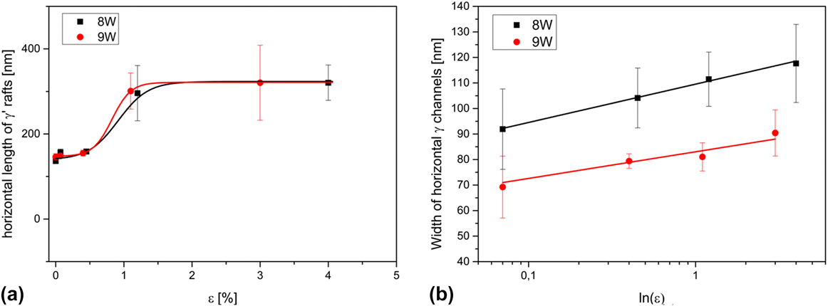
Thus the preferential direction for rafting was perpendicular to the external compressive stress axis for both alloys. In Ni-base superalloys, this is the expected direction for rafting under a compressive load for an alloy exhibiting a positive lattice mismatch between the γ and γ′ phases at the creep temperature. Reference Nabarro9 It is known for a Co-base ternary alloy with a similar composition to 9W that it had a positive lattice mismatch at 850 °C. Reference Pyczak, Bauer, Göken, Lorenz, Neumeier, Oehring, Paul, Schell, Schreyer, Stark and Symanzik21 Thus, it is assumed that also for 8W and 9W in the present study, the lattice mismatch was positive at the creep temperature. Qualitatively, it seemed that rafting of the γ′ particles took place after the creep minimum. To get quantitative data about the morphological development of the γ′ precipitates by line intersection method, the length of γ′ precipitates using the lines perpendicular to the external stress axis and the width of the matrix channels perpendicular to the external stress axis (i.e., horizontal) using lines parallel to the external stress axis were measured. In each alloy, at least 200 particles from four separate micrographs were considered. The respective results are shown in Fig. 5.
(a) Length of γ′ precipitates in crept specimens of the 8W and 9W alloys measured along the direction perpendicular to the external stress axis; (b) width of horizontal γ matrix channels in crept specimens of alloys 8W and 9W measured in the direction parallel to the stress.
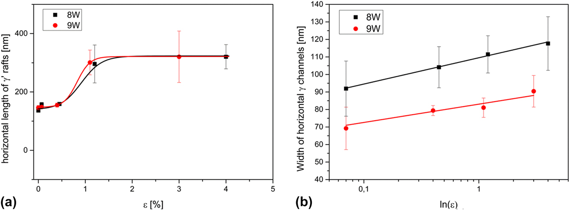
It is clearly visible that in both alloys the length of γ′ precipitates abruptly increases for strains larger than 1% [Fig. 5(a)]. This is in good agreement with the qualitative observation from the SEM micrographs. The abrupt increase of the γ′ length also hints to the fact that the rafting does take place by a meet and fusing together with adjacent γ′ particles as described by Nabarro Reference Nabarro9 for later stages of rafting. By such a process, the length of the precipitates increases strongly at the point where a fusing together Reference Nabarro9 or coalescence Reference Pollock and Argon11 takes place and afterward stays more or less on the same level. On the contrary as shown in Fig. 5(b), a linear increase of the width of the γ matrix channels perpendicular to the external stress axis (i.e., the matrix channels being horizontal in Figs. 3 and 4) when plotted over ln(ε) is found, as expected for a diffusion-controlled coarsening.
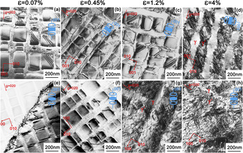
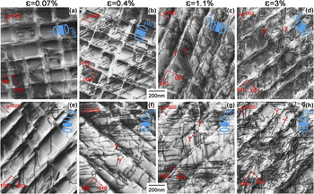
The development of the deformation structures in both alloys was characterized by TEM. Figure 6 shows micrographs of the crept 8W alloy after varying degrees of creep deformation. TEM images were taken from foils oriented parallel [Figs. 6(a)–6(d)] and perpendicular [Figs. 6(e)–6(h)] to the external stress axis. It is noteworthy that cutting of γ′ precipitates associated with stacking faults already takes place at a very low strain of 0.07%, [Fig. 6(a)] which is well within the primary creep regime. When compared to Ni-base superalloys, this is surprising as the onset of plastic deformation in the softer unordered matrix phase is expected to take place earlier, while the stronger ordered intermetallic γ′ precipitates tend to deform later. Reference Pollock and Argon12 This may indicate that at least in these ternary Co–Al–W alloys, the Co3(W,Al) L12 phase is much softer and more deformable relative to the Co-matrix than the corresponding Ni3Al L12 phase relative to the Ni-matrix in Ni-base superalloys. The occurrence of stacking faults will also be discussed later in relation to the W content of the alloys. Except for a subgrain boundary pictured in Fig. 6(e), which could also have been already present in the material prior to the creep test, the first signs of dislocation activity are found at 0.4% strain. At this strain, single nearly straight dislocation segments spanning over a number of matrix channels and γ′ precipitates are clearly seen in the γ matrix channels perpendicular to the stress axis [Fig. 6(f)]. As the creep strain increases to 1.2 and 4%, the dislocation activity in the matrix channels perpendicular to the stress axis [Figs. 6(g) and 6(h)] strongly increases. These dislocations are not straight and regular anymore but appear to have a kind of entangled irregular arrangement. Meanwhile the matrix channels parallel to the stress axis [Figs. 6(c) and 6(d)] are virtually free of dislocations.
Deformation structures of the 8W alloy—upper row: TEM foil parallel to stress axis (a) 0.07%, (b) 0.45%, (c) 1.2%, and (d) 4% plastic strain—lower row: TEM foil perpendicular to the stress axis (e) 0.07%, (f) 0.45%, (g) 1.2%, and (h) 4% plastic strain, deformed under a load of 400 MPa at 850 °C.

Figure 7 shows a series of TEM micrographs taken from interrupted creep specimens of the 9W alloy crept to 0.07, 0.4, 1.1, and 3% creep strains. The phenomena observed are generally similar to those seen in the 8W alloy. Again cutting of γ′ precipitates has already taken place during the initial stages of creep, as indicated by the presence of stacking faults [Fig. 7(a)]. Such γ′ precipitate cutting during the primary creep was already reported by Shi et al. Reference Shi, Yu, Cui and Sun18 for a more complex Co–Al–W–Ni–Ti alloy. Recently Zhou et al. also reported the occurrence of planar faults already during early creep deformation in a Co–Al–W–Ta–Ti alloy. Reference Zhou, Chang and Feng22 It is observable, especially in the specimens deformed up to higher creep strains that the dislocation activity in matrix channels perpendicular to the stress axis [Figs. 7(g) and 7(h)] is much stronger than in matrix channels parallel to the stress axis [Figs. 7(c) and 7(d)]. The latter appear to be nearly free of dislocations, which is similar to the observations in the 8W alloy. Nevertheless, in some details, the deformation structures in specimens of 9W and 8W alloys differ. The onset of dislocation activity takes place earlier in 9W, and some straight dislocation segments spanning over a number of γ′ precipitates and matrix channels are already visible in the primary stage of creep at 0.07% strain [Fig. 7(e)]. A strong dislocation activity in the matrix channels perpendicular to the stress axis is found in specimens deformed up to the creep minimum and above, i.e., to 0.4, 1.1, and 3% of strain, respectively, as is visible in Figs. 7(f)–7(h). Despite this strong dislocation activity, no well-developed dislocation networks as known from Ni-base alloys deformed under similar creep conditions have been found. However, some of the dislocation segments seemed to have interacted with each other forming rounded corners similar to dislocation arrangements already reported in a ternary Co–9Al–9W alloy earlier by Pyczak et al. Reference Pyczak, Bauer, Göken, Neumeier, Lorenz, Oehring, Schell, Schreyer, Stark and Symanzik14 and also observed during the first stages of dislocation network formation in Ni-base superalloys by Field et al. Reference Field, Pollockf, Murphy, Antolovich, Stusrud, MacKay, Anton, Khan, Kissinger and Klarstrom23 In general, the dislocation structure in 9W appears more regular than in 8W.
Deformation structures in alloy 9W—upper row: TEM foil parallel to stress axis (a) 0.07%, (b) 0.4%, (c) 1.1%, and (d) 3% plastic strain—lower row: TEM foil perpendicular to stress axis (e) 0.07%, (f) 0.4%, (g) 1.1%, and (h) 3% plastic strain, deformed with a load of 460 MPa at 850 °C.

The earlier onset of dislocation activity in one orientation of matrix channels can be explained by the combined effect of external applied stress and the coherency stresses, which are due to the γ/γ′ lattice mismatch. While in one orientation of matrix channels the coherency stress and the externally applied stress add up, they counteract each other in the other orientation of matrix channels. Dislocation activity starts in the orientation of matrix channels, where the coherency stress increases the externally applied stress causing a higher local stress and thus earlier plastic deformation. In the case of Co-base alloys deformed in compression, these should be the matrix channels perpendicular to the external stress axis, assuming, as is here the case, that the γ/γ′ lattice mismatch is positive at the creep temperature. While measurements of lattice mismatch at elevated temperatures are still scarce for Co-base superalloys, data available in the literature report positive values for Co-rich systems. Reference Bauer, Neumeier, Pyczak, Göken, Huron, Reed, Hardy, Mills, Montero, Portella and Telesman7,Reference Pyczak, Bauer, Göken, Neumeier, Lorenz, Oehring, Schell, Schreyer, Stark and Symanzik14,Reference Pyczak, Bauer, Göken, Lorenz, Neumeier, Oehring, Paul, Schell, Schreyer, Stark and Symanzik21,Reference Tanaka, Ooshima, Tsuno, Sato and Inui24,Reference Yan, Vorontsov, Coakley, Jones, Stone, Dye, Huron, Reed, Hardy, Mills, Montero, Portella and Telesman25 Nevertheless, no well-developed dislocation networks are observed. This could be explained by the role of the γ/γ′ lattice mismatch and the coherency stresses induced by it. When dislocation activity takes place in matrix channels, where the coherency stresses add up with the externally applied stress, the dislocations cause a plastic deformation that relaxes the coherency stresses. Thus, it is energetically favorable to store these dislocations at the γ/γ′ interfaces in a configuration of regular dislocation networks. Reference Field, Pollockf, Murphy, Antolovich, Stusrud, MacKay, Anton, Khan, Kissinger and Klarstrom23,Reference Feller-Kniepmeier and Link26 The higher the amount of γ/γ′ lattice mismatch the higher the driving force to build such regular dislocation networks. As already mentioned Co-base superalloys exhibit a positive lattice mismatch at room temperature, which decreases to smaller positive values with increasing temperature. Thus, the amount of lattice mismatch and the driving force to form dislocation networks is low. On the contrary, many Ni-base superalloys have a negative lattice mismatch at room temperature that becomes more negative with increasing the temperature (e.g., Ref. Reference Pyczak, Devrient, Mughrabi, Green, Pollock, Harada, Howson, Reed, Schirra and Walston27). Thus, the amount of lattice mismatch and the driving force to build regular dislocation networks increases with temperature in most Ni-base superalloys. This is a possible explanation why no regular dislocation networks are found in Co-base superalloys as compared to Ni-based superalloys. The amount of γ/γ′ lattice mismatch and, thus, the driving force to build regular dislocation networks are lower in the Co-based alloys. It should be noted that the easiness of γ′ cutting observed in these Co-based alloys Reference Tanaka, Ohashi, Kishida and Inui28,Reference Okamoto, Oohashi, Adachi, Kishida, Inui and Veyssière29 and discussed above may also contribute to the absence of regular dislocation networks. Dislocations stopped at the γ/γ′ interfaces could dissociate into partial or super partial dislocations, which are able to cut the γ′ precipitates and hence fewer dislocations remain at the γ/γ′ interfaces to form networks.
In Ni-base superalloys, it is commonly accepted that rafting of the γ′ phase is due to the presence of interfacial dislocation networks at the γ/γ′ interfaces. Reference Kraft, Altenberger and Mughrabi30,Reference Fährmann, Fährmann, Paris, Fratzl, Pollock, Kissinger, Deye, Anton, Cetel, Nathal and Woodford31 Nevertheless, it was predicted by Pineau Reference Pineau32 that purely elastic strains and stresses could also cause a rafting-like elongation of precipitates. For Co-base superalloys, it still has to be clarified whether the rafting observed during creep deformation is an effect of plastic deformation, i.e., the presence of dislocations at the γ/γ′ interfaces or caused by elastic distortions resulting from a lattice mismatch.
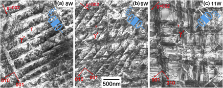
To investigate the role of the γ′ volume fraction on the deformation mechanisms during creep specimens from the 8W, the 9W, and 11W alloys that had been deformed to between 3 and 4% creep strain were compared using TEM. Micrographs from TEM foils that were perpendicular to the external stress axis (i.e., with viewing direction parallel to the external stress axis) are shown in Fig. 8. The most obvious difference between the alloys is an increase of stacking fault density, which increases in the order 8W, 9W, and 11W. There are two possible explanations for this. One possibility is that due to the different chemical compositions of the alloys, it may be easier to cut through the γ′ precipitates in higher W-containing alloys. Alternatively, to achieve a compatible deformation of both the γ and γ′ phases, it is necessary that more frequent γ′ cutting occurs in the alloy with the higher γ′ volume fraction. Normally, the former explanation could be ruled out because according to the ternary Co–Al–W phase diagram published by Sato et al., Reference Sato, Omori, Oikawa, Ohnuma, Kainuma and Ishida1 the chemical composition of the γ′ phase should not change significantly when the W content is changed within the γ/γ′ two-phase field. Thus, the γ′ phase in all three alloys should have a more or less similar chemical composition and, therefore, the ease of cutting the γ′ precipitates should be similar in all three alloys. Nevertheless, it is an ongoing discussion whether the γ′ phase is thermodynamically stable in the Co–Al–W system. Reference Pyczak, Bauer, Göken, Lorenz, Neumeier, Oehring, Paul, Schell, Schreyer, Stark and Symanzik21,Reference Kobayashi, Tsukamoto, Takasugi, Chinen, Omori, Ishida and Zaefferer33–Reference Lass, Williams, Campbell, Moon and Kattner35 If the γ′ phase is not stable, then the phase diagram of Sato et al. is not applicable. It is noteworthy in this case that Titus et al. Reference Titus, Mottura, Viswanathan, Suzuki, Mills and Pollock16 found that the cutting of γ′ particles could locally change the crystal structure to a D019 type. Therefore, the cutting of γ′ particles could be connected with the transformation from the metastable L12 Co3(Al,W) γ′ phase to the thermodynamically stable D019 Co3W phase, which could accelerate the process of γ′ cutting by super partial dislocations. Since the phase stability is expected to depend on the W concentration, differences in the stacking fault density and phase transformation kinetics between the alloys can easily be understood.
Deformation structures imaged in TEM foils orientated perpendicular to the stress axis in (a) the 8W alloy at 3.6% strain (460 MPa @ 850 °C), (b) the 9W alloy at 3% strain (460 MPa @ 850 °C), and in (c) the 11W alloy at 3.6% strain (460 MPa @ 850 °C).

IV. CONCLUSIONS
Ternary Co–Al–W alloys were creep deformed to analyze the plastic deformation mechanisms and development of the γ/γ′ microstructure during the different stages of creep. While some similarities to Ni-base superalloys with related microstructures were observed, the Co–Al–W alloys also showed features that are unique to this material class:
-
(1) Rafting of γ′ precipitates takes place after the minimum creep rate has been reached and the preferred orientation of the rafts is in accordance with the positive γ/γ′ lattice mismatch of the alloys at creep temperature.
-
(2) The cutting of γ′ precipitates by partial dislocations, which generates stacking faults in the γ′ particles is a process which already takes place during the early stages of creep deformation.
-
(3) Dislocation activity in the γ matrix is strongly confined to one orientation of matrix channels, where plastic deformation is favored due to the combined γ/γ′ coherency stresses and the externally applied stress.
-
(4) No formation of regular dislocation networks at the γ/γ′ interfaces is observed.
-
(5) Cutting of γ′ precipitates occurs more frequently in alloys with a higher W content and a higher γ′ volume fraction.