I. INTRODUCTION
The development of wireless technology in recent years has catapulted the demand for handheld devices to cover more than one frequency bands to support many wireless applications in commercial areas. Recently many antennas have been designed to satisfy the requirement of various wireless communication applications such as GSM, GPS, DCS, PCS, wireless local area network (WLAN), and WIMAX. An ideal possibility is to integrate the multiple bands in a single-antenna device offering various application frequency bands [Reference Elsadek1]. Antenna designed for handheld devices should have miniaturized size for space scarcity, a broad band coverage and a simple structure to fabricate which is cost effective. Micro strip printable antennas have low profile, simple to manufacture, and are more attractive to use.
Recently, many researchers are working on the transmission rate and to achieve spectral efficiency. One way to achieve a high data rate without extra radio frequency is the multiple-input–multiple-output (MIMO) technology [2]. In a rich scattering environment, MIMO system uses multiple antennas at the transmitter and the receiver sides, which overcome fading problem and also increase the data rate of transmission. Mutual coupling, isolation, correlation, diversity gain, and total array reflection coefficient (TARC) are the criteria for achieving a MIMO antenna performance. There is some trade-off in MIMO antenna systems, which increase the number of integrated antennas; diversity, and performance of MIMO get improved space constraints exist. Further, closely spaced devices undergo a series of mutual coupling effects, which affect channel capacity of MIMO system [Reference Abouda and Haggman3]. So, reduction of correlation and mutual coupling between elements are required for designing a MIMO antenna. There are several printed antennas for MIMO applications proposed as well [Reference Kharche4, Reference Karimian5]. MIMO antenna details for Bluetooth, WI-FI, WIMAX, and UWB applications are given in [Reference Kharche4]. They use two 90° angularly separated semi-circular monopole antenna with correlation coefficient of <0.02. In [Reference Karimian5], the proposed quad-band four-element MIMO antenna for the applications of WLAN and WIMAX, which uses slots for achieving four frequency band and correlation is <0.05. Also to improve isolation between the elements several techniques were provided [Reference Yang and Rahmat-Samii6–Reference Xias and Tang8]. Isolation between elements was also improved using electromagnetic band gap structures (EBG) [Reference Yang and Rahmat-Samii6]. Defected ground structures such as slots in ground plane [Reference Anitha, Sarin, Mohanan and Vasudevan7, Reference Xias and Tang8] were used to avoid mutual coupling effect significantly.
In this paper, we propose an independently tuning modified circular patch quad-band antenna for MIMO application. Here the design consists of two elements with slotted stubs, pulse shape stub for providing high isolation, and a four-element MIMO antenna system. The proposed design of two-element and four-element MIMO antennas has the following advantages compared with papers [Reference Abouda and Haggman3–Reference Xias and Tang8].
-
• Offer of operating frequency bands of GSM II (1.7–1.88 GHz), WIMAX (3.50–3.76 GHz), WLAN (5.25–5.38 GHz), and C band (7.15–7.35 GHz).
-
• Reduce edge to edge spacing between antenna elements, 5 mm (0.085λ).
-
• Low correlation achieved, <0.005 for two-element MIMO antenna, <0.005 for four-element MIMO antenna.
-
• Reduced mutual coupling, ≤−15 dB.
-
• Antenna structure achieved multiband, easy structure to fabricate.
This paper is organized as follows: Section II describes the antenna design, geometry, and the details of MIMO antenna. In Section III, the simulation results for the performance of the proposed quad-band antenna and MIMO antenna are discussed.
II. ANTENNA DESIGN CONFIGURATION AND DISCUSSION
A) Single-antenna element design
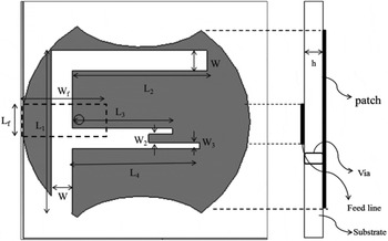
The configuration of the proposed single-element quad-band F slot antenna is shown in Fig. 1. In the proposed quad-band design antenna patch on one side of substrate and the feeder line on another side of the substrate and there is a via connected between the patch and the feeder. This via point acts as a ground for the proposed antenna. The circular patch of radius 16.4 mm using (1) from [Reference Balanis9], with dielectric constant of FR4 = 4.4 and height of the substrate (h) as 1.5748 mm.
 $$a = \displaystyle{F \over {{{\left\{ {1 + \displaystyle{{2h} \over {\pi a{\varepsilon _r}}}\left[ {\ln \left( {\displaystyle{{\pi a} \over {2h}}} \right)} \right] + 1.7726} \right\}}^{1/2}}}},\quad F = \displaystyle{{8.791 \times {{10}^9}} \over {{f_r}\sqrt {{\varepsilon _r}} }}.$$
Proposed single-element quad-band F-slot antenna. W f = 5.4 mm, L f = 10 mm, L 1 = 20 mm, L 2 = 19.4 mm, L 3 = 14 mm, L 4 = 18.4 m, W = 3 mm, W 1 = 0.854 mm, and W 2 = 1.25 mm.

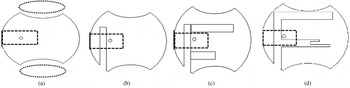
The step process to achieve a compact independent tunable quad band in F slot on modified circular patch antenna is shown in Fig. 2. There is a higher current density toward the edges in the circular patch, affecting the impedance bandwidth. So the semi-circular part with radius (10 mm) was removed from the upper and lower parts of the circular radiating patch to change it a modified circular patch. From simulations it is observed that removal of semi-circular part does not affect the resonant frequency of the element. The proposed design provides an independent frequency tuning of the interested band, by introducing an open-ended quarter-wavelength slot (λg/4 = 20 mm), where (λg(=c/(f√(ε eff ))) is guided wavelength at the operating frequency providing the frequency of interest at 4 GHz. The resonant frequency (f r1) and slot parameters can be related as shown in equations (2) and (3).
 $${f_{r1}} = \displaystyle{c \over {4{l_e}\sqrt {{\varepsilon _{eff}}} }},$$
 $${l_e} = \displaystyle{{{L_1}} \over W} - 0.6 + \displaystyle{{4l} \over {\sqrt {{\varepsilon _{eff}}} }},$$
where l is the correction coefficient and is predicted as 1.4535. Introduction of another short-ended quarter-wavelength (λg/4 = 19.4 mm) slot its frequency response is lie at 1.8 GHz. The resonant frequency (f r2) and slot parameters can be related as shown in equations (4) and (5).
 $${f_{r2}} = \displaystyle{c \over {4{l_e}\sqrt {{\varepsilon _{eff}}} }},$$
 $${l_e} = 2\left( {\displaystyle{{{L_2} + W} \over W} + \displaystyle{{4l} \over {\sqrt {{\varepsilon _{eff}}} }}} \right)\; .$$
Design step process of the proposed quad-band antenna from the single band to quad band. (a) Circular patch with single slot (antenna 1 with resonant frequency f r1). (b) Circular patch with dual slot (antenna 2 with resonant frequency f r2). (c) Circular patch with triple slots (antenna 3 with resonant frequency f r3). (d) Circular patch with the quad slot (antenna 2 with resonant frequency f r4).

Including one more short-ended one-eighth wavelength (λg/8 = 14 mm) slot offers frequency response at 5.4 GHz. The resonant frequency (f r3) and slot parameters can be related as shown in equations (6) and (7).
 $${f_{r3}} = \displaystyle{c \over {8{l_e}\sqrt {{\varepsilon _{eff}}} }},$$
 $${l_e} = \displaystyle{{{L_4}} \over {2W}} - 2l - 2.5 + \displaystyle{{8l} \over {\sqrt {{\varepsilon _{eff}}} }}.$$
For 7.2 GHz, half-wavelength (λg/2 = 18.4 mm) slot is introduced with existing ones. The resonant frequency (f r4) and slot parameters can be related as shown in equations (8) and (9).
 $${f_{r4}} = \displaystyle{c \over {2{l_e}\sqrt {{\varepsilon _{eff}}} }},$$
 $${l_e} = {L_4} - {L_3} + W + 1.3l + \displaystyle{{2l} \over {\sqrt {{\varepsilon _{eff}}} }}.$$
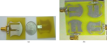
Thus, the combined modified circular patch quad-band antenna offers four bands at the frequencies of 1.8, 3.6, 5.4, and 7.2 GHz. The photography of the fabricated antenna is shown in Fig. 5.
B) Two-element multiband MIMO antenna
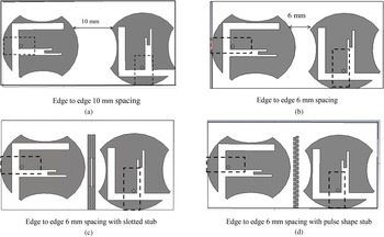
The independently tunable modified circular patch quad-band antennas can be used as compact array designs. A two-element array arrangement of antennas (shown in Fig. 1) is shown in Fig. 3(a). The array elements are arranged as orthogonal to each other to achieve polarization diversity. The independently tunable quad-band antennas are separated by 0.085λ (6 mm) as shown in Fig. 3(b). A number of simulations are performed to study the characteristics of the MIMO antenna and its dependency on spacing between the antenna elements. A distance of 10 and 6 mm is used in the prototypes and this is the minimum spacing distance between the array elements compared with works reported in [Reference Yang and Rahmat-Samii6]. The minimum spacing reduces the total dimensions of antenna elements. The dimension of two-element MIMO antenna is 1.11λ × 0.65λ × 0.026λ. Due to close spacing between the elements, they undergo series mutual coupling effects. Slotted and pulse-shaped stubs are introduced in the proposed MIMO antenna configuration [Reference Khan and Shafique10, Reference Arun, Sarma and Kanagasabai11]. It provides good isolation between two elements and is shown in Figs 3(c) and 3(d).
Proposed orthogonally placed two-element MIMO. (a) Edge-to-edge 10 mm spacing. (b) Four-element multiband MIMO antenna. (c) Edge-to-edge 6 mm spacing with the slotted stub. (d) Edge-to-edge 6 mm spacing with the pulse-shaped stub.

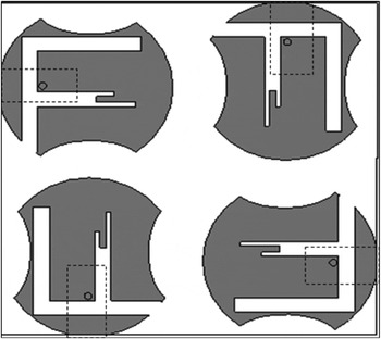
The configuration of a four-element MIMO antenna is shown in Fig. 4. The ports are placed on the four sides of the overall substrate. The separations between the elements are 0.085λ and the total dimensions of the four-element MIMO antenna is 1.199λ × 1.199λ × 0.026. (70 × 70 × 1.6 mm3). The prototype of the fabricated four-element MIMO antenna is shown in Fig. 5.
Configuration of the four-element MIMO antenna.

Photography of the fabricated proposed antennas (left, single-element antenna; right, four-element MIMO antenna).

III. RESULTS AND DISCUSSION
A) Single-element antenna
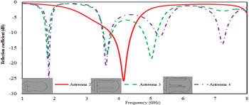
The simulated S-parameter characteristics of the proposed F-slot on a modified circular patch antenna from a single band to a quad band are shown in Fig. 6. The performance indicates that the introduction of each slots provide each band of operating frequency and thus independent frequency tuning can be achieved. As shown in Fig. 6, antenna 1 which has an open-ended quarter-wavelength slot in the modified circular patch resonates at 4 GHz. Then the introduction of two quarter-wavelength slot with the previous one provides response at 1.8 GHz along with 3.6 and 5.2 GHz as center frequencies covering applications bands of GSM II, LTE, and WLAN as shown in Fig. 6 of antenna 2. Another half-wavelength slot is introduced with the quarter-wavelength slot and gives response at 7.2 GHz which covers the C-band applications.
Simulation S-parameter characteristics of the proposed F-slot antenna from the single band to quad band.

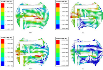
The surface current distribution of the proposed design at each frequency band of operation is shown in Fig. 7. The maximum current flow in the slot shows the responsibility of the slot. The surface current distribution of the proposed antenna investigates the mechanism of four operating frequency bands. The surface current distribution of1.8, 3.6, 5.2, and 7.2 GHz are shown in Figs 7(a)–7(d). The current path is maxima at the quarter-wavelength two slots which are responsible for the respective frequency bands.
Surface current distribution of the proposed design at the operating frequencies. (a) 1.8 GHz, (b) 3.6 GHz, (c) 5.4 GHz, and (d) 7.2 GHz.

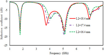
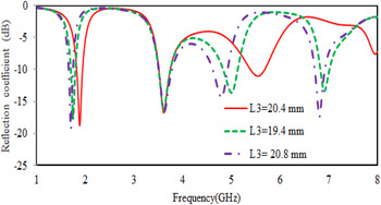
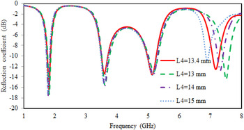
The parametric study of the proposed design is performed by varying the length of each slots and analysis of frequency tuning is studied. The independent frequency tuning of each band together with the effect of the introduction of each slot is studied by varying the length of each slots. The variation in the width of the slots plays a major role in impedance matching. The length of quarter-wavelength slot L2 is changed by keeping all other slot lengths constant, and the simulated S-parameter plot is shown in Fig. 8. Similarly Figs 9 and 10 show the frequency tuning while varying the lengths L3 and L4.
S 11 (dB) versus frequency in different value of L 2 provide tuning 3.6 GHz band with other bands are constant.

S 11 (dB) versus frequency in different value of L 3 provide tuning 5.4 GHz with other bands are constant.

S 11 (dB) versus frequency in different value of L 4 provide tuning 7.2 GHz band with other bands are constant.

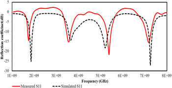
The proposed antenna is fabricated using a low-cost FR4 substrate. The comparison between simulated and measured reflection coefficient (S 11 in dB) performed in ANSOFT HFSS, and AGILENT network analyzer is shown in Fig. 11.
Simulated and measured S-parameter (|S 11|) of the proposed independent tunable quad-band slot antenna.

B) MIMO antennas
1) MUTUAL COUPLING AND ISOLATION
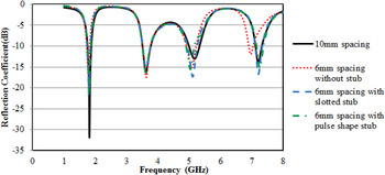
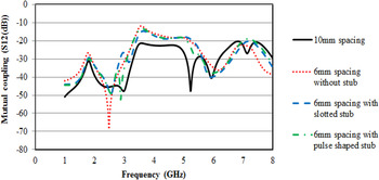
The mutual coupling between the elements in an array arrangement should be very low [Reference Kildal and Rosengren12]. The isolation between them should be high. Both are obtained from S ij of the scattering matrix. Figure 12 shows the simulated S-parameter of the proposed two-element MIMO antenna which offers quad-band frequencies. In a two-element array, mutual coupling of the 10 mm spacing is < −20 and 6 mm spacing is < −12 dB. Thus, the spacing between the elements should be more to avoid the effect of mutual coupling. But due to space scarcity, small devices require a minimum spacing for antenna. For balancing mutual coupling and the area, 6 mm spacing between the two elements can be used with isolating elements between the two-antenna elements to reduce the coupling effects.
Simulated S-parameter(S 11) of the two-element quad-band MIMO antenna.

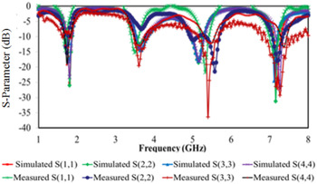
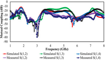
The mutual coupling of two elements with 6 mm spacing having a slotted stub is < −20 dB for all bands except 3.6 GHz frequency band and the pulse-shaped stub shows < −20 dB, which are shown in Fig. 13. The measured and simulated S-parameter and mutual coupling of four-element MIMO antenna are shown in Figs 14 and 15. In a four-element configuration, attempts are made to increase the number of elements in compact space without the neutralizing line, to analyze how it response. The four-element MIMO configuration without neutralizing line itself shows good response over mutual coupling < −15 to −80 dB. So analysis thereof with the neutralizing line could not be made. Also in highly compacted structures, neutralizing lines increase structure complexness and affect the radiation pattern of the radiating elements. Stoppage of four-element configurations with a neutralizing line is done for its reduction and easy fabrication.
Simulated mutual coupling (S 12) of the two-element MIMO antenna.

Measured and simulated S-parameters of the four-element MIMO antenna.

Measured and simulated mutual coupling of the four-element MIMO antenna.

2) ENVELOP CORRELATION COEFFICIENT (ECC)
The ECC is the important parameter of MIMO antenna characteristics which defines diversity. In uniform environment, correlation given with S-parameter [Reference Blanch, Romeu and Corbella13] as
 $${\rho _{eij}} = \displaystyle{{ \vert {s_{ii}} \times {s_{ij}} + {s_{ji}} \times {s_{jj}}{ \vert ^2}} \over {(1 - ( \vert {s_{ii}}{ \vert ^2} + \vert {s_{ji}}{ \vert ^2}))(1 - ( \vert {s_{jj}}{ \vert ^2} + \vert {s_{ij}}{ \vert ^2}))}}.$$
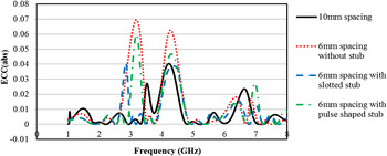
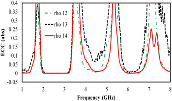
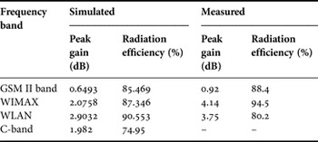
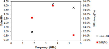
The simulated and measured gain and efficiency of the proposed quad-band antenna are shown in Table 1. The proposed antenna has an efficiency of 85.469%(simulation)& 88.4%(measurement) for GSM II band, 87.346%(simulation)& 94.5%(measurement) for WIMAX band, 90.553%(simulation)& 80.2%(measurement) for WLAN band. For measuring the reflection coefficient, the network analyzer support up to 8 GHz, so we use scattering parameters for measuring ECC of MIMO antenna are used. With this volume of radiation efficiency, calculation of the ECC using S-parameter for the MIMO antenna configuration is adequate. For the typical MIMO antenna performance ECC should be < 0.5. Figure 16 shows the ECC for two-element MIMO antenna for frequency ranges from 1 to 8 GHz using (10). It shows the correlation attains in the two-element MIMO antenna is ≤0.05. For four-element MIMO antenna also shows low ECC for all the bands. The correlation attained in the four-element MIMO antenna which is measured between ports 1 and 2 (ρ 12), between ports 1 and 3 (ρ 13), and between ports 1 and 4 (ρ 14) is shown in Fig. 17. The minimum correlation attained is < 0.005. There is no substantial reduction in the four-element array due to the closely spaced elements arrangement, but it shows |S ij | ≤ −15 dB due to elements are placed 90° to each other.
Simulated ECC for the two-element MIMO antenna.

Calculated ECC between antenna element 1 and antenna element 2 (ρ 12), between antenna element 1 and antenna element 3 (ρ 13), and between antenna element 1 and antenna element 4 (ρ 14) for fabricated four-element MIMO antennas

Proposed quad-band antenna performance.

3) TARC
For a single-port antenna, |S 11| is enough to characterize the performance of the antenna. For multiport antenna TARC is used for accurate characterization of the radiation efficiency and bandwidth of MIMO antenna. TARC is given as ratio of reflected power and incident power [Reference Sung ho14]. For N × N port network the TARC is given as,
 $$\Gamma _a^t = \sqrt {\displaystyle{{ \vert {s_{ii}} + {s_{ij}} \times {e^{j\theta}} { \vert ^2} + \vert {s_{jj}} + {s_{ji}} \times {e^{j\theta}} { \vert ^2}} \over 2}}.$$
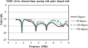
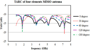
TARC for two-element MIMO antenna without stub and with pulse-shaped stub is shown in Fig. 18. The two-element MIMO design shows < −10 dB TARC while providing the reduced mutual coupling effect. The four-elements arranged MIMO antenna also showed < −10 dB TARC even in its compact spaced design. Figure 19 shows the TARC for four-element antenna array with different phases of incident power.
TARC for the two-antenna system with different phases of incident power.

TARC for the two-antenna system with different phases of incident power.

C) Radiation pattern analysis
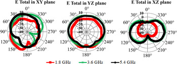
The two-dimensional (2D) measured and simulated radiation pattern of the proposed single-element design in XY, YZ, and XZ planes is shown in Fig. 20. This pattern shows the slightly omnidirectional pattern in the YZ plane for three bands with a maximum peak gain 2 dbi. In XY and XZ planes, it is directional one 3.6 and 5.4 GHz and omnidirectional for 1.8 GHz. The simulated and measured gain and efficiency of the proposed quad-band antenna is shown in Table 1. The proposed antenna has an efficiency of 85.469%(simulation)& 88.4%(measurement) for GSM II band, 87.346%(simulation)& 94.5%(measurement) for WIMAX band, and 90.553%(simulation)& 80.2%(measurement) for WLAN band (Fig. 21).
Measured and simulated radiation pattern in the XY, YZ, and XZ planes for the proposed antenna with operating frequency of 1.8, 3.6, and 5.4 GHz.

Measured gain and radiation efficiency performance of the fabricated antenna.

IV. CONCLUSION
The compact modified circular patch quad-band slot antenna for MIMO applications is proposed and fabricated. Measured single element offered four bands in the frequency of 1.8 GHz (1.7–1.88 GHz), 3.6 GHz (3.50–3.76 GHz), 5.4 GHz (5.25–5.38 GHz), and 7.2 GHz (7.15–7.35 GHz) covering wireless applications. Two-element and four-element MIMO antennas with reduced spacing between the elements have been presented. Studies on the spacing between the antenna elements and its effects on the performance of MIMO system has been discussed. With reduced spacing between the elements (0.089λ), low correlation is achieved. The simulated and measured results of the two-element and four-element MIMO systems achieved ≤0.005 correlation, ≤−15 dB mutual coupling and 9.999 dB diversity gain in interested operating bands.
ACKNOWLEDGEMENTS
Our special thanks to Mr. Muhammed Hussain of HCL Technologies at Ambattur for helping to do experimental work (radiation pattern) in HCL Pvt. Ltd.
 Chithradevi R., received B.E. degree in Electronics and Communication Engineering and the Master of Engineering in VLSI design from Anna University, Chennai, India in 2005 and 2007, respectively. She is currently working toward Ph.D. degree at SSN College of Engineering, Chennai. Her primary research interests are Multiband antennas and EBG structures for wireless communication applications.
 Nafiza N. received B.E. degree in Electronics and Communication Engineering and the Master of Engineering in Communication systems from Anna University, Chennai, India in 2013 and 2015, respectively. Her main research interests are design and development of smart antennas for wireless applications.
 Sreeja B.S. received her B.E. from Bharathidasan University in 2002, M.E. and Ph.D. degrees from Sathyabhama University in the years 2004 and 2012. She has 12 years of teaching experience in various universities, including Sathyabama University, India, Linton University College, Malaysia, and SSN College of Engineering, India. Her research interests include High-frequency devices and structures, Smart devices, MEMS and NEMS devices, and Co-integration of devices and circuits.
 Radha S., is the Professor & Head of Department of ECE, and has 24 years of teaching and 11 years of research experience in the area of Mobile Ad Hoc Networks. She has graduated from Madurai Kamraj University, in Electronics and Communication Engineering during the year 1989. She has obtained her Master degree in Applied Electronics with First Rank from Government College of Technology, Coimbatore and Ph.D. degree from College of Engineering, Guindy, Anna University, Chennai. She also worked as a visiting researcher at Carnegie Mellon University, USA for a period of 6 months in the area of Wireless Sensor Networks. She has 72 publications in International and National Journals and conferences in the area of Mobile ad hoc Network and Wireless Sensor Networks. She has received IETE – S K Mitra Memorial Award in October 2006 from IETE Council of India, Best paper awards in various conferences, and CTS – SSN Best Faculty Award – 2007 & 2009 for the outstanding performance for the academic years 2006–2007 and 2008–2009.