I. INTRODUCTION
Atomic layer deposition (ALD) is a variant of chemical vapor deposition (CVD) techniques capable of angstrom-resolution, layer-by-layer growth of compound films.Reference Ahonen, Pessa and Suntola1–Reference George4 ALD can deposit these ultrathin films in a conformal manner over a wide range of materials and high-aspect-ratio topographies. It has been used extensively in commercial production, most notably for high-permittivity gate insulators in 45-nm-node silicon transistors.Reference Mistry, Allen, Auth, Beattie, Bergstrom, Bost, Brazier, Buehler, Cappellani, Chau, Choi, Ding, Fischer, Ghani, Grover, Han, Hanken, Hattendorf, He, Hicks, Huessner, Ingerly, Jain, James, Jong, Joshi, Kenyon, Kuhn, Lee, Liu, Maiz, McIntyre, Moon, Neirynck, Pae, Parker, Parsons, Prasad, Pipes, Prince, Ranade, Reynolds, Sandford, Shifren, Sebastian, Seiple, Simon, Sivakumar, Smith, Thomas, Troeger, Vandervoorn, Williams and Zawadzki5, Reference Bohr, Chau, Ghani and Mistry6 Beyond its adoption by the microelectronics industry, this versatile technique finds broad application in surface modification, lithographic patterning, optical tuning, layer-by-layer optical characterization, and protection and encapsulation of various nanostructures. This review focuses on these new and emerging applications, particularly in plasmonics and nanobiotechnology, and summarizes some recent researches.
In a typical ALD reaction for depositing a binary compound film, the precursors “A” and “B” are sequentially introduced into a reaction chamber with an inert purging step in between: A/purge/B/purge/A/purge, etc. until the desired thickness is reached. An archetypical ALD process is the deposition of Al2O3 from trimethylaluminum (TMA) and H2O, which consists of four stepsReference Puurunen3: (i) inject the first precursor (TMA) until its binding sites on the reaction surface are saturated, (ii) purge the chamber with inert gas and remove unbound precursor, (iii) inject the second precursor (H2O) and form a monolayer of hydroxyl (OH) groups on the surface, and (iv) purge. Each growth step self-saturates when the surface binding sites are occupied; thus, the deposited film thickness after each cycle is highly reproducible. The total film thickness can be tuned in a stepwise manner by the total number of each atomically thick ALD cycle. Importantly, the film thickness can be precisely controlled over a large area, regardless of the underlying topography, because the self-saturating growth mechanism will even out nonuniform local growth rates. Additionally, the chemical reactions in ALD occur only on surfaces, and not in the gas phase, because the precursors are injected alternately and do not mix with each other. This scheme prevents unwanted particle generation caused by gas-phase reactions and also allows the use of highly reactive precursors such as TMA, which are difficult to use with CVD. By utilizing these highly reactive precursors, many ALD reactions can be performed at temperatures around 50–250 °C, well below typical CVD temperatures. Thus, ALD is an ideal method to deposit dense and conformal films on polymer, plastic, or even biological samples that cannot withstand high temperatures.
One drawback of ALD—although it may also be considered one of its key benefits—is its slow deposition rate, which is often an order of magnitude lower than the CVD rate. Usually, only a fraction of a monolayer is grown in each cycle because of steric hindrance of precursor molecules on the surface.Reference Puurunen7 Fortunately, many applications in microelectronics, and now in plasmonics, require ultrathin (e.g., <10 nm) films, thus throughput is not a major problem. Common materials that can be deposited via ALD are Al2O3, HfO2, ZrO2, TiO2, SiO2, and some metals such as Cu, Co, Fe, Ni, and Ag.Reference George4, Reference Lim, Rahtu and Gordon8, Reference Maarit Kariniemi, Niinistö, Hatanpää, Kemell, Sajavaara, Ritala and Leskelä9 For comprehensive reviews on the specific chemistry of the ALD process, the reader is directed to several excellent articles.Reference Leskela and Ritala2–Reference George4, Reference Ritala and Leskela10–Reference Kim, Lee and Maeng15
Although ALD, or atomic layer epitaxy as it was called initially, has been used for commercial production of thin film electroluminescent flat-panel displays,Reference Leskela and Ritala2 its use has more recently marked an important milestone. Following decades of intense R&D,Reference Wilk, Wallace and Anthony16 in some leading-edge microprocessors, ALD-grown high-permittivity (or “high-k”) insulators have replaced SiO2 gate insulators, which leak very high tunneling currents below a thickness of ∼10 Å.Reference Mistry, Allen, Auth, Beattie, Bergstrom, Bost, Brazier, Buehler, Cappellani, Chau, Choi, Ding, Fischer, Ghani, Grover, Han, Hanken, Hattendorf, He, Hicks, Huessner, Ingerly, Jain, James, Jong, Joshi, Kenyon, Kuhn, Lee, Liu, Maiz, McIntyre, Moon, Neirynck, Pae, Parker, Parsons, Prasad, Pipes, Prince, Ranade, Reynolds, Sandford, Shifren, Sebastian, Seiple, Simon, Sivakumar, Smith, Thomas, Troeger, Vandervoorn, Williams and Zawadzki5, Reference Bohr, Chau, Ghani and Mistry6 In addition, ALD can be used to make capacitors for dynamic random-access memory (DRAM) and thin barrier layers as well as seed layers for copper interconnects.Reference Kim12
Besides these mature applications in the microelectronics industry, ALD has tremendous potential for nanosciences and biotechnology to coat, functionalize, or protect a diverse set of substrates such as semiconductors, glasses, oxides, metals, polymers, carbon nanotubes, or graphene. Additionally, ALD has an unmatched capability to conformally cover, encapsulate, or fill high-aspect-ratio nanostructures such as wires, gaps, pores, or deep trenches. In particular, the capability of ALD to deposit ultrathin insulators on patterned metallic surfaces at low temperatures is essential for many applications in plasmonics and biotechnology.
II. ALD FOR PLASMONICS
Plasmonics is a rapidly growing branch of photonics that harnesses hybrid electromagnetic waves known as surface plasmon polaritons (SPPs), which are density fluctuations of conduction electrons in metals and propagate along the metal surface like ripples on a pond. Unlike free-space light, however, SPPs are bound to the interface and decay exponentially perpendicular to the metal–dielectric interfaceReference Ritchie17 and are not limited by diffraction. Indeed, it has been shown that metallic gaps, tips, apertures, wires, or particles can concentrate SPP waves to nanometric volumes, thereby enhancing light–matter interactions at unprecedented scales. The nanoscale manipulation of optical energy via SPPs can benefit a wide range of applications in sensing, imaging, spectroscopy, and lithography. Many review articles provide in-depth coverage of recent advances in plasmonics.Reference Barnes, Dereux and Ebbesen18–Reference Novotny23
A. ALD for characterization and tuning of optical nanostructures
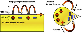
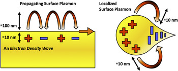
In addition to SPPs propagating on flat or smoothly varying topographies, another important class of plasmon waves is the “localized” surface plasmons (LSP) as illustrated in Fig. 1. The wave-like SPPs propagate along the metal surface and extend ∼100–300 nm perpendicular to the metal surface for the visible frequencies. In contrast, LSPs are bound to sharp metallic tips, corners, nanoparticles, or other nanoscale patterns and can confine optical energy more tightly with a shorter decay length of 10–50 nm. For both SPPs and LSPs, the maximum field intensity is at the metal surface.
Schematics of propagating surface plasmons, known as surface plasmon polaritons (SPPs) and localized surface plasmons (LSPs). Although SPPs propagate along the metal surface and decay exponentially in the perpendicular direction with a decay length of 100–300 nm in the visible frequencies, LSPs are more tightly bound on metallic nanostructures with a shorter decay length (10–50 nm).
Since SPPs are hybrid waves generated by a coupling between light and the conduction electrons, they have higher momentum than free-space light. Thus, excitation of SPPs requires increasing the momentum of light by illumination of a thin metallic film through a prism in a total internal reflection mode or by grating coupling with patterned metallic surfaces.Reference Raether24 If the surrounding environmental refractive index changes, e.g., due to molecular binding, the excitation condition, e.g., the surface plasmon resonance (SPR) angle or wavelength, will also change. Likewise, the resonant frequency of LSP resonance (LSPR) is also extremely sensitive to changes in surface properties, such as the dielectric constants, roughness, molecular adsorption, etc. Therefore plasmons can serve as efficient probes for surface-based phenomena that are difficult to detect with other techniques based on free-space light. In fact, SPR biosensors have been successfully commercialized and used extensively in pharmaceutical research to measure molecular binding kinetics.Reference Homola25, Reference Cooper26 SPR biosensors measure changes in the dielectric constant near metallic surfaces caused by molecular binding interactions. Because most proteins have refractive index values of 1.4–1.6,Reference Armstrong and Budka27, Reference Voros28 a thin layer adsorbed on the surface will increase the local refractive index and increase the SPR angle or wavelength.
Quantitatively, Jung et al.Reference Jung, Campbell, Chinowsky, Mar and Yee29 derived a formula to estimate the effective refractive index of a thin film, e.g., a molecular monolayer, seen by the SPP waves:

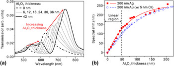
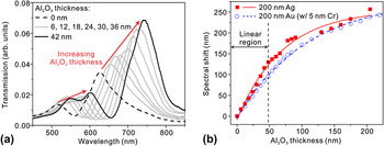
where n film and n medium are the refractive indices of a thin film deposited on the metal and of the surrounding medium, respectively, and d is the thickness of the deposited film. From Eq. (1), it can be seen that n effective changes gradually from n medium to n film with the increasing film thickness d. The decay length, δ SP, is a function of the frequency and the geometry of the metal structure. For example, propagating SPPs have δ SP around 100–300 nm in the visible regime. Since δ SP is also a measure of the probing range of a given SPR sensor, any spectral shift occurs mainly for film thicknesses up to δ SP and then saturates. Because ALD can deposit conformal overlayers with a thickness resolution well below δ SP, it provides a unique method to measure both the spectral response and probing range of SPR sensors. Such layer-by-layer spectral characterization, up to hundreds of nanometers in thickness, cannot be performed with real biomolecules. ALD-grown Al2O3 films have been used for distance-dependent studies of nanoparticle-based LSPR sensorsReference Whitney, Elam, Zou, Zinovev, Stair, Schatz and Van Duyne30 and nanohole-based SPR sensors.Reference Im, Lindquist, Lesuffleur and Oh31 Like metallic nanoparticles, the inverse structure, i.e., nanohole arrays in metallic films can also be used for biosensing based on the extraordinary optical transmission effect.Reference Ebbesen, Lezec, Ghaemi, Thio and Wolff32–Reference Lindquist, Lesuffleur, Im and Oh40 Light transmitted through metallic nanoholes has a characteristic spectrum based on the hole size, hole periodicity, and other geometrical parameters. Molecules binding to the nanohole film cause the transmission spectrum to shift. This is due to a change in the local refractive index, as with conventional SPR sensors. As shown in Fig. 2, the probing ranges of SPPs in metallic nanohole arrays can be determined from their spectral response to Al2O3 overlayers.
(a) Sequence of transmission spectra through a nanohole-based surface plasmon resonance (SPR) sensor as the thickness of atomic layer deposition (ALD)-grown Al2O3 overlayer increases from 0 to 42 nm in steps of 6 nm. (b) The spectral response of Au and Ag nanohole-based SPR sensors as the thickness of Al2O3 overlayer deposited on the surface increases. Both nanohole SPR sensors show a linear response to the thickness increases of Al2O3 layer up to 48 nm. Adapted from Im et al.Reference Im, Lindquist, Lesuffleur and Oh31
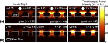
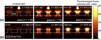
Because n effective seen by the evanescent wave changes from n medium (e.g., air or water) to n film as a function of the film thickness, ALD coatings can also be used for precise spectral tuning. Yang et al.Reference Yang, Chen, Husko and Wong41 showed digital tuning of photonic crystal devices, and Qian et al.Reference Qian, Shen, Qin and Das42 used ALD-grown titania shells to tune the LSPR peaks of Au nanoparticles. Experiments and three-dimensional computer simulations (Fig. 3) have shown that successively thicker ALD overlayers can be used to boost the optical transmission through an array of metallic nanoholes by matching the effective refractive index of the top surface with that of the glass substrate.Reference Im, Lindquist, Lesuffleur and Oh31
(a) Three-dimensional finite-difference time-domain (FDTD) computer simulations showing the time-averaged SP field intensity for different bulk refractive indices changing from 1.35 to 1.55. The maximum transmission occurs when the bulk refractive index matches with that of the glass substrate, 1.45. (b) An ALD overlayer can be also used to match the effective refractive index of the top surface with that of the glass substrate to boost the optical transmission through a metallic nanohole array. Adapted from Im et al.Reference Im, Lindquist, Lesuffleur and Oh31
Metallic structures have also been widely used in surface-enhanced Raman spectroscopy.Reference Jeanmaire and Van Duyne43 Raman spectroscopy is a powerful method for the detection of molecules by their signature vibrational (Raman) spectra. Raman spectral intensity is enhanced when molecules are within a few nanometers of a roughened metal surface, a process known as surface-enhanced Raman spectroscopy or SERS. Because of the strong electromagnetic fields around metallic nanostructures, electromagnetic enhancement is the largest contributor to the surface enhancement effect. Because the electromagnetic field of the illuminated plasmonic nanostructures decays exponentially with distance, the enhancement of Raman scattering sharply changes with the distance between proximate molecules and the metal surface. Dieringer et al.Reference Dieringer, McFarland, Shah, Stuart, Whitney, Yonzon, Young, Zhang and Van Duyne44 used an ALD-grown Al2O3 film as a spacer to map the SERS signal intensity as the distance between the analyte molecule and the Ag surface increased. Their results showed that the Raman signal intensity decreased 10-fold for every 2.8 nm increase in the Al2O3 film thickness. However, because ALD alumina films can be grown with ∼1 nm thicknesses, they can still act as a buffer layer to attach molecules without sacrificing the surface-enhanced Raman signal intensity.
B. ALD for protecting metallic nanostructures
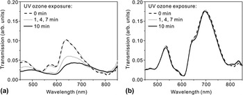
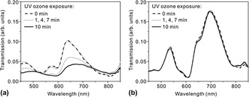
ALD-grown films can also act as a robust protection layer for metallic nanostructures. Au and Ag have been commonly used to build plasmonic devices operating in the visible or infrared regime. At wavelengths below ∼600 nm, however, Ag exhibits lower ohmic losses and lower SP damping than Au. Also, Ag is much less expensive than Au. Despite these advantages, Ag has poor chemical stability and is readily oxidized in the air. Therefore, many plasmonic devices, including the commercial Biacore SPR sensor chips (GE Healthcare, Waukesha, WI), are made with Au. Fortunately, the chemical stability of Ag surfaces can be improved by adding a protective layer. For plasmonic applications, the protective layer should be much thinner than δ SP, i.e., below 10–20 nm, otherwise the evanescent SP field will be buried in that layer. For such an ultrathin film to function as a barrier, it must be very dense, pinhole-free, and entirely encapsulate the patterned metals with excellent step coverage. Furthermore, the film should be deposited at a low temperature to avoid degrading or oxidizing the underlying Ag film during a deposition process. ALD can meet all of these stringent requirements unlike CVD or physical vapor deposition. Among various materials, Al2O3 has been widely investigated as a gas diffusion barrier.Reference Groner, George, McLean and Carcia45 Al2O3 film has a high phase-transition temperature of ∼800 °C and can improve the thermal stability of the underlying Ag films while blocking the diffusion of O2 and H2O. A low-temperature ALD process at 58 °C to coat poly(ethylene terephthalate) (PET) bottles with 360 Å of Al2O3 was shown to reduce CO2 gas diffusion rates compared with uncoated PET bottles.Reference Groner, Fabreguette, Elam and George46 In other examples, Al2O3 was used to encapsulate and prevent oxidation of organic light-emitting devices. In the context of plasmonics, groups have used Al2O3 to improve the thermal and chemical stability of Ag-based nanostructures.Reference Im, Lindquist, Lesuffleur and Oh31, Reference Whitney, Elam, Stair and Van Duyne47–Reference Barrios, Malkovskiy, Kisliuk, Sokolov and Foster49 Whitney et al.Reference Whitney, Elam, Stair and Van Duyne47 showed that Ag nanoparticles coated with a sub-1-nm-thick Al2O3 capping layer can preserve plasmon resonance peaks even after annealing at 500 °C, while the same structure without ALD coating showed degraded peaks after annealing at only 200 °C. Likewise, Al2O3-coated Ag nanoparticles showed improved stability against local heating induced by a high-power femtosecond laser.Reference Sung, Kosuda, Zhao, Elam, Spears and Van Duyne48 In terms of chemical stability, it has been shown that Al2O3 overlayers can protect Ag-based SERS substrates with no appreciable decline in performance after 9 months of storage in ambient conditions. This suggests that ALD-coated Ag substrates may be suitable for long-term deployment and field-portable applications.Reference Zhang, Zhao, Whitney, Elam and Van Duyne50 Al2O3 was also shown to protect Ag films against ultraviolet–ozone processing, which is often used before bonding oxide surfaces with polydimethylxilosane (PDMS) for microfluidics,Reference Im, Lindquist, Lesuffleur and Oh31 as shown in Fig. 4. Although most existing work focused on Al2O3, other ALD-grown dielectric films such as HfO2 or ZrO2 could also be useful in the future.
Transmission spectra change as nanohole arrays made in Ag films are exposed to ultraviolet (UV) ozone for 1, 4, 7, and 10 min (a) without a protective Al2O3 overlayer and (b) with a 20-nm-thick Al2O3 overlayer. The transmission through the Ag nanohole array without the Al2O3 layer rapidly degrades during the UV–ozone process while the Al2O3-coated Ag nanohole array maintains its transmission spectrum for 10 min UV–ozone process. Adapted from Im et al.Reference Im, Lindquist, Lesuffleur and Oh31
C. ALD and surface roughness
Because SP waves are tightly bound to the surface, roughness of even a few nanometers can cause backscattering or radiative damping of SPP waves.Reference Raether24 This problem is compounded since most metal films deposited by evaporation or sputtering are polycrystalline and exhibit rough top surfaces. Patterning these metals films with a focused ion beam (FIB) or other methods may roughen the surface even further. To address this challenge, template stripping has been used to produce ultrasmooth patterned metals.Reference Nagpal, Lindquist, Oh and Norris51 It was shown that the propagation of SPP waves in Ag films increases three to seven times by reducing the roughness below 1 nm. After template stripping, however, the pristine and ultrasmooth metallic surfaces are immediately exposed to a contaminating environment. Template-stripped metal films could be capped with an ALD-grown layer without increasing the surface roughness and protect the smooth metal surface from unwanted contamination or oxidation.Reference Im, Lee, Wittengerg, Johnson, Lindquist, Nagpal, Norris and Oh52 Indeed, the surface roughness of Al2O3 films after many repeated ALD cycles has been shown to be virtually indistinguishable from that of an underlying silicon substrate.Reference George, Ott and Klaus53
D. ALD for lithographic patterning
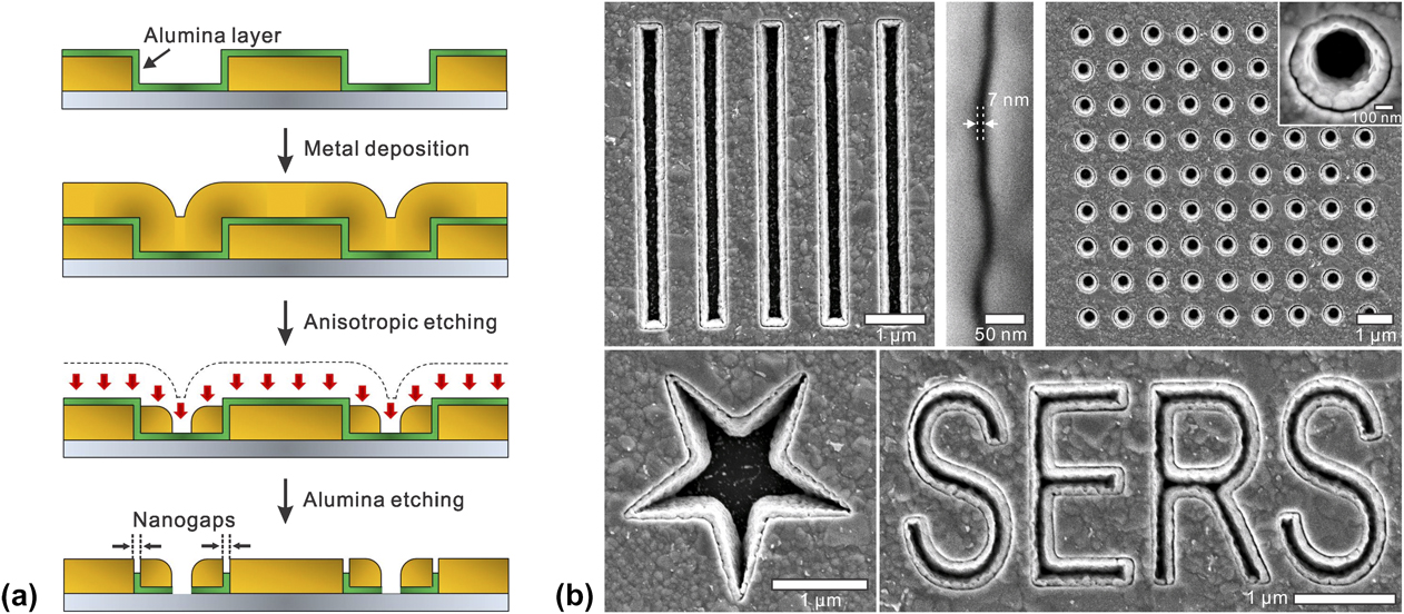
ALD can also be used in top-down lithographic patterning of metallic nanostructures. Many plasmonic devices harness ultrathin metallic gap structures to squeeze electromagnetic energy for SERS and nonlinear optics.Reference Haynes, McFarland and Van Duyne54 For example, single-molecule Raman spectroscopy has been demonstrated when a Raman-active molecule is positioned within the large electromagnetic fields generated between two closely spaced metallic nanostructures, e.g., two nearly touching nanoparticles.Reference Kneipp, Wang, Kneipp, Perelman, Itzkan, Dasari and Feld55, Reference Nie and Emory56 It is extremely challenging, however, to make ultrathin nanogaps via top-down fabrication methods such as electron beam or FIB lithography. On the other hand, ALD can control the deposited film thickness with sub-nanometer-scale resolution. It is thus desirable to create a processing scheme wherein the film thickness can be converted into the critical device dimension. This can be accomplished by growing conformal ALD films on the vertical sidewalls of patterned structures followed by deposition and anisotropic etching of another metal layer,Reference Im, Bantz, Lindquist, Haynes and Oh57 as illustrated in Fig. 5(a). In this way, various shapes and sizes of metal–insulator–metal nanogap structures can be made as shown in Fig. 5(b), while the film thickness of ALD layer itself precisely defines the size of the vertically oriented nanogap.
(a) Fabrication process schematic of the nanogap array using ALD. Starting from metallic patterns, the secondary metal layer is separated from prepatterned metallic structures by a thin Al2O3 spacer. The nanogap size is determined by the thickness of the alumina layer. (b) Scanning electron microscope (SEM) images of various shapes of nanogap structures. Adapted from Im et al.Reference Im, Bantz, Lindquist, Haynes and Oh57

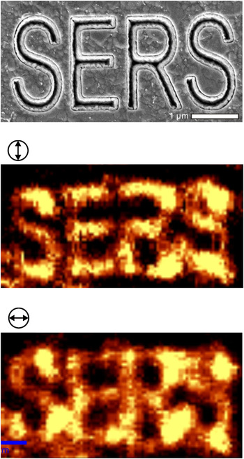
A key advantage of this scheme is that a dense array can be made over an entire wafer and that it is straightforward to couple light into and out of the nanogaps. Vertically oriented nanogap structuresReference Im, Bantz, Lindquist, Haynes and Oh57 have been utilized in SERS as shown in Fig. 6. It was shown that decreasing the gap size from 20 to 5 nm correlated to an increase in the Raman enhancement factor.Reference Im, Bantz, Lindquist, Haynes and Oh57 Furthermore, it is possible to push the limits of this scheme to define gap sizes below 1 nm, which cannot be accomplished using other top-down fabrication techniques. High-throughput fabrication of atomic-scale gaps in metal films will provide new tools for basic research as well as practical applications in sensing, spectroscopy, nonlinear optics, and optical trapping.
Confocal Raman imaging of nanogap structures formed along a surface-enhanced Raman spectroscopy (SERS) character pattern, showing the modulation of SERS hotspots along the polarization directions of an incident laser beam.

III. ALD FOR NANOBIOTECHNOLOGY
Coating nanostructures with various materials via ALD can offer a number of advantages for surface modification, biocompatibility, and biosensing. To design a successful biosensor, the sensor surface should be amenable to straightforward surface modification chemistry and be compatible with biological molecules. Although some metals, like Au, are biologically inert and can be easily modified via self-assembled monolayers (SAMs), Ag or Cu suffers from poor biocompatibility. ALD layers, even on inert surfaces, are particularly useful for biological applications, allowing specialized surface functionalization such as lipid bilayer membranes.
A. ALD-grown silica shells for biosensing
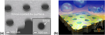
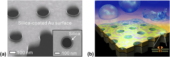
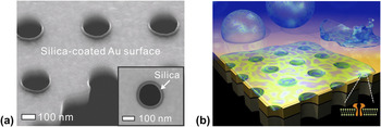
Gordon et al. developed an ALD process to deposit an extremely conformal SiO2 film with a small amount of impurities (Al2O3).Reference Hausmann, Becker, Wang and Gordon58 A key advantage of this process is its superb conformality and a relatively low growth temperature (∼250 °C). SiO2 surfaces are hydrophilic, biocompatible, and easily modified using well-established silane chemistry. For example, ALD-grown SiO2 was used to coat suspended Au nanopore arrays to support pore-spanning lipid bilayersReference Im, Wittenberg, Lesuffleur, Lindquist and Oh59 as shown in Fig. 7.
(a) Cross-sectional SEM image of nanopores uniformly coated with a 20-nm-thick SiO2 layer to promote lipid bilayer formation. (b) A schematic of a free-standing metallic nanopore array for sensing in a pore-spanning lipid bilayer environment. Adapted from Im et al.Reference Im, Wittenberg, Lesuffleur, Lindquist and Oh59
The motivation for creating suspended nanopores is to create a sensor that can be surrounded with a liquid buffer and that is more compatible with transmembrane proteins. The interaction of transmembrane proteins with underlying substrates can cause denaturation, changing the conformation of binding sites and complicating binding kinetic assays. In the suspended system, however, the planar lipid bilayer spans the pores and results in free-standing lipid bilayers that can efficiently incorporate transmembrane proteins.
Recently, free-standing nanopore arrays made in a thin Au/Si3N4 membrane were used for SPR biosensing with membrane proteins. There, the nanopore array was conformally coated with 20-nm-thick SiO2 by ALD (Fig. 7).Reference Im, Wittenberg, Lesuffleur, Lindquist and Oh59 It was shown that the SiO2 layer on the nanopore array did not significantly reduce SPR sensitivity. Most importantly, the presence of SiO2 can induce the rupture of phospholipid vesicles to form planar lipid bilayers.Reference Keller and Kasemo60 Vesicles, also known as liposomes, are spherical lipid bilayers with adjustable dimensions (typical diameter: 50 nm–1 μm) depending on the preparation method used. When a SiO2 surface is exposed to a suspension of vesicles in solution, the vesicles will adsorb on the surface. When a critical surface population is reached, the vesicles begin to rupture forming a planar lipid bilayer on the SiO2 surface.Reference Anderson, Min, Weirich, Zeng, Fygenson and Israelachvili61 A PDMS microfluidic chip was attached to the SiO2-coated nanopores for delivery of vesicles and reagents to the sensing area. By monitoring the spectral shift due to molecular binding as a function of time, it is possible to assess the binding kinetics and affinities of molecules to surface-bound targets. Real-time SPR sensing was performed using this platform and the transmembrane protein α-hemolysin (α-HL). The α-HL molecules selectively localized to the pore-spanning regions of the lipid bilayer, and SPR sensing was used to evaluate binding of an antibody to α-HL. The binding constants obtained with the method compared favorably with values obtained with alternative techniques.
Wittenberg et al.Reference Wittenberg, Im, Johnson, Xu, Warrington, Rodriguez and Oh62 has demonstrated ALD coatings on silicon microwell and nanowell arrays to facilitate the assembly of biomembrane arrays. Because phospholipid vesicles will not rupture to form supported lipid bilayers on Al2O3 surfaces,Reference Mager, Almquist and Melosh63 vesicles and natural membrane particles can be arrayed without additional chemical modification of the substrate; nor do the natural membrane particles have to be modified in any way. These arrays were used for sensing interactions between proteins and lipid-based receptors in natural cell membranes. This strategy also enabled the formation of arrays of natural membranes in nanohole arrays in Au films, which allowed the use of SPR to detect antibody binding to cell-specific membrane receptors.
B. ALD to enhance analyte adsorption
To alter surface chemistry of metals while maintaining SERS activity requires thin molecular layers, like SAMs, or a thin layer deposition technique such as ALD. In one such example, Van Duyne et al. used ALD Al2O3 on Ag nanostructures to improve SERS detection of a biomarker for anthrax spores, calcium dipicolinate (CaDPA).Reference Zhang, Zhao, Whitney, Elam and Van Duyne50 In this work, they found that more CaDPA molecules adsorb to thin Al2O3 overlayers than adsorb to bare Ag nanostructures, which lowers the limit of detection (in terms of number of anthrax spores) from 2.6 × 10³ to 1.4 × 10³ spores. In addition, in competitive adsorption experiments, it was found that CaDPA adsorbs to Al2O3 more strongly than structurally related molecules. This study also showed that Al2O3 overlayers can protect SERS substrates with no appreciably decline in performance after 9 months of storage in ambient conditions. This suggests that ALD coating of SERS substrates can make them more robust and suitable for long-term deployment and in-the-field analyses.
IV. CONCLUSION AND OUTLOOK
ALD has been a viable and widely utilized manufacturing method in the microelectronics industry. Currently, many research laboratories have access to reliable ALD tools, and the materials and processing options for ALD continue to expand. The growing field of plasmonics will increase the demand for new ALD processes to decorate various metallic surfaces at low temperatures. For the most part, existing applications in plasmonics and biotechnology have utilized Al2O3 or SiO2. In particular, metallic nanostructures that are overcoated with SiO2 shells can easily incorporate lipid bilayer membranes, which can be very useful for applications in biomimetic sensing and membrane proteins research. Other materials such as HfO2 or TiO2,Reference Frank, Wilk, Starodub, Gustafsson, Garfunkel, Chabal, Grazul and Muller64, Reference Standridge, Schatz and Hupp65 which have higher refractive indices, could also be used. Although ALD for metals also looks promising for applications in plasmonics, impurities derived from the precursors remain in the metal. Thus metal films deposited by ALD exhibit poorer electrical and optical properties compared with pure metals deposited by evaporation or sputtering. As summarized in previous sections, the requirements for coating, patterning, tuning, and protecting metallic nanostructures are indeed very demanding. Metal surfaces, which are often rough and chemically unstable, should be modified at low temperatures with ultrathin, pinhole-free overlayers. Conformal filling or complete encapsulation is required for nanostructures with extremely demanding aspect ratios. Finally, these ultrathin films should act as a robust protection layer against harsh environments. ALD can readily satisfy all of these requirements and will continue to enable new and exciting applications.
ACKNOWLEDGMENTS
This work was supported by grants to S-H. Oh from the Office of Naval Research (ONR Young Investigator Program), the National Science Foundation (NSF CAREER Award, CBET 1067681, DBI 0964216, and DMR 0941537), the National Institutes of Health (NIH R01 GM092993), and a Defense Advanced Research Projects Agency (DARPA) Young Faculty Award.