I. INTRODUCTION
Grain refinement is an effective approach to simultaneously improve both the strength and toughness of materials. Therefore, ultrafine-grained (UFG) materials have been widely investigated. As reported in previous research, in addition to optimizing the mechanical properties of a material, grain refinement has also been shown to greatly influence phase transformations. Recent studies have indicated that reverse transformation from ferrite [body-centered cubic (bcc)] to austenite (face-centered cubic) occurred at room temperature during the severe plastic deformation of a pearlitic steel, resulting in a nanocrystalline structure.Reference Ivanisenko, MacLaren, Sauvage, Valiev and Fecht 1 The martensitic transformation initiation temperature (M s) was lowered significantly with the reduction of the austenite grain size of a Fe–28.5 at.% Ni alloy.Reference Kitahara, Tsuji and Minamino 2 In Ti–Ni-based alloys, the critical austenite grain size for martensitic transformation was 50 nm, below which martensitic transformation did not occur.Reference Waitz and Karnthaler 3 When grain size was less than 100 nm, a transformation from hexagonal ω phase to bcc β phase was observed in a Ti–36Nb–2.2Ta–3.7Zr–0.3O alloy during low-pressure severe plastic deformation at room temperature.Reference Wang, Zhao, Lian, Liao, Valiev, Ringer, Zhu and Lavernia 4 Approximately 1.0 at.% carbon could be dissolved in nanocrystalline ferrite, which was much higher than the balance solubility (0.021 wt%) in the ferrite with a normal grain size.Reference Ohsaki, Hono, Hidaka and Takaki 5 Our previous study revealed that nanometer-sized granular cementite on ferrite matrix was formed in the eutectoid transformation of a UFG steel, which was prepared by ball milling and sparking plasma sintering.Reference Liu, He, Peng and Lian 6 All these experiments indicate that the phase transformation laws are indeed different in UFG compared to coarse- or medium-grained materials. Therefore, it is necessary to closely examine the phase transformation under UFG conditions. Martensitic transformations in UFG materials have been researched more commonly,Reference Kitahara, Tsuji and Minamino 2 , Reference Waitz and Karnthaler 3 , Reference Rajasekhara and Ferreira 7 – Reference Waitz, Kazykhanov and Karnthaler 9 but very little research has been reported on diffusive transformations. The difficulty is that the UFG material is very easy to coarsen in the heating process, and it is difficult to observe the UFG effect on diffusive transformations. Therefore, a UFG hypereutectoid steel was chosen as our research object, and pearlitic transformation was studied.
In our previous experiment, the ball milling and sintering method was adopted to refine grains.Reference Liu, He, Peng and Lian 6 However, this method was complicated, and it was difficult to make a large-sized specimen. Therefore, the warm rolling and annealing technique, which has been used to produce ultrafine grains in plain low and medium carbon steels in industry,Reference Song, Ponge, Raabe and Kaspar 10 – Reference Murty, Torizuka, Nagai, Kitai and Kogo 13 was adopted for grain refinement in this experiment.
Until now, the published papers on phase transformations in UFG steels primarily involved alloys or deformation effects in the process of refining grains.Reference Dong and Sun 14 – Reference Ahmad, Sarwar, Manzoor and Hussain 19 However, these two methods may influence the phase transformations. Therefore, plain hypereutectoid steel was used, eliminating the effects of alloy elements.To avoid the deformation effect on phase transformation, the UFG steel was reheated to the γ + Fe3C two-phase region, where the nondissolved carbides could prevent grains from quickly increasing in size. They were then held for different times at the elevated temperature and cooled in air. The transformation products and the corresponding average grain sizes were recorded. By performing these experiments, we observed a new pearlitic transformation phenomenon found in the UFG steel, which is related to the controlled rolling technology.
II. EXPERIMENTAL
A. Preparation of UFG steel
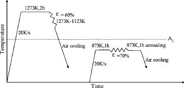
The chemical composition of the steel was the following (wt%): C, 0.98; Si, ≤0.35; Mn, ≤0.40; P, ≤0.035; and S, ≤0.030. An initial bar with the dimensions of 40 × 70 × 100 mm (thickness × width × length) was adopted for controlled rolling in the thickness direction. The rolling route is shown in Fig. 1. The specimen was heated to 1273 K and held for 2 h to homogenize the chemical composition of the austenite and then rolled to the thickness of 16 mm in the following reduction sequence in the temperature range of 1273–1123 K: 40 → 32 → 24 → 16 mm. The specimen was finally cooled in air to room temperature. A multipass warm rolling process with a total reduction of 70% was followed after the plate was reheated to 873 K and held for 1 h. The final rolled plate was then annealed at 873 K for 1 h and cooled in air to room temperature.
The schematic representation of the rolling route.

B. Heat treatment of the UFG steel
The UFG specimens with dimensions of 4 × 10 × 10 mm were heated at 1023 K for different times (5.5, 6, 6.5, 7, 7.5, 8, 8.5, and 9 min) in an electric furnace and then cooled in air for the pearlitic transformation. The microstructures were observed by optical microscopy, scanning electron microscopy, and transmission electron microscopy (TEM). To determinate if the specimen was completely austenitized after a certain heating time, another group of specimens was cooled in water after heating at 1023 K for the same times. The Rockwell hardness (HRC) of the specimens cooled in water was measured.
C. Grain boundary etching procedure
The grain boundaries of the specimens cooled in air were etched. As the heating time increased, the grain size gradually increased. The grain boundary was hard to etch because no precipitation was observed along the grain boundaries in the phase transformation, and this condition was further exacerbated by the UFG effect. Several common chemical etching methods for disclosing grains were tried: alcohol solution containing 4 wt% of nitric acid, picric acid–alcohol solution, and boiling sodium picrate solution. However, they all proved unsuccessful for grain boundary corrosion in our experiments. Therefore, the electrochemical etching method was used. This method is often used to evaluate the susceptibility to intergranular corrosion in stainless steels and alloys.Reference Aquino, Della Rovere and Kuri 20 – Reference Tan, Jiang, Deng, Gao and Li 23 The difference between the intragranular and intergranular corrosion potentials should supply the driving force for grain boundary corrosion.
The specimens were ground with SiC sandpapers from grade #320 to #2000, polished with 1-μm diamond particles, and then rinsed in distilled water before the etching.
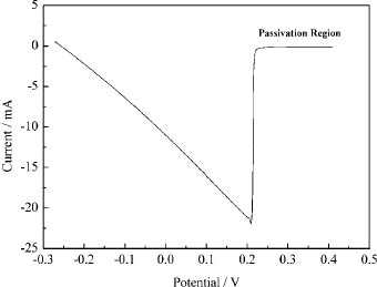
A three-electrode system was utilized. The working electrode was constructed with the specimen embedded in epoxy resin with an exposure area of 1 cm2. A graphite rod and a saturated calomel electrode were used as a counter electrode and a reference electrode, respectively. Saturated picric acid with 3 wt% NaNO3 was used as the electrolyte. The anodic polarization curve is shown in Fig. 2 (using a specimen heating time of 7 min and cooling in air, for example). The open-circuit potential was −0.27 V. The specimen was scanned in an anodic direction at a rate of 0.01 V/s and stopped in the passivation region, which had a constant current at nearly 0 A. All the electrochemical measurements were carried out using a CHI650C (ChenHua, Inc., Shanghai, China) electrochemical workstation.
The anodic polarization curve of the electrochemical etching process.

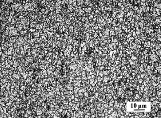
Figure 3 shows the grains etched by the electrochemical method, in which the grains resulting from the electrochemical method are clearly observed.
The grains of the specimen cooling in air after heating for 7 min at 1023 K.

D. Determination of transformation temperatures
The thermal dilatation method was used to measure the transformation temperatures of the specimens with different grain sizes. The rolled specimens, which were machined into the dimensions of Φ 6 × 10 mm, were heated to 1023 K at 10 K/s and held for 1 or 10 min. The radial dilatation–temperature curves were determined during the air cooling process. The whole process was conducted in a Gleeble 1500 thermal simulator (Dynamic Systems, Inc., TX).
III. RESULTS
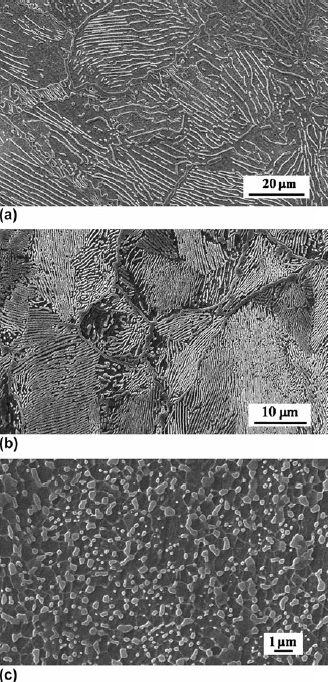
As shown in Fig. 4(a), the microstructure of the steel before rolling consists of lamellar pearlite and a continuous network of carbides. The average grain size is approximately 73 μm. The microstructure after rolling at 1273–1123 K is shown in Fig. 4(b). Both the lamellar spacing of the pearlite and the grain size become smaller, and the average grain size is approximately 31 μm. The microstructure of the steel after multipass warm rolling and subsequent annealing at 873 K is shown in Fig. 4(c). Dispersed granular cementite of different sizes forms on the ferrite matrix by fragmentation of the lamellar pearlite during rolling. The grain size is approximately 1 μm. Thus, UFG hypereutectoid steels are successfully prepared by the technique of warm rolling and annealing.
The microstructures of the specimens before rolling (a), after rolling at 1273–1123 K (b) and after warm rolling and annealing (c).

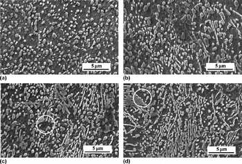
Pearlitic transformation of the UFG steel is conducted by reheating the UFG samples at 1023 K for different times and then cooling in air. The microstructures of the specimens are shown in Fig. 5. Granular cementite on ferrite matrix is observed at a lower heating time [Fig. 5(a)], and lamellar pearlite formed gradually only after heating time longer than 7 min [Figs. 5(b)–5(d)].
The microstructures of the specimens cooling in air after heating at 1023 K for different time [7 (a), 7.5 (b), 8 (c), and 8.5 min (d)].

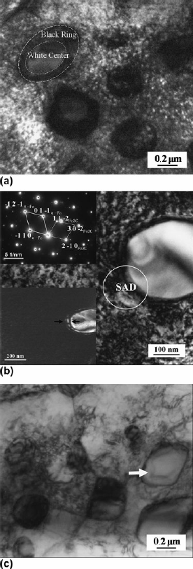
The specimen shown in Fig. 5(a) was further observed by TEM, as shown in Fig. 6. Figure 6(a) shows the granular carbides on the ferrite matrix, and some of the carbides have a white center and a “black ring.” Such carbides were further observed with selected area diffraction (SAD) and dark field imaging, as shown in Fig. 6(b). The SAD under the zone axis [1 1 1]a-Fe//[2 4 3]Fe3C is shown in the insert on the top left corner, and the ferrite and cementite spots are indexed. The dark field image of the spot (1 1)Fe3C is shown in the other insert on the bottom left corner. An incomplete transformation layer of cementite, marked by two arrows, can be observed surrounding the central granular carbide, where cementite can be observed discontinuously. This region corresponds to the “black ring” in the bright field image. It is the transition layer to the newly formed cementite, through which we can conclude that new cementite grows up by attaching to the central granular carbides that are the nondissolved or proeutectoid carbides. When the structure transition of these “black rings” is completed, they become a white color as shown with the arrow in Fig. 6(c). Finally, the integrated granular carbide forms.
The TEM images of the specimen cooling in air after heating for 7 min.

One question is raised: why is lamellar pearlite only observed at heating times longer than 7 min? Two reasons are possible. One is that when the heating time is less than 7 min, samples have not been completely austenitized. Thus, ferrite with granular cementite is the initial rolling structure. The other possible reason is that the austenitization of the specimens was completed during the shorter heating time but the formation of traditional lamellar pearlite was inhibited. Instead, ferrite and cementite grow from the austenite in a noncooperative manner, producing an array of cementite particles in the ferrite matrix. Some cementite can be observed to form by attaching to the nondissolved or proeutectoid carbides. These are the typical properties of divorced eutectoid (DET).
To answer the question above, we must determine the critical heating time of complete austenitization.
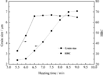
Another group of UFG samples was cooled in water after heating at 1023 K for the same times. The hardness of them was measured. The results are shown in Fig. 7. The HRC gradually increases with the heating time and then reaches a stable value at heating times greater than 6.5 min, indicating that the samples have already finished austenitizing at this heating time. The austenitizing condition of the specimen cooling in air and water should consistent after being heated for the same length of time. Therefore, specimen that cooled in air after heating for 6.5 min had already been completely austenitized, which supports the second reason above. When the heating time is 6.5 or 7 min, no lamellar pearlite is generated, and pearlitic transformation is in the form of DET. Traditional pearlitic transformation was altered by shortening the holding time after complete austenitization.
The grain size variation of the specimens cooling in air and the HRC variation of the specimens cooling in water.

Meanwhile, as the austenitizing time progresses, grains quickly grow up. The change in the average grain size is shown in Fig. 7. The grain size shows an approximately linear increase from heating times of 6 to 8 min. According to the microstructures in Fig. 5 and the grain size curve in Fig. 7, the formation of lamellar pearlite is inhibited and only DET occurs with a small grain size. A critical value of approximately 4 μm, corresponding to the heating time 7 min, is observed. When the average grain size is larger than this value, lamellar pearlite is gradually produced. When grain size is smaller than this value, the pearlitic transformation occurs in the form of DET.
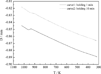
The transformation temperatures of specimens with different grain size were determined by the thermal dilatation method. As the rolling specimen is held at 1023 K for 1 min and cooled in air to room temperature, the grain size is measured to be approximately 3–4 μm. The microstructure consists of cementite particles and ferrite matrix, which appear almost the same as that in Fig. 5(a). The transformation temperature range (TTR) of this specimen is 963–933 K and the corresponding undercooling temperature ΔT is 37 K, which was determined by the radial dilatation–temperature curve shown in curve 1 of Fig. 8. With a holding time of 10 min, the grain size is approximately 7–8 μm. Lamellar pearlite can be observed in the micrograph, and the microstructure is almost the same as that in Fig. 5(d). TTR is 948–898 K and ΔT is 52 K, which is shown in curve 2 of Fig. 8. The undercooling in fine-grained steel is approximately 15 K lower than that in coarse-grained steel, and this is mostly consistent with the undercooling difference between traditional DET and lamellar pearlitic transformation.Reference Verhoeven and Gibson 24
The dilatation-temperature curves of the specimens cooling in air after holding at 1023 K for different times (1 and 10 min).

DET has been widely investigated in high carbon steelsReference Oyama, Sherby, Wadsworth and Walser 25 – Reference Taleff, Syn, Lesuer and Sherby 27 and has proven to be very effective in promoting the formation of spheroidized cementite in industry. As established in the literature,Reference Verhoeven and Gibson 24 , Reference Payson, Hodapp and Leeder 28 , Reference Verhoeven 29 with the same carbon content in normal grain size steel, DET occurs only at temperatures immediately below A 1and is replaced by lamellar pearlitic transformation at lower temperatures. Therefore, DET easily occurs at slower cooling rates and lower undercooling. This is in contrast to lamellar pearlitic transformation, which has a higher cooling rate and undercooling. As shown in our experiment above, with the same carbon content and cooling rate, lamellar pearlitic transformation can occur in steel with normal grain sizes. However, only DET is observed when the grain size is smaller than a critical value. Thus, it is clear that refining the grains promotes DET.
This result is similar to our previous experiment in which a critical grain size, at approximately 4 μm, is observed in order for lamellar pearlite to form in a 1.32 wt% carbon steel produced by ball milling and spark plasma sintering.Reference Liu, He, Peng and Lian 6 One difference is that the reheating temperature is 1173 K for the sintered specimen. At the beginning of this experiment, the reheating temperature was also chosen to be 1173 K for comparison. However, grains grew so quickly that we could not even control the grain size. Thereafter, we gradually lowered the reheating temperature to 1023 K. The grain coarsening rates of these two steels are different. It is much slower for the ball milling and sintered specimen, which has not been obviously coarsened even when reheated at 1173 K for 5 min. This result indicates that the grains refined by mechanical rolling have a strong constituent inheritance to the original coarse grains, such as lattice orientations, structures, and defects. Therefore, the grains are easily coarsened by the motion of the grain boundaries when reheated.
IV. DISCUSSION
The abnormal pearlitic transformation is related to the variation of carbon diffusion in the UFG steel.
A. The effect of UFG on carbon diffusion rate
The carbon atom is a typical interstitial atom in steel. The grain boundary and bulk diffusion of interstitial atoms have been researched previouslyReference Tong, Tao, Wang, Lu and Lu 30 – Reference Christien, Le Gall and Saindrenan 32 ; however, data on carbon atom diffusion in steels are scarce. Therefore, the grain boundary and bulk diffusion coefficients (D gb and D v) of several similar interstitial atoms are shown in Table I.
The grain boundary and bulk diffusion coefficients of different interstitial atoms.

According to Table I, within the temperature range 900–960 K (the temperatures at which phase transformation occurs in our experiment), we calculate that D gb is approximately several orders of magnitude larger than D v(N diffusion in α-Fe is about 2 orders of magnitude larger, C diffusion in Nb is also 2 orders of magnitude larger, and P diffusion in martensite is 10 orders of magnitude larger). The diffusion of carbon atoms in steel (which are typical diffusing interstitial atoms) must show similar behavior. Therefore, we conclude that the grain boundary diffusion of carbon atoms is much larger than bulk diffusion in the temperature range from 900 to 960 K. As the grains become finer, the total amount of the grain boundaries increases, and the diffusion rate of carbon atoms in steel increases.
B. The effect of UFG on the carbon gradient and the diffusion distance from grain boundaries to nondissolved cementite
The diffusion conditions of carbon atoms in austenite for a hypereutectoid steel possessing a granular cementite and ferrite matrix microstructure under conditions of heating in the γ + Fe3C two-phase region are discussed below.
During the initial stages of austenitization, nondissolved cementites (NCs) are uniformly distributed in an austenite matrix and spheroidized automatically to decrease the surface energy during heating. According to the Gibbs–Thomson formula, the relationship between the carbon composition in the austenite around the NC and the radius of this NC is shown in Eq. (1) [Refs. Reference Ostwald33 and Reference Liu, Ren and Wang34]:
 $${\rm ln}{{C_{{\rm{\gamma }}(r)} } \over {C_{{\rm{\gamma }}(\infty )} }}\, = \,{{2{\rm{\beta }}V_{{\rm{Fe3C}}} } \over {kTr}}\quad,$$
where C γ(r) and C γ(∞) are the carbon compositions in the austenite around the NCs, which have radii r and ∞, respectively. β is the interfacial energy between the austenite and cementite. V Fe3C is the molar volume of cementite. Equation (1) shows that the carbon composition in the austenite around the NC C γ(r) is inversely proportional to the radius of this NC r.
Meanwhile, it has been proved by the Greenwood model thatReference Greenwood 35 :
 $$C_{{\rm{\gamma }}_{{\rm{ave}}} } \, = \,C_{\rm{\gamma }} (\bar r)\quad,$$
where
 $C_{{\rm{\gamma }}_{{\rm{ave}}} } $
is the average carbon composition of austenite,
 $\bar r$
is the average radius of NCs, and
 $C_{{\rm{\gamma }}(\bar r)} $
is the carbon composition in the austenite around the NC having a radius
 $\bar r$
.
Therefore, according to Eq. (1), if the radius of a NC is greater than the average radius (
 $R > \bar r$
), then:
 $$C_{\rm{\gamma }} (R)\, \,\lt \,\,C_{\rm{\gamma }} (\bar r)\quad.$$
Combining Eq. (2) with Eq. (3), we obtain:
 $$C_{\rm{\gamma }} (R)\, \lt \,C_{{\rm{\gamma }}_{{\rm{ave}}} }\quad .$$
Equation (4) shows that the carbon composition in the austenite around the NC having a radius larger than
 $\bar r$
is lower than the average composition of austenite. Meanwhile, during the growth of austenite grains throughout heating, the carbon composition in the grain boundary must be higher than the intragranular composition for carbon migration, so we know that:
 $$C_{{\rm{\gamma }}_{{\rm{ave}}} } \, \lt \,\,C_{\rm{\gamma }}^{{\rm{bou}}}\quad ,$$
where C γ bouis the carbon composition on austenite grain boundary.
According to Eqs. (4) and (5), we obtain:
 $$C_{\rm{\gamma }} (R)\, \lt \,C_{\rm{\gamma }}^{{\rm{bou}}} \quad.$$
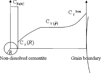
Equation (6) shows that there is a carbon composition gradient in the austenite between the NC, which has a radius R larger than
 $\bar r$
and the grain boundary. The carbon composition gradient is shown in Fig. 9.
The carbon composition gradient between a large NC in the grain and grain boundary.

In the carbon composition gradient, carbon atoms tend to diffuse from austenite and grain boundaries to the NC, which has a large radius during heating and the subsequent air cooling process. However, the diffusion conditions of carbon atoms are different in coarse-grained and UFG steels.
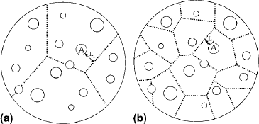
Figure 10 shows two austenite regions of equal area in two coarse-grained and UFG steels. The circles represent the NCs at different radii and the dotted lines represent the grain boundaries. The NCs are uniformly distributed in the austenite. Regarding the cementite (A), which has a radius larger than
 $\bar r$
, the minimum distance between (A) and the grain boundary is L
1 in Fig. 10(a). However, in Fig. 10(b), it becomes L
2, which is much shorter than L
1. It is obvious that the minimum distance between the large NC and the austenite grain boundary greatly decreases as the grains become finer in size.
Two schematic diagrams showing that the NCs of different sizes are uniformly distributed in coarse grains (a) and ultrafine grains (b).

When the coarse-grained steel is cooled in air, longer distances reduce the amount of carbon atoms that diffuse from the grain boundary to the NC surroundings. However, as the distance is shortened because of the UFG effect, the carbon atoms easily diffuse to the NC surroundings.
The NCs on the grain boundaries are considered separately. Some NCs are distributed on the grain boundaries [shown in Fig. 10(b)], which can suppress the coarsening of UFG to some degree during heating. Carbon atoms can diffuse to these NCs along grain boundaries directly, and this promotes new cementite growth by attaching to these carbides on the grain boundaries. The number of the NCs on the grain boundaries is less than that within the grains, and the transformation and diffusion inside the grains are regulated factors.
As described above, accelerated carbon diffusion to the NC surroundings promotes new cementite growth by attaching to the nondissolved or proeutectoid carbides. Meanwhile, as the number of grain boundaries increases, more rapid diffusion paths are provided. Therefore, the carbon depletion in austenite is also accelerated, promoting ferrite growth. Finally, cementite particles on the ferrite matrix are obtained. This conclusion can also be proved by considering the change in undercooling temperatures; as shown in Fig. 8, lower undercooling is needed in the fine-grained specimen, which indicates that ferrite is formed more easily.
C. UFG effect on the growth of lamellar pearlite
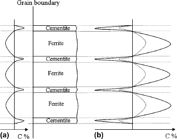
Because the carbon atoms on some regions of a grain boundary have the shortest distance to a NC in the grain, they will diffuse faster to this surrounding NC. The carbon content in this part of a boundary will be lower than that in other parts. In this case, a series of carbon content fluctuations are generated on grain boundaries, promoting the nucleation of pearlite on boundaries, as shown by the model in Fig. 11(a). In Figs. 5(c) and 5(d), when the grain size increases to 6–8 μm, the regions in circles show the pearlite nucleating on the grain boundaries, which verifies the model proposed here.
(a) The carbon fluctuations on the grain boundary before the nucleation of pearlite. (b) The carbon gradient in the austenite before pearlite growth frontier. Solid line shows the gradient in coarse-grained sample and dotted line shows the weakened gradient in the UFG sample.

During the growth of normal lamellar pearlite, a carbon gradient in the austenite before pearlite growth frontier is necessary, which is shown with a solid line in Fig. 11(b). Carbon content in the austenite before the ferrite growth frontier is higher than that before the cementite. Therefore, the carbon atoms in austenite will diffuse from the ferrite frontier to the cementite frontier, providing a concentration gradient for the growth of lamellar pearlite. However, in the UFG sample, the diffusion rate of carbon atoms increases. The carbon gradient is weakened, as shown by the dotted line in Fig. 11(b). When the weakened gradient cannot meet the necessary concentration conditions for the growth of lamellar pearlite, the formation of normal lamellar pearlite is inhibited.
As discussed before, the accelerated diffusion and the shortening diffusion distance of carbon atoms promote DET. These conditions restrict the formation of normal lamellar pearlite in UFG steel. Granular cementite is finally observed in pearlitic transformation.
V. CONCLUSIONS
-
(i) A UFG hypereutectoid steel was prepared by a warm rolling and annealing technique. The grain size is approximately 1 μm, and the microstructure consists of granular cementite and ferrite.
-
(ii) An electrochemical etching method was developed to disclose the grain boundaries of the UFG hypereutectoid steel. The grain size of the UFG steel linearly increases with prolonged heating at the beginning stage of austenitization.
-
(iii) Grain size has a great influence on the pearlitic transformation in plain hypereutectoid steel. There is a critical grain dimension at approximately 4 μm. When the grain size is smaller than this value, pearlitic transformation occurs in the form of DET and the microstructure is a ferrite matrix with granular carbides. When the grain size is larger than this value, lamellar pearlite gradually forms with the growth of grains.
ACKNOWLEDGMENTS
The authors are grateful for financial support from China National Science Foundation in Grant Nos. 50871082 and 51271137.