


1. Introduction
During the coal mining process, inevitable internal damage to the rock mass and redistribution of the in -situ stress can lead to engineering issues such as rock collapse, cracking, and rock bursts. Therefore, it is necessary to conduct borehole detection or geological surveys inside the mine holes, which is crucial in preventing industrial accidents and protecting the environment [Reference Fan and Liu1–Reference Ori and Zarrouk6]. Conventional robots available on the market face challenges such as inapplicability to small-diameter and variable-diameter mine holes and weak crawling capabilities. Therefore, the development of a novel mine hole robot capable of operating in small-diameter mine holes with steep slopes is significant for the advancement of mobile carriers that enable high-quality inspections.
Researchers have designed various pipeline robots with different structures and principles to address the challenges posed by complex pipeline environments with small and variable diameters [Reference Moriyama7–Reference Cardona, Cerrato and García15]. Mishra et al. developed a fluid-driven pipeline inspection robot, which operates without the need for external power and utilizes the force difference of the conveying medium for motion. This robot is primarily suitable for pipelines used in liquid transportation [Reference Mishra, Agrawal, Abbas, Srivastava and Yadav16]. Valls Miro et al. and Gangfeng Liu et al. designed pipeline robots based on omnidirectional movement using Mecanum wheels. These robots overcome the limitations of fluid-driven robots and can move longitudinally and circumferentially, making them suitable for pipelines with constant diameters [Reference Valls Miro, Ulapane, Shi, Hunt and Behrens17, Reference Liu, Mo, Li, Li and Li18]. Takemori et al. designed a wheelless snake-like robot capable of flexible movement and traversing pipelines with irregular cross-sections and varying diameters [Reference Takemori, Tanaka and Matsuno19]. Virgala et al. developed an articulated snake-like robot, investigating the influence of different pipeline surfaces on its motion and stability when moving on inclined surfaces. This study provided a control solution for the movement of snake-like robots in complex environments [Reference Virgala, Kelemen, Boek, Bobovský, Hagara, Prada, Oščádal and Varga20]. Kakogawa et al. designed a multi-link articulated wheel-type pipeline robot that achieves spiral movement by twisting its body shape within the pipeline. This robot exhibits stable movement and is easy to control [Reference Kakogawa, Oka and Ma21]. Guo et al. and Gangfeng Liu et al. also designed multi-link articulated wheel-type robots for internal pipeline inspection, demonstrating good adaptability to small and complex pipelines [Reference Guo, Yuan, Bao, Yuan, Ma and Du22, Reference Gao, Huang, Tang, Lang and Gao23]. The stability of snake-like and hinged robots’ motion is influenced by the smoothness of the pipeline surface, movement speed, and pipeline inclination. These robots are suitable for pipelines with small slopes and constant diameters. Sakura et al., Lei Zhang et al., and Zheng Tao et al. designed track robots based on wall-pressing structures, which can adapt to complex pipeline environments with rough surfaces and obstacles. These robots are suitable for pipelines with larger slopes and diameters [Reference Moriyama24–Reference Zhang and Wang26]. Liu et al. developed a creeping-type pipeline robot capable of working in pipes with diameters ranging from 100 mm to 180 mm. Although it exhibits strong maneuverability, the creeping movement method affects the stability and flexibility of camera-based detection systems [Reference Liu, Dai, Wang, Bi, Song, Zhao and Li27]. Zheng Tang et al. designed a robot structure adaptable to different diameter pipelines, utilizing a shear cutter fork structure to achieve variable diameters. This robot can stably carry detection devices such as cameras and is suitable for pipelines with diameters ranging from 500 mm to 800 mm [Reference Tang, Li, Ma, Chen and Yang28]. Diyun Zheng and Gangfeng Liu et al. designed a triangular-structured robot adaptable to various pipelines, employing multiple motors for single-wheel control. This robot is suitable for small-diameter pipelines with lighter loads [Reference Zheng29, Reference Elankavi, Dinakaran, Doss, Chetty and Ramya30]. Extensive research has been conducted on pipeline robots, laying the foundation for the design of adaptive small-sized mine hole robots. However, in practical environments, mine holes differ significantly from pipeline environments. Mine holes often have variable diameters and steep slopes, and robots cannot adjust their structures to adapt to diameter changes, resulting in malfunctioning in small-diameter and variable-diameter mine holes with steep slopes.
To address the issue of robots being unable to function properly in the special environment of mine holes, this paper presents the design of an adaptive small-sized mine hole robot. First, for the small-diameter mine hole, a straight-line layout of a two-wheel wall-pressing robot is designed, which effectively minimizes the robot’s size. The robot is driven by a DC reduction motor mechanism. Second, to ensure the smooth operation of the robot in mine holes with variable diameters, this paper proposes a variable-diameter control method based on position and force estimators, which endows the robot with self-perception of external forces. By utilizing the robot’s structure to calculate the output of force sensors, the distance and force between the wheels and the hole wall are dynamically adjusted, enabling the robot to adapt its diameter by perceiving external forces. Finally, the effectiveness and robustness of the robot are validated in the simulated mine hole.
The main structure of the paper is as follows: Section 2 provides a detailed introduction to the design of the adaptive small-sized mine hole robot. Section 3 describes the model and control of adaptive variable diameter. Section 4 demonstrates the experimental testing and results of the robot based on a metal processing prototype, validating the design and model. Section 5 concludes the paper.
2. Structure design of small-sized mine hole robot
The small-sized mine hole robot adopts a two-wheel wall-pressing mode driven by a single motor. It can be categorized into three functional components: the driving mechanism, the adjusting mechanism, and the auxiliary mechanism. The driving mechanism primarily provides power for the robot’s movement. The adjusting mechanism achieves the function of automatically adapting to changes in hole diameter through the measurement unit and the end effector. The auxiliary mechanism is located at both ends of the robot and assists in maintaining the robot’s center of mass on the centerline of the mine hole during diameter changes. The system model of the small-sized mine hole robot is illustrated in Figure 1.
Robot system model diagram.

2.1. Driving mechanism
The driving mechanism is the actuator of the robot to achieve the mobile function, which consists of the gearmotor, transmission wheel legs, gears, etc., as shown in Figure 2.
Schematic diagram of mobile unit.

The two-wheel wall-pressing structure of the robot is achieved through wheel legs, in which the drive wheel leg is used to load the drive structure. This paper selects a compact and stable gear transmission consisting of bevel gears and cylindrical spur gears. The transmission structure converts the radial rotation of the motor into axial rotation through bevel gears. The bevel gear and no. 1 cylindrical spur gear, crawler wheel, and no. 4 cylindrical gear connect coaxially using the pins. The rotational force of the motor is transmitted to the crawler wheel and thus drives the rotation of the crawler wheel. Still, the direction of rotation of the two crawler wheels is different, and the driving mechanism is shown in Figure 3.
Design of driving mechanism.

2.2. Adjustment mechanism
The adjustment structure is the actuator that realizes the reducer function and consists of a stepper motor, a screw nut, and a sleeve, as shown in Figure 2. Driven by the stepper motor, the screw nut pushes the wheel leg to generate enough force between the crawler wheel and the hole wall to overcome the forward resistance, which provides the necessary conditions for the robot to move. A miniature force sensor is mounted inside the sleeve, enabling indirect force measurement between the crawler wheel and the hole wall. A spring is installed before the sensor and the screw nut to increase the flexibility of the mechanism, as shown in Figure 4.
Design of adjustment mechanism.

2.3. Auxiliary mechanism
Under the influence of gravity, the lower-side wheels of the robot are squeezed, which affects the control of the robot by the regulating mechanism. Therefore, an auxiliary structure is installed at both ends of the robot, which mainly consists of moving wheels, limit rods, telescopic springs, and swing rods. The three swing rods with a clamp angle of 120° contact the spring through a sliding ring, and the spring is compressed to achieve the contraction of the swing rods to achieve the function of centering the robot, the structure of which is shown in Figure 5.
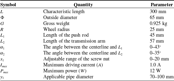
Key structural parameters of the robot.
Design of auxiliary mechanism.

3. Research on method of adaptive to changes in hole diameters
The variable-diameter control method based on position and force estimator is designed, which enables the robot to possess external force self-sensing capability and achieves the robot’s self-adaptation to changes. The process of the adaptive diameter changes is divided into two steps: actively adapting to the hole diameter and adjusting the traction force. In actively adapting to the hole diameter, small changes can be adjusted by the flexible mechanism. When the change is significant, the system adopts the variable-diameter control method to achieve auto-adaptive to the change of hole diameters. In regulating the force, the position and force estimator automatically calculate the external force to adjust the force. The dynamic position model and the mechanical model are established to analyze the position and force changes in the process of autonomously adapting to the changes. The critical structural parameters of the robot are shown in Table I.
3.1. Force and position estimator design
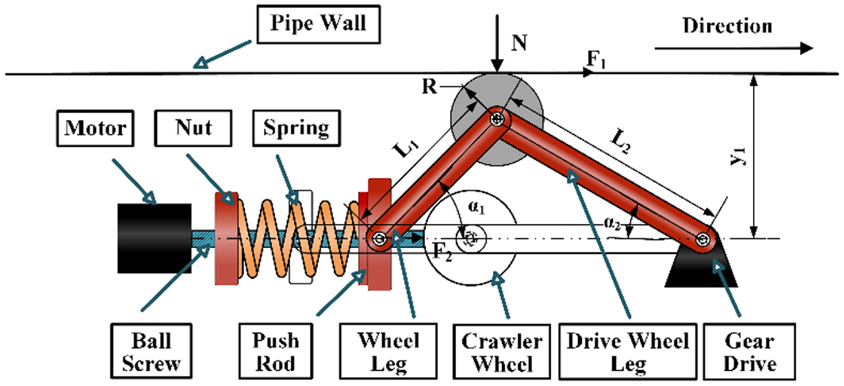
The position estimation is designed to estimate the position of the crawler wheel of the robot during the diameter-changing process. The position of the crawler wheel is only determined by the nut position, so the position of the crawler wheel can be mapped from the position of the nut through the geometric relationship. As shown in Figure 6, the dynamic transformation model of position is established, setting the position of the nut when the robot’s wheel leg is retracted into the cabin at the initial position of 0. Analyze the position change of the nut at time k. The relationship between
 $\boldsymbol{x}_{1}(\boldsymbol{k})$
and crawler wheel position
 $\boldsymbol{y}_{1}(\boldsymbol{k})$
.
Schematic diagram of geometric relationships during the adjustment process.

The geometric relationship of the robot when changing diameter is as shown in Eq. (1):
 \begin{align} \left\{\begin{array}{l} \sin \alpha\! \left(\boldsymbol{k}\right)=\frac{\boldsymbol{y}_{1}\left(\boldsymbol{k}\right)-\boldsymbol{y}_{1}\left(0\right)}{\boldsymbol{L}_{1}}=\sqrt{1-\left(\frac{\boldsymbol{L}_{1}^{2}\,+\,\boldsymbol{H}\left(\boldsymbol{k}\right)^{2}-\boldsymbol{L}_{2}^{2}}{2 \times \boldsymbol{L}_{1}\times\,\boldsymbol{H}\left(\boldsymbol{k}\right)}\right)^{2}}\\[3pt] \boldsymbol{x}_{1}\!\left(\boldsymbol{k}\right)=\boldsymbol{H}\!\left(\boldsymbol{k}-1\right)-\boldsymbol{H}\!\left(\boldsymbol{k}\right) \end{array}\right. \end{align}
From Eq. (1), we can get
 \begin{align} \left\{\begin{array}{l} \boldsymbol{y}_{1}\!\left(\boldsymbol{k}\right)=\frac{\sqrt{\boldsymbol{H}\left(\boldsymbol{k}\right)^{2}\times \left(2\times \left(\boldsymbol{L}_{1}^{2}\,+\,\boldsymbol{L}_{2}^{2}\right)-\boldsymbol{H}\left(\boldsymbol{k}\right)^{2}\right)-\left(\boldsymbol{L}_{1}^{2}-\boldsymbol{L}_{2}^{2}\right)^{2}}}{2\times \boldsymbol{H}\left(\boldsymbol{k}\right)}\\[3pt] \boldsymbol{H}\!\left(\boldsymbol{k}\right)=\boldsymbol{H}\!\left(\boldsymbol{k}-1\right)-\boldsymbol{x}_{1}\!\left(\boldsymbol{k}\right)\\[3pt] \boldsymbol{H}\!\left(0\right)=\boldsymbol{L}_{1}+\boldsymbol{L}_{2},\boldsymbol{y}\!\left(0\right)=\boldsymbol{R} \end{array}\right. \end{align}
define
 \begin{align} \left\{\begin{array}{l} \boldsymbol{k}_{1}=\boldsymbol{L}_{1}^{2}-\boldsymbol{L}_{2}^{2}\\[3pt] \boldsymbol{k}_{2}=\boldsymbol{L}_{1}^{2}+\boldsymbol{L}_{2}^{2} \end{array}\right. \end{align}
Bringing Eq. (3) into Eq. (2):
 \begin{align} \boldsymbol{H}\!\left(\boldsymbol{k}\right)=\boldsymbol{H}\!\left(\boldsymbol{k}-1\right)-\boldsymbol{x}_{1}\!\left(\boldsymbol{k}\right),\boldsymbol{H}\!\left(0\right)=\boldsymbol{L}_{1}+\boldsymbol{L}_{2} \end{align}
 \begin{align} \boldsymbol{y}_{1}\!\left(\boldsymbol{k}\right)=\frac{\sqrt{\boldsymbol{H}\!\left(\boldsymbol{k}\right)^{2}\times \left(2\times \boldsymbol{k}_{2}-\boldsymbol{H}\!\left(\boldsymbol{k}\right)^{2}\right)-\boldsymbol{k}_{1}^{2}}}{2\times \boldsymbol{H}\!\left(\boldsymbol{k}\right)}+\boldsymbol{R} \end{align}
According to Eqs. (4) and (5), it can be seen that the relationship between the position change of the nut
 $\boldsymbol{x}_{1}(\boldsymbol{k})$
and the crawling wheel position
 $\boldsymbol{y}_{1}(\boldsymbol{k})$
is nonlinear. Every change of the nut needs to update the value of
 $\boldsymbol{H}(\boldsymbol{k})$
. The input change amount
 $\boldsymbol{x}_{1}(\boldsymbol{k})$
can be positive or negative, and the direction of the crawler wheel opening is defined as positive.
When the traction force is adjusted, the robot has adapted to the hole diameter so that the crawling wheels are tightly attached to the hole wall. As shown in Figure 7, a mechanical model of one side of the robot is established to analyze the relationship between the thrust
 $\boldsymbol{T}_{\boldsymbol{d}}$
provided by the push rod and the traction force
 $\boldsymbol{F}_{1}$
. Since the dead weight of the rod is small compared to other forces, it is not considered in the calculation.
Schematic diagram of force analysis on one side of the diameter change process.
Establish equations based on geometric relationships:
 \begin{align} \begin{array}{l} \left[\begin{array}{l@{\quad}l} \boldsymbol{x} & \boldsymbol{y} \end{array}\right]=\left[\begin{array}{l@{\quad}l} \boldsymbol{L}_{1} & \boldsymbol{L}_{2} \end{array}\right]\times \left[\begin{array}{l@{\quad}l} \cos \alpha _{1} & \sin \alpha _{1}\\ \cos \alpha _{2} & 0 \end{array}\right]\\[5pt] \ \qquad \begin{array}{lll} & & =\left[\begin{array}{l@{\quad}l} \boldsymbol{L}_{1} & \boldsymbol{L}_{2} \end{array}\right]\times \left[\begin{array}{l@{\quad}l} \cos \alpha _{1} & 0\\ \cos \alpha _{2} & \sin \alpha _{2} \end{array}\right] \end{array} \end{array} \end{align}
Perform variations on both sides of Eq. (6):
 \begin{align} \begin{array}{l} \left[\begin{array}{l@{\quad}l} \boldsymbol{dx} & \boldsymbol{dy} \end{array}\right]=\left[\begin{array}{l@{\quad}l} \boldsymbol{L}_{1}\times \boldsymbol{d}\alpha _{1} & \boldsymbol{L}_{2}\times \boldsymbol{d}\alpha _{2} \end{array}\right]\times \left[\begin{array}{l@{\quad}l} \sin \alpha _{1} & \cos \alpha _{1}\\ \sin \alpha _{2} & 0 \end{array}\right]\\[5pt] \begin{array}{l@{\quad}l@{\quad}l} & \begin{array}{l@{\quad}l} & \end{array} & \quad =\left[\begin{array}{l@{\quad}l} \boldsymbol{L}_{1}\times \boldsymbol{d}\alpha _{1} & \boldsymbol{L}_{2}\times \boldsymbol{d}\alpha _{2} \end{array}\right]\times \left[\begin{array}{l@{\quad}l} \sin \alpha _{1} & 0\\ \sin \alpha _{2} & \cos \alpha _{2} \end{array}\right] \end{array} \end{array} \end{align}
Integrating Eq. (7) gives
 \begin{align} \boldsymbol{dx}=\left(\tan \alpha _{1}+\tan \alpha _{2}\right)\times \boldsymbol{dy} \end{align}
Using the trigonometric function sum of squares relationship, we get
 \begin{align} \tan \alpha _{1}+\tan \alpha _{2}=\sum _{\boldsymbol{j}=1}^{2}\frac{\left(\boldsymbol{y}_{1}\!\left(\boldsymbol{k}\right)-\boldsymbol{y}_{1}\!\left(0\right)\right)}{\sqrt{\boldsymbol{L}_{\boldsymbol{j}}^{2}-\left(\boldsymbol{y}_{1}\!\left(\boldsymbol{k}\right)-\boldsymbol{y}_{1}\!\left(0\right)\right)^{2}}} \end{align}
According to the principle of virtual work, assuming a virtual displacement, force multiplied by the virtual displacement equals virtual work, and the total virtual work is 0.
 \begin{align} \boldsymbol{N}\times \boldsymbol{dy}=\boldsymbol{F}_{2}\times \boldsymbol{dx} \end{align}
Putting Eq. (9) into Eq. (10), the relationship between the thrust
 $\boldsymbol{T}_{\boldsymbol{d}}$
and the force
 $\boldsymbol{N}$
of the one-sided wheel on the hole wall is obtained as Eq. (11):
 \begin{align} \boldsymbol{N}=\boldsymbol{T}_{\boldsymbol{d}}\times \sum _{\boldsymbol{j}=1}^{2}\frac{\left(\boldsymbol{y}_{1}\!\left(\boldsymbol{k}\right)-\boldsymbol{y}_{1}\!\left(0\right)\right)}{\sqrt{\boldsymbol{L}_{\boldsymbol{j}}^{2}-\left(\boldsymbol{y}_{1}\!\left(\boldsymbol{k}\right)-\boldsymbol{y}_{1}\!\left(0\right)\right)^{2}}} \end{align}
According to the kinetic friction formula, we can get
 \begin{align} \boldsymbol{F}_{1}=2\times \mu \times \boldsymbol{N} \end{align}
 $\mu$
is the coefficient of friction.
Putting Eq. (11) into Eq. (12), the relationship between thrust
 $\boldsymbol{T}_{\boldsymbol{d}}$
and traction force
 $\boldsymbol{F}_{1}$
is obtained as Eq. (13):
 \begin{align} \boldsymbol{T}_{\boldsymbol{d}}=\boldsymbol{F}_{1}\times \sum _{\boldsymbol{j} = 1}^{2}\frac{\sqrt{\boldsymbol{L}_{\boldsymbol{j}}^{2}-\left(\boldsymbol{y}_{1}\!\left(\boldsymbol{k}\right)-\boldsymbol{y}_{1}\!\left(0\right)\right)^{2}}}{2\times \mu \times \left(\boldsymbol{y}_{1}\!\left(\boldsymbol{k}\right)-\boldsymbol{y}_{1}\!\left(0\right)\right)} \end{align}
Among them,
 $\boldsymbol{L}_{1}, \boldsymbol{L}_{2}, \boldsymbol{y}_{1}(0)$
are known constants, and
 $\boldsymbol{y}_{1}(\boldsymbol{k})$
changes with the variation of the hole diameter. When the hole diameter is constant, the greater the thrust, the greater the traction force, and the two are directly proportional. Draw the relationship diagram between force, hole radius, and thrust according to Eq. (11), as shown in Figure 8.
Relationship between thrust mathbit
 $\boldsymbol{T}_{\boldsymbol{d}}$
, hole radius mathbit
 $\boldsymbol{y}_{1}$
, and force mathbit
 $\boldsymbol{N}$
.

Closed-loop control system of adaptive to changes diagram.

In the case of different hole diameters, the thrust
 $\boldsymbol{T}_{\boldsymbol{d}}$
provided by the adjustment mechanism required for the same force
 $\boldsymbol{N}$
and traction force
 $\boldsymbol{F}_{1}$
is different, and the larger the hole diameter, the greater the thrust required. According to the position dynamic and mechanical model, the crawler wheel position and traction force can be estimated through the thrust
 $\boldsymbol{T}_{\boldsymbol{d}}$
, thereby designing a position and force estimator.
3.2. Design of control method
Controlling reasonable thrust is the critical means of the control method and using the design idea of event-triggered control. The closed-loop control flow of the robot in the adaptive pipeline process is shown in Figure 9. The key control parameters are shown in Table II.
Key control parameters.

The end effector in the adaptive diameter reduction process is a stepper motor. The real-time force value
 $\boldsymbol{T}_{1}$
is collected through the force sensor and compared with the thrust values
 $\boldsymbol{T}_{\boldsymbol{d}}$
and
 $\boldsymbol{T}_\boldsymbol{r}$
preset by the estimator. Based on the error, it is judged whether the diameter reduction mechanism has been triggered and changed. Among them,
 $\boldsymbol{T}_\boldsymbol{r}$
is the preset value of the crawler wheel and hole wall force value, and
 $\boldsymbol{T}_{\boldsymbol{d}}$
is the value updated in real time based on the position and force estimator. If it is triggered at time
 $\boldsymbol{k}$
, the
 $\boldsymbol{steps}(\boldsymbol{k})$
and movement direction
 $\boldsymbol{dir}(\boldsymbol{k})$
executed by the end effector are controlled through the errors
 $\boldsymbol{e}_{1}$
and
 $\boldsymbol{e}_{2}$
to achieve the function of adaptive diameter change. Then, use the position and force estimator to update the thrust size
 $\boldsymbol{T}_{\boldsymbol{d}}(\boldsymbol{k})$
.
 $\boldsymbol{T}_{\boldsymbol{d}}(\boldsymbol{k})$
can be estimated based on the force value
 $\boldsymbol{T}_{1}(\boldsymbol{k})$
collected by the force sensor and the hole diameter
 $\boldsymbol{y}_{1}(\boldsymbol{k})$
calculated by the system. At the same time, the operation of the end effector will, in turn, provide negative feedback to the system, thus forming a closed-loop control system.
The control algorithm is based on the event triggering mechanism and relies on the measurement data
 $\boldsymbol{T}_{1}(\boldsymbol{k})$
of the force sensor to detect in real time whether the system meets the trigger conditions. This article uses Algorithm 1 to implement the function of auto-adaptive to changes in hole diameters.
Step 1 and step 2 are based on whether the measured value
 $\boldsymbol{T}_{1}$
meets the expected value. To avoid switch oscillation issues when approaching the set force value, the expected force value is set to the expected force range. Determine whether to adjust
 $\boldsymbol{x}_{1}(\boldsymbol{k})$
based on the results of steps 1 and 2. If necessary, make predictions and use the incremental Proportional Integral Derivative (PID) algorithm to dynamically adjust the pulse count of the Pulse width modulation (PWM) wave in step 3.
The positive and negative rotation of the motor is determined by the positive and negative values of
 $\boldsymbol{e}_{1}=\boldsymbol{T}_\boldsymbol{r}-\boldsymbol{T}_{1}$
. When
 $\boldsymbol{dir}(\boldsymbol{k})=1$
, the stepper motor rotates forward, that is, increasing the opening range of the wheel. Otherwise, it rotates reversely. The control is as follows:
 \begin{align} \boldsymbol{dir}\!\left(\boldsymbol{k}\right)=\mathrm{sgn}\!\left(\boldsymbol{e}_{\boldsymbol{i}}\right)=\left\{\begin{array}{c@{\quad}c} 1 & \boldsymbol{if}\left(\begin{array}{lll} \boldsymbol{e}_{1}\lt \boldsymbol{m}_{1} & \boldsymbol{or} & \boldsymbol{e}_{2}\lt \boldsymbol{m}_{2} \end{array}\right)\\ -1 & \boldsymbol{if}\left(\boldsymbol{e}_{2}\gt \boldsymbol{m}_{2}\right)\\ 0 & \boldsymbol{if}\left(\begin{array}{lll} \boldsymbol{e}_{1}=0 & \boldsymbol{and} & \boldsymbol{e}_{2}=0 \end{array}\right) \end{array}\right. \end{align}
Set the step angle of the stepper motor to η and the screw pitch to φ so that the displacement generated by each pulse is
 $\frac{\varphi \times \eta }{360^{\circ}}$
. Set the number of pulses at time
 $k$
to
 $\varepsilon (k)$
, then the total displacement
 $x_{1}(k)$
can be obtained as
 \begin{align} \boldsymbol{x}_{1}\!\left(\boldsymbol{k}\right)=\boldsymbol{dir}\!\left(\boldsymbol{k}\right)\times \frac{\varepsilon \!\left(\boldsymbol{k}\right)\times \eta \times \varphi }{\mathbf{36}\mathbf{0}^{\boldsymbol{o}}} \end{align}
Algorithm of auto-adaptive to changes in hole diameters

4. Experiments
Based on the structural design of the robot and the research on the control method of auto-adaptive to changes in hole diameters, the actual robot was developed. The actual robot manufactured using the steel and aluminum alloy is shown in Figure 10.
Physical picture of pipeline adaptive small mobile robot.

To verify whether the robot meets the requirements of the designed structural dimensions, mobility, and variable-diameter functionality, PVC transparent pipes with diameters of 70 mm, 85 mm, and 100 mm are used to simulate the mine hole environment. The pipes are equipped with protrusions to simulate interference commonly found in mine holes. Mobility performance tests and adaptive variable-diameter functionality tests were conducted separately. The robot utilized the STM32F103ZRT6 microcontroller as the main control chip. For force measurement within the testing range, a 500 N range annular JHBM-4 force sensor was selected. The driving motor was a high-power 36GP-3626 DC reduction motor with an outer diameter smaller than 65 mm. The adjusting motor used a 35-threaded rod stepper motor. The specific experimental platform is shown in Figure 11.
Physical picture of new adaptive pipeline robot.

4.1. Mobile performance test and analysis
In order to test the mobile performance of the robot, a series of experiments were conducted in pipes with inner diameters of 70 mm, 85 mm, and 100 mm. The experimental environment is shown in Figure 12. First, let the robot move in horizontal pipes of different diameters to check whether it can successfully pass through pipes with a diameter of 70 mm–100 mm. Then, set different inclination angles for the pipeline, starting from 0° and gradually increasing to 90° at intervals of 10°. By measuring its movement speed and the force measured by the sensor, we can evaluate the mobile performance of the robot and verify the crawling ability of the robot at different inclinations.
Climbing ability test results. (a) The robot crawls in a pipe with a slope of 0–90°. (b) The robot crawls in a vertical pipe.

Figure 13 shows the speed of the robot and the positive force provided at different slopes for different pipe diameters, where the blue, red, and gray lines indicate the speed of the robot for pipe diameters of 70 mm, 85 mm, and 100 mm, respectively, and the black dotted line indicates the value of the force provided. It can be seen that the robot’s speed decreases with increasing slope in the same pipe diameter; the maximum speed is 3.96 m/min, and the minimum rate is 3.48 m/min, which is 88% of the maximum speed. As the slope increases, the trend of speed reduction becomes slower, mainly because when the positive force reaches 14 N, the positive force between the robot’s crawler wheel and the pipe wall is sufficient, and the probability of motor idling decreases. With the increase of the pipe diameter, the overall trend of the robot’s moving speed decreases, but the decrease is insignificant and has little effect on the robot’s driving performance. The main reason for these phenomena can be explained by Eq. (10): as the pipe diameter and slope continue to increase, the greater the robot’s mobile load, ultimately leading to a reduction in the robot’s movement speed.
Slope-speed-force graph.

The experimental results show that when the robot is moving and unloaded, the regulating mechanism provides a positive force of 14N to the robot, which can support the robot in driving under various slopes. The greater the pitch of climbing, the greater the positive force to be provided and the slower the climbing speed. This design considers the needs of traction force and running speed; the maximum moving speed is 3.96 m/min, the maximum crawling slope is 90°, and it has high comprehensive performance under different pipe diameters.
4.2. Adaptation to changes performance test and analysis
In order to evaluate the function of auto-adaptive to changes, the performance was tested in pipe diameters ranging from 70 mm to 100 mm, using a reducer straight-through pipe to connect pipes with different internal diameters and obstacles inside the pipe to simulate real-life conditions.
Taking Eq. (12) as the theoretical basis and combining it with many robot testing experiments, it is concluded that the minimum positive force required for the robot to load 100 N in different pipes is 120 N, so the optimal threshold of positive force is set to 125 N in this experiment. The threshold range for the reducer system not to be triggered is 120 N–150 N. Then, the robot’s movement under the set threshold and the regulation of the state of the mechanism.
Figure 14 shows the force values of the robot on the pipe wall collected by the force sensor when the pipe diameter is varied between 70 mm and 100 mm. From Figure 14, it can be seen that when the robot moves under the same pipe, the force value oscillates within the set threshold range of 120 N–150 N, and this phenomenon is caused by the unevenness of the pipe wall encountered by the robot during its movement, which does not affect the movement performance. Figure 14(a) shows the process of changing from a small pipe diameter to a large pipe diameter, where the force value will suddenly plummet, and the change of diameter mechanism is triggered so that the robot will return to oscillating within the set threshold range within 2 s. Figure 14(b) represents the process of changing from a large to a small pipe diameter, where the force value will suddenly increase and return to the phenomenon of oscillating within the set threshold range within 2 s.
The force value changes detected by the sensor in the presence of changes in diameters. (a) Pipe diameter changes from small to large test chart. (b) Pipe diameter changes from large to small test chart.

When the pipe diameter was changed from small to large, the system was not triggered as the force value oscillated and altered within the threshold range during 0–4 s when the same pipe was crawling. In 4–4.5 s, due to a bump obstacle at the pipe diameter connection, the force suddenly increases, far exceeding the preset maximum threshold value of 150 N, and the system is triggered and quickly adjusted. Within 0.5 s, the force plummeted to 0, and the robot passed through the tab obstacle without any problems. Then, the force gradually increased so that the robot’s crawling wheels came into contact with the pipe wall to ensure it would not fall. In 4.5–6 s, due to small to large slope obstacles at the pipe diameter connection, the force value gradually increases as the robot moves forward and passes through the slope obstacles smoothly in 1 s. In 6–10 s, the robot enters another pipe diameter, the force value is within the threshold range, and the system is not triggered.
When the pipe diameter changes from large to small, a slight increase in force occurs in 0–4 s, and the system is not triggered. In 4–6 s, the force appears to exceed the threshold value due to a ramp obstacle from large to trim at the pipe diameter connection. The system is triggered so that the regulating mechanism returns the force value to within the threshold value. In 6–7 s, a sudden increase in force occurs due to a raised barrier at the pipe diameter connection. The system is triggered, and the rapid adjustment mechanism is activated to restore the narrowing to a smooth passage through the raised barrier within 1 s. Within 7–10 s, it enters another pipe diameter and moves smoothly. The phenomenon of force change with a steep increase in force value spikes is mainly because the reducer mechanism will be adjusted differently according to the difference between the actual force value and the preset value to recover the preset value quickly.
The experimental results demonstrate that the adaptive small-sized mine hole robot, after implementing the proposed adaptive variable-diameter method, can successfully navigate through protrusions and slope obstacles. It achieves the functionality of variable-diameter in pipelines with diameter variations ranging from 70 mm to 100 mm.
5. Conclusion
To address the challenges of poor mobility and the inability to achieve adaptive variable-diameter functionality in complex mine hole environments characterized by small diameters, steep slopes, and variable diameters, this paper presents the design of an adaptive small-sized mine hole robot. The robot consists primarily of a driving mechanism, an adjusting mechanism, and an auxiliary mechanism.
(1) A straight-line layout of a two-wheel wall-pressing robot with an outer diameter of 65 mm is designed to overcome the mobility issues faced by conventional mine hole robots in environments with small diameters and steep slopes.
(2) This paper proposes a variable-diameter control method based on position and force estimators, enabling the robot to perceive external forces and achieve variable-diameter functionality through force perception.
(3) The robot’s mobility performance and adaptive variable-diameter functionality are tested in a simulated mine hole environment to validate the effectiveness and robustness of the robot’s design. Experimental results demonstrate that the robot can move in pipelines with any slope and achieve a maximum speed of 3.96 m/min. It can adapt its diameter within 2 s in pipes ranging from 70 mm to 100 mm in diameter.
The proposed design can be expanded through improvements in the mechanical structure and the utilization of the proposed adaptive variable-diameter method. This structure can be applied to other horizontal mine holes with small diameters, and the method can be applied to other wheeled robots and variable-diameter environments, addressing the adaptive diameter control issues faced by wall-pressing robots. However, in practical engineering applications, the robot may encounter various other challenges. The applicability of this designed robot is still limited, and extensive experiments in industrial environments are needed.
Author contributions
Conceptualization, L.G. and H.L.; investigation, L.Z. and Z.F.; methodology, L.Z., L.L., and X.X.; supervision, L.G., H.L., and X.X.; validation, L.Z. and Z.F.; writing – original draft, L.Z. and Z.F. All authors have read and agreed to the published version of the manuscript.
Financial support
This research was funded by the State Key Laboratory of Gas Disaster Detecting Open Fund, grant number 2021SKLKF11; the National Natural Science Foundation of China, grant number 51974273; the National Natural Science Foundation of China, grant number 52374234; the Natural Science Starting Project of SWPU, grant number 2023QHZ003; the Sichuan Provincial Science and Technology Plan Project, grant number 2023ZHCG0020; and the Nanchong City – Southwest Petroleum University City – School Science and Technology Strategic Cooperation Project, grant number 23XNSYSX0022/23XNSYSX0026.
Competing interests
Author Hao Li is employed by the company “China Coal Technology & Engineering Group Corp.” The remaining authors declare that the research was conducted in the absence of any commercial or financial relationships that could be construed as potential conflicts of interest.
Ethical approval
Not applicable.



