Introduction
Multiple MIMO antennas (Multiple Input Multiple Output) are one of the powerful ways to optimize WLAN capability. High insulation of the antenna components between them is the main obstacle for MIMO antenna architecture in order to improve device efficiency without having to include a new spectrum and extra power. Designers also suggested different structures to limit the effects of correlation between antenna components, for the application of electromagnetic band gap (EBG), defective ground structure (DGS) designs, and metamaterial unit cells. The metamaterial is a man-made device that can control the direction of electromagnetic signals. Negative refractive, reverse wave transmission, wave absorption, surface wave minimization, wave polarization, and compact architecture allow this commonplace in engineering applications such as a 3D super lens design [Reference Xu, Wang and Li1, Reference Xu, Wang and and Qi2]. In [Reference Phuong, Hie and Chien3] for decreasing the antenna's dimensions, two-metamaterial 2 × 2 MIMO antennas, composed of composite left-handed transmission lines, are designed. For isolation improvement, a DGS is used. In [Reference Torabia, Bahrib and Sharifib4] compact modified Composite Right/Left-Handed (CRLH) 2 × 2 antenna is designed and for isolation improvement DGS is used. In [Reference Ibrahim, Abdalla and Shubair5] metamaterial MIMO antenna is designed without using decoupling structure for isolation improvement. In [Reference Zhu, Yang and Lui6] ultra-wideband (UWB) MIMO antenna is designed and for high isolation frequency-selective surface is used. In [Reference Rao, Alapati and Raju7] a new MIMO antenna architecture uses DGS to integrate Wi-Fi and Wi-Fi in UWB [Reference Wei, Li, Wang, Xing and Xu8]. In the coplanar linear polarization microstrip antenna series, the periodic DGS was planned to minimize reciprocal couplings between antennas. In [Reference Kumar9] EBG, the reciprocal connection in the X-band area patch-antenna is reduced by the EBG structure. In [Reference Santhi and Robinson10] 4 × 4 MIMO antenna was designed, and a DGS structure was implemented for WLAN applications to improve isolation. In [Reference Luo and Li11] a structural metamaterial decoupling is designed for the improvement of the MIMO separation array of two antenna patch components, operating at 5.3 GHz. In [Reference Iqbal, Saraereh, Bouazizi and Basir12] the arrangement of metamaterials is intended to decrease the mutual interaction of antenna elements of the narrow microstrip. Two elements with multiple inputs and multiple outputs (MIMO) were indeed positioned equally with a 7 mm edge-to-edge separation. By retaining the metamaterial structure between the MIMO components, the isolation rate was increased by 9 dB. In [Reference Ghosh, Ghosal, Mitra and Chaudhuri13] meander line structure is used for better isolation between the radiating elements. In [Reference Naderi, Zarrabi, Jafari and Ebrahimi14] a novel fractal of the EBG-based MIMO antenna is designed for better isolation improvement. In [Reference Attia and Sheikh15] slotted ring EBG structure is used for reducing mutual coupling between antenna 1 and antenna 2. The developed antenna is a novel metamaterial-inspired superstrate framework that can be located over a two-element MIMOantenna to increase gain, and the elements are closely separated between them [Reference Mark, Rajak, Mandal and Das16]. In [Reference Khan and Sharawi17] a metamaterial structure is suggested that reduces, in two elements of the MIMO network, the inevitable mutual interconnection between antennas. In [Reference Abdelhamid, Marwa, Sakli and Hamrouni18], the loaded patch elements used in a MIMO antenna device are increased by insulation between Complementary Split-Ring Resonator (CSRR). The technique was focused on an Split Ring Resonator (SRR) between the elements of the antenna. The insulation between antenna components has thus been increased [Reference Tu, Van Hoc, Son and Van Yem19] in the study. An upgraded LTE and WLAN isolation was equipped with a dual-band MIMO antenna system. The electromagnetic coupling between the proposed antennas is effectively suppressed by the double-band μ-negative metamaterial (MNG). In [Reference Abdelhamid and Sakli20] mutual coupling reduction reduced using the neutralization and metamaterial unit-cell 20 dB isolation is improved. In [Reference Gupta, Malviya and Charhate21] a review is presented on 5 G multi-element/port antenna design for wireless applications. The motivation of this work is to provide a MIMO device with a high level of insulation by not affecting other antenna performances. In [Reference Hwangbo, Yang and Yoon22] the authors used a three-dimensional metamaterial structure (3DMMS) to decrease mutual coupling in a two-element patch antenna array. The 3DMMS is made up of two shorted pins which connect an upper M-shaped patch and two lower U-shaped patches. In [Reference Jiang, Jiao and Li23] to minimize undesired mutual coupling between antenna components, a multi-layered EBG (ML-EBG) structure was integrated into a MIMO antenna. An enhanced EBG and three loading patches with the same distance make up the proposed ML-EBG structure. In [Reference Li, Zhang, Wang, Chen, Chen, Li and Zhang24] a dual-band eight-antenna array for 5 G mobile terminals MIMO applications was proposed. Eight L-shaped slot antennas based on stepped impedance resonators comprise up the designed MIMO antenna array Surface Insulation Resistance (SIRs). In [Reference Liu, Guo, Zhao, Huang, Li and Yin25] to decrease the mutual coupling between two tightly dipole antennas to maintain cross-polarization suppression, a ceramic superstrate-based decoupling technique was developed. In [Reference Jiang, Xia and Li26] high isolation was achieved by incorporating a novel wheel-like meta-material structure into the closely placed antenna elements of a small broadband antenna array with two identical antenna elements. To decrease coupling from adjacent antenna components, a wheel-like meta-material decoupling structure is placed between the two antenna elements. In [Reference Dkiouak, Zakriti, El Ouahabi and Mchbal27] a dual-band MIMO was designed for Wi-MAX/WLAN applications. T-shaped junctions, which function as a short stub loaded resonator, are utilized for high isolation. In [Reference Ojo, Jamlos, Soh, Jamlos, Bahari, Lee, Al-Bawri, Karim and Khairi28] an array of 7 × 7 double-negative metamaterial unit cell was utilized to improve the gain, bandwidth, and low mutual coupling. In [Reference Lan and Van Yem29] a lattice of 2 × 5 unit cells of metamaterial design is used to improve the gain, bandwidth, and also for low mutual coupling of the antenna. Based on the above literature work, in this proposed research work, we introduced 3 × 4 a hexagonal-shaped DGS and MNG unit cell is placed on top layer between radiating elements with a distance of 10 mm. This is to improve isolation and reduce mutual coupling between the radiating elements. The existing antenna resonates at single and dual band frequencies with high isolation, whereas its isolation is 23 dB with a multiband operated antenna. The detailed dimensions and resonant frequency of proposed antenna are compared with existing antenna as reported in this paper. A portable antenna for WiMAX, WLAN, and ITU is planned for operation within this paper. The architecture and analysis of the framework are based on the 2018 CSTMW. The prototype with an optimized structure for metamaterial is generated and the effects are simulated by measured results as regards the reflective coefficient.
Antenna design 1
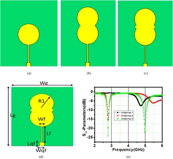
The proposed single-element antenna is constructed with low-cost FR4 substrate material with a thickness of 1.6 mm, a loss tangent value of 0.02, and a relative permittivity of 4.3. The proposed work was initially designed for 4.8 GHz by using a conventional circular micro-strip patch antenna with a radius of 8 mm. Later, another circular shape was attached with a conventional antenna-like doublet shape, and finally a triangular shape was inserted in the middle of both edges to attain the dual-band resonant frequency of 2.7 and 4.9 GHz. Figures 1(a)–1(e) show the step-by-step design of the proposed antenna and S-parameter results. Figure 2(b) shows the VSWR result which satisfied the <2 (Table 1).
Proposed single-element antenna. (a) Antenna 1; (b) antenna 2; (c) antenna 3; (d) proposed antenna; (e) S-parameter result of all the antennas.

Proposed single-element (a) S 11 parameter result; (b) VSWR result.

Dimensions of the proposed single-element antenna

Design of 1 × 2 MIMO antenna 2
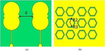
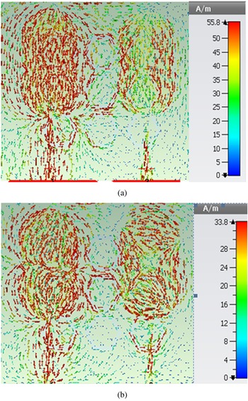
In this session, two similar antennas are used to design a 1 × 2 MIMO antenna. The antennas are separated by a 12 mm distance. The overall dimension of the desired MIMO antenna is 55 mm × 51 mm × 1.6 mm. The desired MIMO antenna is shown in Fig. 3(a). For better isolation, partial ground is introduced which shows the back view of Fig. 3(b). The dimensions of the inner and outer ring hexagonal circle are 5 and 4 mm, respectively; DGS low improvement of bandwidth is achieved and the transmission coefficients are also not <−20 dB. Figure 4 shows the simulated performance of the original MIMO antenna reflection coefficients (without metamaterial unit cell). Figure 5 shows the surface current distribution at 2.7 and 5.2 GHz. When one port is activated, the current density on the non-excited antenna element is extremely high, resulting in significant mutual coupling between the two radiating components.
(a) Front view configuration of the 1 × 2 MIMO antenna (b) back view.

Reflection coeffiecient result of the MIMO antenna.

Surface current distribution of the MIMO antenna. (a) 2.7 GHz; (b) 5.2 GHz.

Design of metamaterial MIMO antenna 3
In “Antenna design 1” section, the mutual coupling increases due to the low distance between the patch antennas but as the separation between the two elements is increased the mutual coupling can be reduced. But without increasing the distance, the MNG unit cell is placed in between the radiating elements; this leads to reduced mutual coupling. Due to the introduction of MNG, an 8.2 GHz frequency band was additionally obtained, which is used for ITU band applications. Figure 6(a) shows a metamaterial-based MIMO antenna, Fig. 6(b) shows the MNG unit-cell structure, and Table 2 shows the dimensions of the proposed metamaterial unit cell.
Proposed metamaterial-based MIMO antenna. (a) Front view; (b) unit cell.

Dimensions of the proposed metamaterial unit cell

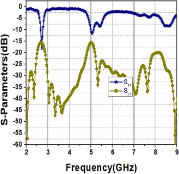
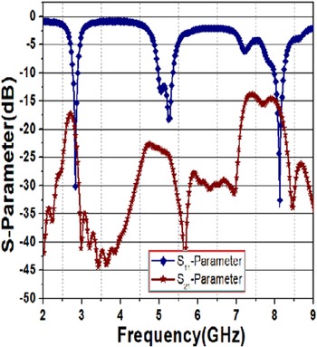
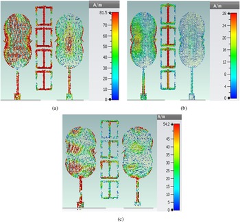
In this proposed design due to the unit-cell structure, the center frequency is shifted from 4.9 to 5.2 GHz, which is useful for WLAN applications. The unit cell is designed for a 2.7 GHz operating frequency. Figure 7 shows the S 11and S 21 results of the three bands metamaterial MIMO antenna. At 2.7 GHz, S 11 and S 21 are −30 and 18.35 dB, respectively; at middle frequency, S 11 is −18.99 dB and S 21 is −23.32 dB; and at 8.2 GHz, S 11 is −34.43 dB and S 21 is −17.75 dB. By the observation, the center frequency band achieved good isolation other than two band frequencies. Figures 8(a)–8(c) show the surface current distribution at 2.7, 5.2, and 8.2 GHz. At 2.7 GHz, we observe that majority of the current flow in the metamaterial unit cell in comparison to second radiating element as a result of minimal mutual coupling is obtained. At 5.2 GHz, maximum current flow in the metamaterial unit cell and no current flow in the second radiating element result in extremely low mutual coupling. At 8.2 GHz, the majority of the current flows in the metamaterial unit cell compared to the second radiating element result in low mutual coupling.
S 11 and S 21 metamaterial-based MIMO antenna.

Surface current distribution at (a) 2.7 GHz; (b) 5.2 GHz; and (c) 8.2 GHz.

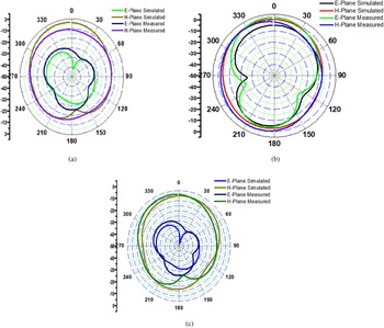
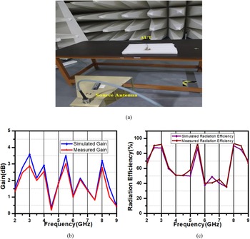
Other important antenna parameters such as antenna radiation pattern, gain, and antenna efficiency are determined for appropriate application. In this way, the proposed antenna analysis with the help of the anechoic chamber measured and simulated the results of E and H plane radiation pattern, gain, and efficiency, which is shown in Figs 9 and 10, and Table 3 reported the comparison of simulated and measured values. By observing this radiation pattern, the results are nearly omnidirectional pattern which means they are uniform in all the plane directions. This kind of pattern is recommended for Wi-MAX/WLAN/ITU bands.
Radiation pattern at (a) 2.7 GHz; (b) 5.2 GHz; and (c) 8.2 GHz.

The photographs of antenna under measurement for (a) radiation pattern; (b) gain; (c) radiation efficiency.

Proposed antenna simulated and measured results

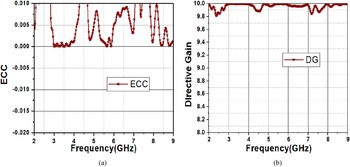
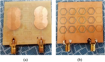
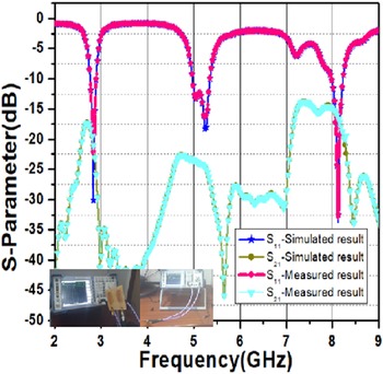
The measured and simulated 3D radiation patterns at frequencies of 2.7, 5.2, and 8.2 GHz of the designed MIMO antenna are shown in Fig. 9. The measurement is carried out by using a Schwarz ZVL vector network analyzer and a double ridge guide horn antenna setup inside the anechoic chamber. The anechoic chamber is used to get perfect measurement data, which significantly reduces the external effect of soundings. Figure 10 shows the photograph of the antenna under test for obtaining the radiation pattern, gain, and radiation efficiency. According to the findings, the measured and simulated results are in excellent agreement with the proposed MIMO antenna at 2.7 and 8.2 GHz which produce a quasi-omnidirectional radiation pattern, and 5.2 GHz produces an omnidirectional pattern. The simulated and measured antenna radiation efficiency average value is 85% in the operational frequency bands. At the desired frequency bands, the gain of the simulated and measured antenna is nearly identical. Figure 11 shows the performance analysis parameters of the enveloped correlation coefficient (ECC) and directive gain (DG). At the operational frequencies, the proposed MIMO antenna has a simulated ECC of <0.01, whereas the DG is 9.998 magnitude. Figure 12 shows the front view and back view of the prototype antenna, and Fig. 13 shows the simulated and measured results of the proposed antenna. Table 4 shows a comparison table for various MIMO antennas with existing work.
MIMO characteristics plot (a) ECC; (b) DG.

Prototype antenna (a) front view and (b) back view.

Proposed antenna measured and simulated results.

Comparison table for various MIMO antennas with existing work

MIMO antenna characteristics
The efficiency of MIMO antennas in terms of diversity must be measured. The ECC is a measurement of the correlation between radiation elements. The ECC's low value provides high isolation between antennas. Radiation variations or scattering parameters may be used to quantify the factor. The enveloped correlation, which is simply the square of the correlation coefficient, can be determined easily and rapidly from S-parameters for a basic two-port network in a standardized multipath environment. ECC can be calculated using equation (1).

Directive gain
DG measures the transmission power loss for the MIMO systems. The DG could be measured using equation (2).

Metamaterial unit-cell configuration to minimize mutual coupling
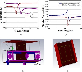
The desired metamaterial structure exhibits the property of negative permeability. The antenna is printed on FR4 substrate material with a thickness of 1.6 mm, a dielectric constant value of 4.3, and 0.02 loss tangent tan (δ). The characteristics of the metamaterial unit cell are analyzed with the help of S 11 and S 21 which is reported in Fig. 14(a). It shows that the phase difference is 180 degrees and proves that it satisfies the basic characteristics. The effective real and imaginary part of metamaterial unit cell is in Fig. 14(b). It proves the negative permeability characteristics of the metamaterial unit cell. Figures 14(c) and 14(d) show the simulation set up with boundary conditions and a two-port representation of the unit cell.
Unit-cell characteristics plot: (a) S-parameters; (b) effective permeability; (c) simulation set up of the unit cell; (d) two-port representation of unit cell.

Parametric study of metamaterial unit cell
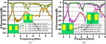
In this section, the parametric analysis was carried out in order to evaluate the performance of MIMO system and response of one unit-cell and two unit-cell S-parameter is shown in Fig. 15(a). The single unit cell is introduced between radiating elements. Later, two unit cells are placed. By observing the return loss value of both one and two unit cells, which is similar, an additional frequency of 8.2 GHz was also obtained because of indirect coupling of the metamaterial unit cells. However, the return loss value is not an acceptable value for frequencies of 2.7 and 5.2 GHz. In order to make further improvements, three and four unit cells are arranged and analyzed. The return loss results of the three and four unit cells are shown in Fig. 15(b) and it has shown extremely good impedance matching.
S-parameter result: (a) one and two unit cells; (b) three and four unit cells.

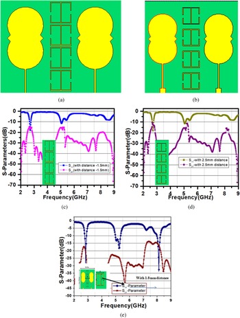
The distance between each unit cell is taken at 1.8 mm to obtain good isolation and lower return loss values. The analysis is carried out at a distance of 2.5, 1.5, and 1.8 mm. The return loss results are shown in Fig. 16. It observed that the distances of 2.5 and 1.5 mm unit cells exhibited low return loss and low isolation values when compared to the proposed antenna with a distance of 1.8 mm.
Distance between metamaterial unit cells: (a) 1.5 mm; (b) 2.5 mm; (c) S-parameter of the 1.5 mm; (d) S-parameter of the 2.5 mm; (e) S-parameter of the 1.8 mm.

Conclusion
The present study proposes a 1 × 2 MIMO MNG for reducing the mutual coupling of tightly packed radiating elements. In comparison to previous studies, the suggested technique provides superior isolation between antennas. At 2.7, 5.2, and 8.2 GHz, the isolation values are 17.85, 24.35, and 15.45 dB, respectively. In summary, the antenna may be recommended for use in WIMAX, WLAN, and ITU operational frequency bands.
Acknowledgement
This work is supported by DST science and engineering research board (SERB) with file no: EEQ/2016/000391.
 Pasumarthi Suneetha is working as an Assistant Professor in Vignan's Institute of Information Technology(A), Visakhapatnam, India. She received her B.Tech. degree in 2008 from JNTU Kakinada, the M.Tech. degree in 2013 from JNTU Kakinada. She is pursuing the Ph.D. degree from VFSTR University, Guntur, AP, India. Her areas of interest are MIMO antennas and wireless communications. She published 10 publications in reputed international journals and conferences.
 K. Srinivasa Naik has received his Bachelor of Engineering in Electronics and Communication Engineering, Master of Engineering, and Ph.D. degrees from Andhra University. At present, he is working as an Associate Professor in the Department of Electronics and Communication Engineering, Vignan's Institute of Information Technology (A), Duvvada, Visakhapatnam. He has presented more than 40 technical papers in reputed journals. He completed One DST project worth 50 lakhs. He is a life member of SEMCE (I). His research interests include array antennas, EMI/EMC, communications, field theory, and instrumentation.
 Pachiyannan Muthusamy received the Ph.D. degree in Information and Communication Engineering in the area of UWB antenna at Anna University, Chennai, India. He is currentlyworking toward the DGS structure-based UWB antenna for WBAN applications and object detection. He has 12 years of both academic and industrial experience and has published several international journal and conference papers. He is currently working as an Associate Professor in the ECE department at Vignan's Foundation for Science, Technology & Research. He is working on antenna compactness using DRA and meta materials. His research area includes UWB antennas, coplanar waveguides, meta materials, DRA, and RF circuits.