Introduction
The future mobile access technology needs high spectral efficiency and wide channel capacity [Reference Chin, Fan and Haines1–Reference Shafi, Molisch, Smith, Haustein, Zhu, Silva, Tufvesson, Benjebbour and Wunder3], which can be fulfilled by incorporating wide bandwidth and MIMO technology in 5 G mobile terminals. Therefore, an ultra-wideband (UWB) multiple input multiple output (MIMO) antenna is designed for mobile devices. In MIMO antennas, pattern diversity is utilized to exploit multipath fading. Pattern diversity comprises at least two neighboring antennas with various radiation patterns. This diversity utilizes directional antennas, which are generally physically isolated by a short gap [4]. Antennas with various radiation patterns are utilized in the pattern diversity strategy. These two distinct kinds of antennas will encounter uncorrelated fading and henceforth this diversity idea is taken advantage of to recuperate the communicated data at receiving end. To accomplish great performance under this plan, antennas should be set nearer. For instance, cell phones have double antennas such as microstrip and dipole antennas [5]. Pattern diversity further develops the unwavering quality of a message signal by utilizing at least two communication channels with various attributes. The pattern diversity likewise assumes an indispensable part in removing fading, co-channel interference, and keeping away from error bursts [Reference Choudhary, Jha and Sharma6].
In the last few years, the MIMO antenna is designed with different AE arrangements such as orthogonal, parallel, 180° rotation, etc. to enhance isolation. To further increase the isolation, in each arrangement, different types of decoupling techniques (DT) are used as shown in Table 1 such as parasitic element, orthogonal position, 180° rotation, decoupling structure (DS), defected ground structure (DGS), metamaterial, neutralization line (NL) and carbon black film, etc. The description, limitation, and highest isolation of each DT are also mentioned in Table 1. Based on Table 1, it is clear that each DT has its limitation/s and the highest isolation provided by these DTs is 25 dB. However, for applications such as mobile terminals and future wireless communications, there is a need for isolation of more than 25 dB.
Different types of decoupling techniques

As of late, the new concept of utilizing the CM for exciting distinct modes has been proposed to achieve distinct radiation patterns and high isolation in MIMO antenna with no extra DS [Reference Li, Lau, Ying and He22–Reference Bouezzeddine and Schroeder24]. This new strategy can be stretched out to construct a UWB MIMO antenna. It has been suggested that the same CM is not shared by the two AEs at two edges of the ground surface [Reference Li, Lau, Ying and He22]. Because the two AEs do not share the same CM on the ground surface, they are isolated easily with distinct patterns and low mutual coupling. But, a mobile antenna requires excitation of the ground surface successfully for optimizing the performance of the antenna. The above-mentioned design concept for the MIMO antenna can be improved by designing the two AEs for stimulating distinct CM on the ground surface. Furthermore, in place of half-loop AE, antipodal Vivaldi AE (AE1) is used. Additionally, circular monopole AE is also utilized (AE2). Both AEs are wideband antennas and useful for obtaining the UWB frequency range.
This research paper presented a printed UWB MIMO mobile antenna explained with the help of CM. The dual distinct AEs are kept on the opposite edges of the antenna's rectangular-shaped ground surface. The two AEs have dissimilar current distributions, which results in the excitation of dissimilar CM. The two AEs refer to as magnetic and electric sources. Thus exciting two orthogonal CM. The distinct CM can produce the required isolation and distinct radiation patterns. Like this, the same concept of CM has been used in the presented UWB MIMO antenna. The tested results verify that the presented technique operates well for the UWB MIMO mobile antenna.
Construction of presented antenna
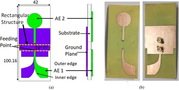
The MIMO antenna is designed by placing the ground surfaces of two AEs (AE 1 and AE 2) at the opposite edges of the rectangular structure of size 10 × 42 mm2 [Reference Zhao, Yeo and Ong25]. The AE1 is the antipodal Vivaldi antenna and AE 2 is the circular monopole antenna. The complete simulated and fabricated structures of the designed antenna are displayed in Figs 1(a) and 1(b), respectively. The MIMO antenna is designed on an FR4 dielectric substrate with a dielectric constant of 4.4, the height of substrate of 1.4 mm, and a loss tangent of 0.02. The complete chip size of the presented MIMO antenna is 100.16 × 42 mm2.
(a) Structure and dimensions (in mm) of the presented antenna and (b) fabricated antenna with front and back view.

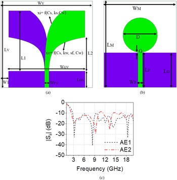
The individual design of AEs are displayed in Figs 2(a) and 2(b), respectively with the S ii plot in Fig. 2(c). Additionally, the dimensions of all the variables of both AEs are shown in Table 2. In the AE1, dual exponentially tapered symmetric patches are designed on the back and front sides of the substrate with microstrip transmission line feeding. The inner and outer edge tapers of the AE1 are referred as


where x o and x i represent the gaps from the slot centerline to the outer and inner edges, respectively [Reference Hood, Karacolak and Topsakal26]. The C s determine slot width at the feeding interface and k s determine the rate by which the slot opens. The x o is the function of coefficients of outer edge taper such as C w, k w, and sf. The design equation of AE1 is shown below equation (3):

here, frL is a lower resonance frequency in (GHz). When the value of L1 in mm and ɛr are put in equation (3), f rL = 3.26 GHz (calculated), which is almost matched with the simulated value (3.2 GHz).
Structure of (a) Antipodal Vivaldi antenna (AE1), (b) Circular monopole antenna (AE2), and (c) S 11 of AE1 and AE2.

Values of the various parameters of AE1 and AE2

In AE2, a circular monopole antenna with microstrip line feeding is designed on the front side of the substrate. The design equation of AE2 is given by the following equation [Reference Thomas and Sreenivasan27]:

where, L G = Length of the ground surface, D = Diameter of the circle, G = Distance between patch and ground surface, A G = Area of the ground plane, A P = Area of the circular patch, and ɛr = Dielectric constant of the substrate. Note that all dimensions of AE2 are in cm for calculating f rL in (GHz). By putting the values of the variable in the formula (4), f rL = 3.212 GHz (calculated), which is almost equal to the simulated value of 3.2 GHz.
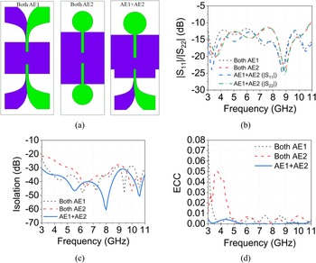
As presented in Fig. 3, three cases of the presented antenna are compared. In the first case, both antenna elements are antipodal Vivaldi antennas and in the second case, both antenna elements are circular monopole antennas, and the third case is proposed MIMO antenna with AE1 and AE2, which are oriented in 180° direction with a spacing of 10 mm. It is concluded that in all cases UWB bandwidth is achieved with better impedance matching and isolation of the proposed MIMO antenna higher than in the other two cases as presented in Table 3. Also, the peak value of ECC is the lowest in the proposed MIMO antenna case (Table 3).
(a) Structure of three cases of MIMO antenna, (b) Sii, (c) Isolation, and (d) ECC.

Comparison between three cases of MIMO antenna

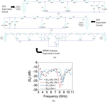
Figure 4(a) displays the equivalent circuit model of the presented AEs and MIMO antenna. This circuit is designed by examining the s-parameter Sii of the antenna using the circuit simulator of HFSS. By attaining the s-parameter, the overall circuit has been changed to indicate the properties of the antenna. The patch is represented by a parallel RLC circuit and the probe inductance is represented by a series inductor. The presented antenna is lossy because of the use of resistors in an equivalent circuit and also both ports are fed with a lossy transmission line, which is implemented with a resistively loaded microstrip line [Reference Pfeiffer, Steffen and Kakas28]. As shown in Fig. 4(a) all microwave ports are terminated with a 50 Ω load impedance and all other resistors are equal to 50 Ω. The structure of step discontinuity is modeled as a T-structure containing two inductors and a capacitor. The 10 mm gap can be modeled as a group of R-L-C, which is placed in the middle of AE circuits. The starting values of the resistors, capacitors, and inductors are obtained from the references [Reference Kasi, Jalil and Chakrabarty29, Reference Jangid and Kumar30] and to obtain the desired bandwidth, these values are optimized. The equivalent circuit reflection coefficients are almost identical to simulated reflection coefficients as shown in Fig. 4(b).
(a) Equivalent circuit diagram of AEs and MIMO antenna and (b) Sii of equivalent circuit and simulated MIMO antenna.

Characteristic modes (CM) analysis
The CM analysis is carried out using an integral equation solver of CST Studio Suite. The antenna structure should be a perfect electric conductor (PEC) with 0 mm height on account of the impediments of the integral equation solver and the layer of the substrate should be eliminated for the benefit of MoM computing. The characteristic angle (CA) is used to check whether the PEC structure radiates efficiently or not and modal significance (MS) is used to evaluate the contribution of each mode in the total electromagnetic. Both can be measured using the following expressions [Reference Liu, Tang, Wang, Zhang, Ma, Fu and Cui31]


where λ n is the Eigen values, and n is the order index of each mode.
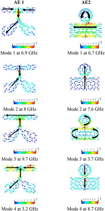
The predicted CAs of the presented AE 1 and AE 2 are presented in Figs 5(a) and 5(b), respectively. The four CM of the AE1 resonates at 6.7, 7.6, 3.7 and 8.7 GHz, while the four CM of the AE2 resonate at 6.9, 8, 9.7 and 3.2 GHz. The equivalent modal significances (MSs) of the four CM of the AE 1 and AE 2 are displayed in Figs 5(c) and 5(d), which shows that the MSs curves of AE 1 are sharper than AE 2, therefore, the four CM of AE 1 have narrower bandwidth than AE 2. This fact can be clarified by seeing their quality (Q) factors. AE 1 has high Q-factors than AE 2 resulting in narrower bandwidth [Reference Hansen and Collin32]. The bandwidth of AE 2 (3 to 10.3 GHz) is larger than AE 1 (3 to 9.5 GHz) when simulated separately (Fig. 2(c)). With a high Q-factor, impedance matching of a small electrical size antenna gets deteriorated, when its impedance bandwidth, resonance frequency, and radiation efficiency are constant [Reference Hansen and Collin32]. The current distribution of all modes of the AE 1 and AE 2 is shown in Fig. 6. In AE1, the main current of Mode 1 has the same orientation in the feeding line and tapered patch. In Mode 2, the main current inverts its orientation at the ground taper. The main current of Mode 3 has the same orientation in the ground taper, and the current flows from right to left in the rectangular ground (connected to the taper). In Mode 4, the main current reverses its direction at the feeding point and after starting the taper. In AE2, the main current of Mode 1 flows in the loop (anti-clockwise) in the circular monopole patch, and single direction on the ground from right to left. The main currents of Mode 2 have an upward direction and the main direction of Mode 4 has a downward direction. In Mode 3, the main current flows in an anti-clockwise direction in the ground surface and circular monopole.
(a) Characteristic angles of AE 1, (b) Characteristic angles of AE 2, (c) Modal significances of AE 1 (d) Modal significance of AE 2, and (e) Modal significance of MIMO antenna.

The current distribution of all modes of AE 1 and AE 2.

CM analysis of presented antenna
To disclose the process of obtaining the distinctive radiation patterns in the designed antenna, the connection between the AEs and the ground plane is investigated. For instance, the most significant CMs of both AE1 and AE2 are chosen, which are excited around 6.8 GHz as presented in Figs 5(a) and 5(b). Thus, CM analysis emphasizes 6.8 GHz. The MSs of the antenna's ground surface of the MIMO antenna are portrayed in Fig. 5(e), which indicates that Mode 1 and Mode 3 of the ground surface are excited around 6.8 GHz.
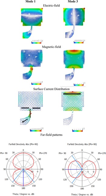
Figure 7 shows the electric fields, magnetic fields, surface current distributions, and far-field patterns of the antenna's ground surface at 6.8 GHz. Mode 1 has strong electric fields and nulls of magnetic fields and Mode 3 has nulls of electric fields and strong magnetic-field around the place of AEs (Fig. 7). As displayed in surface current distribution, there is strong current distribution around AE1 in Mode 1 and AE2 in Mode 3. Consequently, AE1 excites Mode1 and AE2 excites the Mode3 of the ground surface. Furthermore as displayed in Fig. 5, the radial current exuding from AE1 at 6.9 GHz infers that AE1 acts as an electric source, which implies that the AE mainly stores electric energy. When an electric source is appropriately located at the strong electric-field location of a CM, it excites the CM successfully [Reference Li, Lau, Ying and He22]. Thus, AE1 can excite Mode1 of the ground surface successfully. Interestingly, the current of AE2 structures a loop at 6.7 GHz. On such an occasion, AE2 refer to as a magnetic source, which implies that the AE mainly stores magnetic energy. When a magnetic source is appropriately located at the strong magnetic-field location of a CM, it can energize the CM efficiently [Reference Li, Lau, Ying and He22]. In like manner, AE2 excites Mode 3 of the ground surface successfully. The far-field radiation patterns of Mode 1 and Mode 3 of the ground surface are introduced in Fig. 7. The bidirectional pattern of Mode 1 has its greatest radiation along the 180° direction, while the bidirectional pattern of Mode 3 has its most extreme radiation along the 90° direction. The two radiation patterns have practically a similar shape with orthogonal direction. It is derived from this that the two patterns are orthogonal to one another.
Predicted electric fields, magnetic fields, surface current distribution, and far-field patterns of the antenna's ground surface at 6.8 GHz of Mode 1 and Mode 3.

Results and discussion
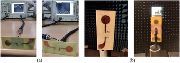
The measurement of s-parameters of the presented antenna is tested using Vector Network Analyser and the measurement of far-field patterns is done in an anechoic chamber as displayed in Fig. 8.
Measurement setup (a) VNA setup for S 11 and S 21 measurement, (b) Anechoic chamber setup for radiation pattern measurement.

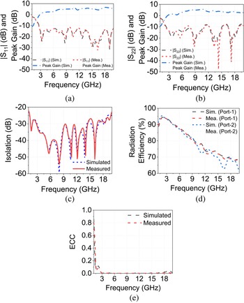
Both simulated and measured results are almost identical. The measured operating bandwidth of AE1 is from 2.57 GHz to >20 GHz as illustrated in Fig. 9(a) with measured peak gain from 0.83 to 6.4 dB within the bandwidth of 3 to 20 GHz. The experimental operating bandwidth of AE2 is from 2.23 GHz to 11.09 GHz with a slight mismatch around 7.5 GHz and the measured peak gain of AE2 is from 0.86 dB to 6 dB within the bandwidth 3 to 20 GHz as presented in Fig. 9(b). The reasons for the slight variations in simulated and experimental s-parameters and gain are fabrication tolerance, material loss, and connector loss. The presented MIMO antenna has isolation>30.1 dB with a bandwidth from 2.82 GHz to 14.5 GHz, as presented in Fig. 9(c). The presented antenna shows radiation efficiency of over 75% in the UWB range, as demonstrated in Fig. 9(d). The envelope correlation coefficient (ECC) is the essential factor to predict the MIMO/diversity performance. It determines how much the radiation patterns of AEs are differing. The ECC is <0.08 from 1.54 GHz to >20 GHz as presented in Fig. 9(e), which is calculated using S-parameters [Reference Addepalli and Anitha7].

where $\overrightarrow {F_i}$ and $\overrightarrow {F_j}$
 are the ith and jth antenna radiated fields.
MIMO Antenna results: (a) S-parameters and peak gain of AE1, (b) S-parameters and peak gain of AE2, (c) Isolation between AE1 and AE2, (d) Radiation efficiency, and (e) ECC.

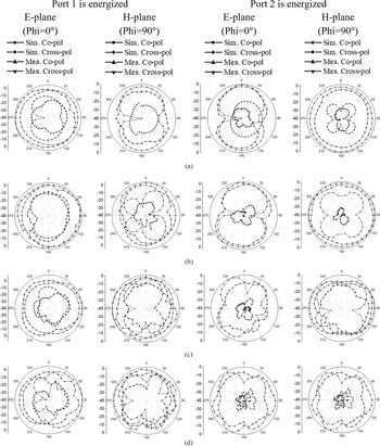
As shown in Fig. 10, when port 1 is energized, an almost omnidirectional shape radiation pattern is attained in E-plane, and a bidirectional shape radiation pattern is achieved in H-plane. However, when port 2 is excited, a bidirectional shape radiation pattern is obtained in E-plane and an almost omnidirectional shape radiation pattern in H-plane. Because of this swapping of the shape of the radiation patterns, high isolation is obtained and very low ECC is achieved. As shown in Fig. 11, 7 GHz indicates approximately a second-order harmonic, and a more complex current pattern is generated at 9 GHz, as compared to the third-order harmonic. Therefore, because of the generation of higher-order modes at higher frequencies, cross-polarization increases. The maximum acceptable limit of cross-polarization is −15 dB for practical purposes. The cross-polarized patterns in H-plane are almost comparable to the acceptable limits.
Radiation patterns when Port1 and Port 2 are energized at (a) 3 GHz,(b) 5 GHz,(c) 7 GHz, and (d) 9 GHz.

Surface current distribution at (a) 7 GHz and (b) 9 GHz.

In Table 4, the performance of the proposed antenna is compared with recently reported UWB MIMO antennas with two AEs. The highest isolation is obtained by the proposed antenna using excitation of different modes in the ground surface shared by antipodal Vivaldi and circular monopole AEs as compared to other recently reported antennas. In reference [Reference Jangid and Kumar30], the same concept of exciting different CM in the ground surface is used for pattern diversity and isolation increment. However, this antenna is not applicable for UWB applications because complete UWB bandwidth is not achieved by both AEs. Also, the isolation of this antenna is lower than the presented antenna.
Comparison between the presented antenna and other two-port UWB MIMO antennas.

Conclusion
A printed UWB MIMO antenna with improved isolation and distinct (far-field) patterns is designed, which is explained using CM. The designed dual AEs stimulate different CM over the working frequency band, therefore obtaining high isolation without DS requirement and distinct far-field radiation patterns. The measured results verify that both AEs work from 2.6 GHz to 11 GHz. The isolation is >30.1 dB in UWB. The peak realized gain is more than 0.83 dBi. The radiation efficiency is above 75%. The ECC is below 0.08. The presented antenna has an appropriate design for emerging mobile terminals.
 Shailesh Jayant received the B.Tech. degree in electronics and communication engineering from Bhagwan Parshuram Institute of Technology, which is affiliated with Guru Gobind Singh Indraprastha University (GGSIPU), Delhi-110089, India in 2014, and an M.Tech, degree in microwave electronics from the Department of Electronic Science, University of Delhi, South Campus, New Delhi- 110021, India, in 2017. She is currently pursuing a Ph.D. degree in electronics and communication engineering from Ambedkar Institute of Advanced Communication Technologies and Research, Delhi–110031, India (also affiliated to GGSIPU), Delhi- 110078, India). She has published six journal papers and three IEEE conference papers. Her current research interests include the design of UWB MIMO antenna, microwave filters, and broadband power amplifiers.
 Garima Srivastava is presently working as an assistant professor in the Department of Electronics & Communication Engineering at Netaji Subhas University of Technology (Formerly Ambedkar Institute of Advanced Communication Technologies & Research), Geeta Colony, Delhi. She had joined this institute in 2011, through selection by Union Public Service Commission. She holds her Ph.D. in electronics and communication engineering in the area of RF and microwave and she received her master's degree in electronics from Allahabad University, India. She has a keen interest in the microstrip antenna, UWB antenna, reconfigurable, and circularly polarized antenna, wireless communication, and MIMO technologies. She has more than 35 published papers in refereed National/International Journals & Conferences.
 Sachin Kumar received the B.Tech. degree from Uttar Pradesh Technical University, Lucknow, India, in 2009, and the M.Tech. and Ph.D. degrees from Guru Gobind Singh Indraprastha University, Delhi, India, in 2011 and 2016, respectively. He was a post-doctoral research fellow at the College of IT Engineering, Kyungpook National University, South Korea, from 2018 to 2021. He is currently working as a research assistant professor with the Department of Electronics and Communication Engineering, SRM Institute of Science and Technology, Chennai, India. Dr. Kumar has published 04 patents, 02 books, and more than 120 research articles in several peer-reviewed international journals and conferences. He serves as an Advisory Board Member for the Journal Measurement, Editorial Board Member for the Journal Current Chinese Science, and Guest Editor for the International Journal of Antennas and Propagation. He is also a frequent reviewer for more than 60 scientific journals and book publishers. He serves as the session chair, organizer, and member of the technical program committee for various international conferences, summits, and workshops. He was a recipient of the Teaching-cum-Research Fellowship from the Government of NCT of Delhi, India, and the Brain Korea 21 Plus Research Fellowship from the National Research Foundation of South Korea. He is a Life Member of the Indian Society for Technical Education and the Korean Institute of Electromagnetic Engineering and Science.