1. Introduction
In inertial confinement fusion (ICF) (Lindl Reference Lindl1998; Atzeni & Meyer-ter-Vehn Reference Atzeni and Meyer-ter-Vehn2004) a spherical capsule, containing deuterium–tritium (DT) thermonuclear fuel, is heated and compressed using laser beams. Under specific conditions the implosion of the capsule can result in the confinement of a small mass of fuel at the ignition conditions for DT fusion reactions (
 $T\approx 10~\text{keV}$
and
 ${\it\rho}R\approx 0.3~\text{g}~\text{cm}^{-2}$
). Successful ignition is followed by the propagation of a thermonuclear burn wave through the surrounding fuel, ultimately achieving the final goal of a net energy gain
 $G$
. Multiple powerful laser beams are used to provide the relatively large energy required –
 ${\approx}\text{MJ}$
in a few ns – for the implosion of the capsule. Large laser facilities such as the National Ignition Facility (NIF) in the USA (Miller, Moses & Wuest Reference Miller, Moses and Wuest2004; Moses et al.
Reference Moses, Boyd, Remington, Keane and Al-Ayat2009; Lindl et al.
Reference Lindl, Landen, Edwards and Moses2014) and the Laser Mégajoule (LMJ) in France (Lion Reference Lion2010) are configured to test the indirect drive (ID) scheme (Lindl Reference Lindl1995), where a fraction of the laser beam energy is first converted into an X-ray field which drives the capsule implosion. These facilities have been designed to generate
 ${\approx}20~\text{ns}$
laser pulses delivering a total energy of almost 2 MJ. The Omega laser facility in the USA (Boehly et al.
Reference Boehly, Brown, Craxton, Keck, Knauer, Kelly, Kessler, Kumpan, Loucks, Letzring, Marshall, McCrory, Morse, Seka, Soures and Verdon1997) is configured to test aspects inherent to the alternative direct drive scheme (Nuckolls et al.
Reference Nuckolls, Wood, Thiessen and Zimmermann1972; Bodner et al.
Reference Bodner, Colombant, Gardner, Lehmberg, Obenschain, Phillips, Schmitt, Sethian, McCrory, Seka, Verdon, Knauer, Afeyan and Powell1998), in which the laser beams directly irradiate the capsule, whilst other facilities such as Orion in the UK (Hopps et al.
Reference Hopps, Danson, Duffield, Egan, Elsmere, Girling, Harvey, Hillier, Norman, Parker, Treadwell, Winter and Bett2013), GEKKO XII in Japan (Mima et al.
Reference Mima, Tanaka, Kodama, Johzaki, Nagatomo, Shiraga, Miyanaga, Murakami, Azechi, Nakai, Norimatu, Nagai, Taguchi and Sakagami2007) and the Shenguang series in China (He & Zhang Reference He and Zhang2007) are devoted to the study of different aspects of the underlying physics.
Achieving ignition conditions is a significant challenge. In addition to the conventional central ignition approach, several alternative approaches are also the subject of study, including fast ignition (FI) (Tabak et al.
Reference Tabak, Hammer, Glinsky, Kruer, Wilks, Woodworth, Campbell, Perry and Mason1994) and shock ignition (SI) (Betti et al.
Reference Betti, Zhou, Anderson, Perkins, Theobald and Solodov2007). In the FI scheme, a secondary laser-accelerated particle beam is utilized to heat a small volume of a pre-compressed DT fuel to the ignition temperature. The FI scheme was originally conceived to use relativistic electron beams (Azechi et al.
Reference Azechi, Mima, Shiraga, Fujioka, Nagatomo, Johzaki, Jitsuno, Key, Kodama, Koga, Kondo, Kawanaka, Miyanaga, Murakami, Nagai, Nakai, Nakamura, Nakamura, Nakazato, Nakao, Nishihara, Nishimura, Norimatsu, Norreys, Ozaki, Pasley, Sakagami, Sakawa, Sarukura, Shigemori, Shimizu, Sunahara, Taguchi, Tanaka, Tsubakimoto, Fujimoto, Homma and Iwamoto2013; Shiraga et al.
Reference Shiraga, Nagatomo, Theobald, Solodov and Tabak2014), whilst more recently the use of laser-accelerated protons (Gus’kov Reference Gus’kov2001; Roth et al.
Reference Roth, Cowan, Key, Hatchett, Brown, Fountain, Johnson, Pennington, Snavely, Wilks, Yasuike, Ruhl, Pegoraro, Bulanov, Campbell, Perry and Powell2001; Temporal, Honrubia & Atzeni Reference Temporal, Honrubia and Atzeni2002) or even ion beams (Hegelich et al.
Reference Hegelich, Albright, Cobble, Flippo, Letzring, Paffett, Ruhl, Schreiber, Schulze and Fernandez2006; Fernandez et al.
Reference Fernandez, Honrubia, Albright, Flippo, Gautier, Hegelich, Schmitt, Temporal and Yin2009; Tikhonchuk et al.
Reference Tikhonchuk, Schlegel, Regan, Temporal, Feugeas, Nicolai and Ribeyre2010; Honrubia et al.
Reference Honrubia, Fernández, Hegelich, Murakami and Enriquez2014) has been explored. In the case of the SI concept, in contrast, a second high-intensity (
 ${\approx}10^{15}~\text{W}~\text{cm}^{-2}$
), relatively short (
 ${\approx}\text{hundreds of ps}$
), laser pulse is used to generate a strong shock wave (hundreds of Mbar) that induces DT ignition in the pre-compressed fuel.
In the SI scheme, as in some versions of FI, it is assumed that the fuel will first be compressed using direct drive (Canaud et al. Reference Canaud, Garaude, Ballereau, Bourgade, Clique, Dureau, Houry, Jaouen, Jourdren, Lecler, Masse, Masson, Quach, Piron, Riz, Van der Vliet, Temporal, Delettrez and McKenty2007), where several laser beams irradiate a spherical capsule. For current ignition scale facilities an ID configuration allows for a more uniform capsule irradiation and consequently a much more robust capsule compression, but is not likely to be favourable for SI due to the difficulties of coupling the shock at later times through the hohlraum plasma. In addition, the DD scheme is more efficient and takes advantage of higher laser–capsule coupling that could be even further improved by applying zooming techniques (Lehmberg & Goldhar Reference Lehmberg and Goldhar1987; Canaud & Garaude Reference Canaud and Garaude2005; Temporal, Canaud & Le Garrec Reference Temporal, Canaud and Le Garrec2010), where the laser focal spot is dynamically adapted to the dimension of the contracting critical surface. The SI scheme promises to tolerate larger fuel non-uniformity in comparison with classical central ignition. However, careful control of the uniformity of the fuel during the compression is still a necessary condition to achieve the desired high SI-thermonuclear output (Canaud & Temporal Reference Canaud and Temporal2010). For SI in the context of the LMJ, compression will be driven by 80 laser beams arranged in 20 quads located in two cones. One way to improve the limited symmetry provided by this configuration is to tailor the laser spot intensity profile to achieve irradiance as uniformly as possible.
An initial simple method able to generate an optimal laser intensity profile is based on the illumination model (Skupsky & Lee Reference Skupsky and Lee1983). In this model the expansion of the plasma corona is neglected and the illumination of the capsule surface is approximated to the laser energy absorption. The method has the advantage of being very simple and has been used in a variety of studies (Murakami, Nishihara & Azechi Reference Murakami, Nishihara and Azechi1993; Murakami Reference Murakami1995; Canaud et al. Reference Canaud, Fortin, Dague and Bocher2002; Temporal et al. Reference Temporal, Ramis, Canaud, Brandon, Laffite and Le Garrec2011a , Reference Temporal, Canaud, Garbett, Philippe and Ramis2013, Reference Temporal, Canaud, Garbett and Ramis2014a ; Temporal & Canaud Reference Temporal and Canaud2011b ; Tian et al. Reference Tian, Shan, Zhang, Zhou, Liu, Bi, Zhang, Wang, Zhang and Gu2015), but the validity of its solutions has only been partially tested in two-dimensional (Temporal et al. Reference Temporal, Canaud, Garbett and Ramis2014b ) and three-dimensional hydrodynamics calculations (Ramis et al. Reference Ramis, Temporal, Canaud and Brandon2014).
It is generally accepted that the solutions of the illumination model are exact at time
 $t=0$
and could be sufficiently accurate only during a small time interval before the expanding plasma generates a large gradient length. Nevertheless, a comparative study of the non-uniformity of the shock wave produced by different solutions has not yet been performed. This is the goal of this paper: for a given LMJ configuration the optimal laser intensity profiles are first found by using the illumination model; then, these solutions are used as inputs in two-dimensional hydrodynamic simulations. In general the laser irradiation of the capsule generates an inward-moving shock wave that is not perfectly spherical. The characteristic root-mean-square (r.m.s.) non-uniformity of the simulated shock-front surface is used as a metric to determine the best laser intensity profile.
2. Optimal laser intensity profiles
It has recently been shown that uniform solutions of the illumination model can be obtained for any general laser–capsule configuration (Temporal et al.
Reference Temporal, Canaud, Garbett and Ramis2014c
). Once the number
 $n$
of the laser beams and their spatial distributions are defined, the model is solved by an iterative procedure. The method requires that the laser intensities are first initialized with given trial functions
 $g_{n}(x,y)$
. Then the illumination of a spherical surface can be calculated by adding the contributions of all
 $n$
laser beams, providing
 $I^{\prime }({\it\theta},{\it\varphi})=\sum _{n}g_{n}(x,y)(\boldsymbol{r}\boldsymbol{\cdot }\boldsymbol{r}_{n})^{{\it\beta}}~H(\boldsymbol{r}\boldsymbol{\cdot }\boldsymbol{r}_{n})$
, where
 $\boldsymbol{r}$
is the vector position of the target surface element and
 $\boldsymbol{r}_{n}$
is the vector direction of the
 $n$
th laser beam. The Heaviside step function
 $H$
prevents the irradiation of the hidden areas (shadow effect), whilst the factor
 ${\it\beta}$
is set to 1 in the original illumination model. Higher
 ${\it\beta}$
values are possible; these will act to increase the weight of the photons more normally incident to the surface in detriment to those nearly tangential to the target surface and can be used to approximate the angular dependence of laser energy absorption. To this end, the factor
 ${\it\beta}$
is sometimes increased to 2, as was first proposed by Schmitt (Reference Schmitt1984). The model takes advantage of the fact that there is a one-to-one correspondence between a position on the sphere (
 ${\it\theta},{\it\varphi}$
) and a position in the laser focal plane
 $(x_{n},y_{n})$
; moreover, simple transformations connect these coordinates:
 $x_{n}=\boldsymbol{r}({\it\theta},{\it\varphi})\boldsymbol{\cdot }(\boldsymbol{r}_{n}\wedge \boldsymbol{z})/|\boldsymbol{r}_{n}\wedge \boldsymbol{z}|$
and
 $y_{n}=\boldsymbol{r}({\it\theta},{\it\varphi})\boldsymbol{\cdot }(\boldsymbol{x}_{n}\wedge \boldsymbol{r}_{n})/|\boldsymbol{x}_{n}\wedge \boldsymbol{r}_{n}|$
. Once the illumination intensity
 $I^{\prime }({\it\theta},{\it\varphi})$
of the target is calculated it is possible to normalize all the
 $N_{B}$
trial intensity functions
 $g_{n}$
by scaling with
 $I_{0}/I^{\prime }$
, where
 $I_{0}$
is the desired uniform intensity, providing the new laser intensity solutions:
 $f_{n}(x,y)=g_{n}(x,y)[I_{0}/I^{\prime }({\it\theta},{\it\varphi})]$
. Thus, these solutions
 $f_{n}(x,y)$
guarantee optimum illumination of the spherical surface for arbitrary beam polar angle distributions, provided certain basic limitations on the number and distribution of beams are met.
As an application of the previous approach, a set of laser profiles have been calculated solving the illumination model for a two-dimensional irradiation configuration characterized by two laser beams at the polar angles 49° and 131°. This configuration corresponds to the two-dimensional description of the LMJ configuration, and thus the three-dimensional feature inherent to the 80 laser beams (20 quads) arranged in the two rings has been neglected. This is consistent with recent three-dimensional hydrodynamic calculations indicating that the azimuthal component of the non-uniformity becomes negligible for a number of laser beams per ring larger than six (Ramis et al.
Reference Ramis, Temporal, Canaud and Brandon2014). The optimal laser intensity profiles have been calculated for the two parameters
 ${\it\beta}=1$
and
 ${\it\beta}=2$
and where the trial function has been set to the cosines of the angle between the beam direction and the surface vector position:
 $g_{n}(x,y)=(\boldsymbol{r}\boldsymbol{\cdot }\boldsymbol{r}_{n})$
. These solutions provide a zero r.m.s. illumination non-uniformity and are shown in figure 1(a) and figure 1(b), respectively. Here the laser intensities have been normalized to one. Due to the nature of the illumination model, the laser intensity profiles are limited to a circular surface of radius
 $r_{0}$
(target radius). It is apparent that the maximum intensity is located off-axis in the direction of the equatorial areas. This is due to the need to compensate the under-illumination of the equator area since the two beams at 49° and 131° tend to over-irradiate the two polar caps. Thus, in a natural way, the method provides the movement of the laser intensity profiles towards the equator, as required by the polar direct drive technique (Skupsky et al.
Reference Skupsky, Marozas, Craxton, Betti, Collins, Delettrez, Goncharov, McKenty, Radha, Knauer, Marshall, Harding, Kilkenny, Meyerhofer, Sangster and McCrory2004). The two solutions shown in figure 1(a,b) are quite similar; nevertheless, the case with
 ${\it\beta}=2$
results in a nearly ellipsoidal profile with an axis ratio of almost 1:2 and a minor axis parallel to a meridian. Incidentally, this focal spot has a similar shape to the one expected at the LMJ facility. Indeed, due to the needs of the ID scheme, the laser intensity profile will be elliptical and characterized by a super-Gaussian of order 4 with full-widths at
 $1/e$
of
 ${\it\Delta}_{a}=1280~{\rm\mu}\text{m}$
and
 ${\it\Delta}_{b}=640~{\rm\mu}\text{m}$
, thus
 ${\it\Delta}_{a}/{\it\Delta}_{b}=2$
.
Optimized laser intensity profiles for the laser beams at co-latitude 49° (the same profiles as at 131° but rotated by
 ${\rm\pi}$
). Laser intensities are normalized to one and the scale colour ranges from 0 to 1. Frames (a) and (b) correspond to the parameter
 ${\it\beta}=1$
and
 ${\it\beta}=2$
, while frames (c) and (d) assume in addition a background factor of 55 %.

In a real laser facility the beams are affected by unavoidable uncertainties that degrade the quality of the irradiation. The error in the positioning of the capsule (TP, target positioning) as well as the beam mispointing (PE, pointing error) affect the desired laser–capsule coupling. In the case of the LMJ facility these errors, evaluated as r.m.s. values, are
 ${\it\sigma}_{TP}=20~{\rm\mu}\text{m}$
and
 ${\it\sigma}_{PE}=50~{\rm\mu}\text{m}$
. A strategy to mitigate against the negative effect of these uncertainties by imposing an additional uniform background laser intensity over the entire spot was recently proposed (Temporal et al.
Reference Temporal, Canaud, Garbett, Philippe and Ramis2015). Thus, a laser shape with background larger than the capsule radius (
 $r_{0}$
) and characterized by a radius
 $r_{B}=r_{0}+2~\text{max}[{\it\sigma}_{TP},{\it\sigma}_{PE}]$
is guaranteed to be statistically effective in 95 % of the shots. In the case of our LMJ configuration a parametric study found that the optimal background value lies at 55 % of the maximum laser intensity (Temporal et al.
Reference Temporal, Canaud, Garbett, Philippe and Ramis2015). The illumination model has been used to generate the two optimal intensity profiles shown in figure 1(c) and figure 1(d), calculated with
 ${\it\beta}=1$
and
 ${\it\beta}=2$
in addition to a background of 55 %. In this case, due to the constraint set by the background, the minimum r.m.s. illumination non-uniformity could not be null but is evaluated as
 ${\it\sigma}_{0}=0.29\,\%~({\it\sigma}_{0}=0.38\,\%)$
for the case
 ${\it\beta}=1$
(
 ${\it\beta}=2$
). The mitigation provided by this background comes at the cost of increased total laser power, and for the laser shapes of figure 1(c,d) corresponds to a power increase of about 18 % (27 %) at a capsule of radius
 $r_{0}=1000~{\rm\mu}\text{m}~(r_{0}=500~{\rm\mu}\text{m})$
.
3. Two-dimensional hydro-simulation
The uniformity of the shock wavefront generated by a given laser intensity profile irradiating a spherical shell has been calculated by means of two-dimensional hydrodynamic calculations. The target is composed of a spherical shell of plastic (CH,
 ${\it\rho}_{0}=1.05~\text{g}~\text{cm}^{-3}$
) of external radius
 $r_{0}=500~{\rm\mu}\text{m}$
and thickness
 $100~{\rm\mu}\text{m}$
. Henceforth, we consider the specific two-dimensional axisymmetric laser beam configuration characterized by two beam cones positioned at the polar co-latitudes 49° and 131°. This configuration corresponds to the two-dimensional representation of the
 $10+10$
quads of the second ring in the LMJ facility. The two-dimensional hydro-code DUED (Atzeni Reference Atzeni1987) has been used to simulate the laser–plasma interaction. The code uses R–Z cylindrical coordinates with tabulated EOS data, a 2T model, flux-limited (7 %) electron thermal heat conduction and inverse-bremsstrahlung laser energy deposition driven by a three-dimensional ray-tracing package. Any interaction between laser beams is not taken into account; thus in these calculations the possible consequences of cross-beam energy transfer (Randall, Albritton & Thomson Reference Randall, Albritton and Thomson1981) have been neglected.
In these simulations the absorbed power is kept constant (
 $P_{abs}=1~\text{TW}$
) in order to provide a consistent shock velocity, about
 $30~{\rm\mu}\text{m}~\text{ns}^{-1}$
, independent of the laser intensity profile. In classical direct drive implosions the laser pulse is characterized by a low-power foot that holds for a few ns followed by the main pulse. Depending on the capsule design the laser pulse in the foot corresponds to a relatively small absorbed power that ranges between 0.5 TW and a few TW. In this work we would like to analyse the non-uniformity of the first shock wavefront generated during the imprint phase, so we set
 $P_{abs}=1~\text{TW}$
representative of the typical direct drive imprint phase. In these hydrodynamics calculations we have used 500 cells in the radial directions and 1° azimuthal cells over a 90° segment to simulate the
 $100~{\rm\mu}\text{m}$
plastic shell. The three-dimensional ray-tracing method uses 1000 beamlets per time-step and the initial position of these beamlets is randomly chosen on the laser intensity profile. The simulations provide the temporal evolution of the shock wave through the plastic during the first 3 ns, almost corresponding to the time needed by the shock to cross the CH shell. Temporal evolution of the Lagrangian cell positions as a function of time is shown in figure 2(a). In this case a uniform laser intensity profile with beam radius matched to the capsule radius has been used. The front of the shock wave – defined as the position where the density jumps to
 $2~{\it\rho}_{0}$
– is tracked in time and provides the function
 $r({\it\theta},t)$
, where
 ${\it\theta}$
is the polar angle. Then, the r.m.s. deviation
 ${\it\sigma}(t)$
of the function
 $r({\it\theta},t)$
is calculated as
 $$\begin{eqnarray}{\it\sigma}(t)=\sqrt{\int _{0}^{{\rm\pi}/2}[r({\it\theta},t)-\overline{r}(t)]^{2}\sin ({\it\theta})\,\text{d}{\it\theta}},\quad \text{with }\overline{r}(t)=\sqrt{\int _{0}^{{\rm\pi}/2}r^{2}({\it\theta},t)\sin ({\it\theta})\,\text{d}{\it\theta}}.\end{eqnarray}$$
Henceforth, this r.m.s. is used as a measure of the non-uniformity of the shock wavefront. The temporal evolution of the r.m.s. non-uniformity,
 ${\it\sigma}(t)$
, is shown by the continuous line in figure 2(a). It is found that the shock non-uniformity increases in time at a nearly constant rate of almost
 $1~{\rm\mu}\text{m}~\text{ns}^{-1}$
and reaches a value of
 ${\it\sigma}=3.5~{\rm\mu}\text{m}$
at shock breakout from the ablator, near
 $t=3~\text{ns}$
. The plasma density map calculated at time
 $t=2.5~\text{ns}$
is shown in figure 2(b), where the continuous line shows the density profile along the
 $Z$
-axis. As a consequence of the non-uniform laser irradiation, the polar regions receive a larger specific energy deposition in comparison to the equatorial areas. As a result, the capsule implosion is oblate with a shock wave that moves faster at the pole in comparison to the equator. The radial shock positions at the equator
 $r_{E}~(Z=0)$
and at the pole
 $r_{P}~(R=0)$
have been used to calculate the oblateness factor
 ${\it\alpha}=(r_{E}-r_{P})/(r_{E}+r_{P})$
, which is shown in figure 2(a) as a function of time.
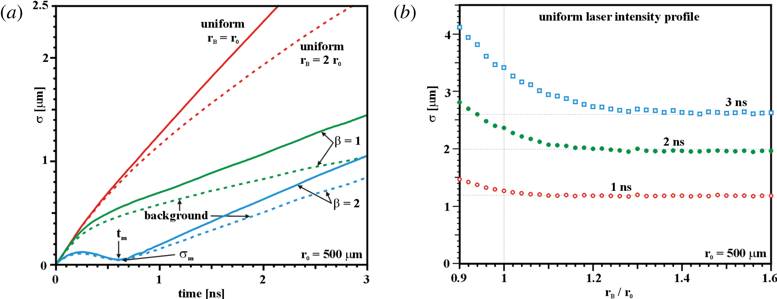
A similar set of hydrodynamic calculations has been performed in order to discriminate between the different laser profiles and to identify those that generate a shock wavefront as uniform as possible. The four laser intensity profiles given in figure 1 have been considered. In addition, two variant uniform laser intensity profiles have also been tested, one with a beam spot size equal to the initial capsule radius (
 $r_{B}=r_{0}$
, as in figure 2) and a second larger one in which the spot overfills the beam (
 $r_{B}=2r_{0}$
).
Plastic shell (
 $r_{0}=500~{\rm\mu}\text{m}$
) irradiated by a uniform laser intensity profile of radius
 $r_{B}=500~{\rm\mu}\text{m}$
. (a) Flow chart of the Lagrangian cell interfaces (
 $r_{Z=0}$
), r.m.s. non-uniformity
 ${\it\sigma}$
of the shock wavefront (solid line) and the oblateness factor
 ${\it\alpha}$
(dashed line) as a function of time. (b) Density map evaluated at time
 $t=2.5~\text{ns}$
and density profile (solid line) evaluated along the
 $Z$
-axis.

The temporal evolution of shock front non-uniformity is shown in figure 3(a). It is found that both laser shapes optimized by the illumination model provide better results in comparison with the uniform profiles. Moreover, when the background (55 % of the maximum intensity) is included, the shock front uniformity slightly improves compared to the case without background. It is found that the laser intensity profile optimized with
 ${\it\beta}=2$
provides better results in comparison to the case
 ${\it\beta}=1$
. This seems to indicate that the simple illumination of the sphere when the laser-to-capsule surfaces are coupled by the
 $\cos ^{2}$
function (
 ${\it\beta}=2$
) provides a better approximation of the laser energy deposition found by the hydrodynamic calculation. These optimal laser shapes calculated with
 ${\it\beta}=2$
assume a nearly ellipsoidal profile with an axis ratio of almost 1:2 and minor axis parallel to a meridian (figure 1
b,d). The observation that elliptical laser profiles produce better results than circular profiles has already been pointed out for both the Orion facility (Temporal et al.
Reference Temporal, Canaud, Garbett, Philippe and Ramis2013) and the LMJ (Temporal et al.
Reference Temporal, Canaud, Garbett and Ramis2014d
). Moreover, recent numerical calculations dedicated to the NIF facility seem to suggest the same conclusion (Weilacher et al.
Reference Weilacher, Radha, Collins and Marozas2015).
(a) Root-mean-square non-uniformity (
 ${\it\sigma}$
) of the shock wavefront as a function of time evaluated for different laser intensity profiles. (b) Shock wavefront non-uniformity evaluated at 1, 2 and 3 ns provided by the uniform intensity profiles as a function of the beam radius,
 $r_{B}/r_{0}$
.

The cases with uniform laser intensity profiles show worse results. It is also noted that a larger beam radius,
 $r_{B}=2r_{0}$
, produces lower shock front non-uniformity than when the spot is matched to the capsule size
 $r_{B}=r_{0}$
. Thus, for the uniform intensity profile, a larger beam radius is beneficial for decreasing the shock non-uniformity. This finding motivated another series of calculations where the beam radius was varied between
 $r=0.9r_{0}$
and
 $r=2r_{0}$
in order to analyse the effect of the beam size on the uniformity of the shock front. For these calculations the shock non-uniformities have been evaluated at times of 1, 2 and 3 ns. The corresponding results are shown in figure 3(b) as a function of the beam radius. First, it is found that a beam radius smaller than the capsule radius,
 $r<r_{0}$
, provides worse results and the effect is magnified at later times. In the opposite direction, for beam radii larger than a particular limit, around
 $1.2r_{0}$
, the calculations produce the same asymptotic non-uniformity. This indicates that when a background is considered – as for the laser profiles of figure 1(c,d) – the beam radius should be extended to about
 $1.2r_{0}$
. The use of a larger radius will not benefit the shock wave non-uniformity whilst it will be detrimental to the laser–capsule coupling efficiency. Further studies are required to fully understand this limit.
The results collected in figure 3(a) show that the best laser intensity profile is the one provided by the illumination model optimized with the parameter
 ${\it\beta}=2$
(figure 1
b). In this case the shock front non-uniformity exhibits a minimum
 ${\it\sigma}_{m}\approx 0.04~{\rm\mu}\text{m}$
at time
 $t_{m}\approx 600~\text{ps}$
, and, because of the nearly constant shock velocity
 $D=31.3~{\rm\mu}\text{m}~\text{ns}^{-1}$
, the distance travelled by the shock wave corresponds to about
 ${\it\delta}=Dt_{m}\approx 19~{\rm\mu}\text{m}$
.
In cryogenic direct drive ICF capsules an external shell – called the absorber – is usually present outside the solid fuel, specifically to improve laser energy deposition. Several considerations contribute to setting the thickness
 ${\it\delta}_{A}$
of the absorber. Generally, at the end of the laser pulse the mass of the absorber should be nearly completely ablated by the laser light in order to ensure near-optimal hydrodynamic efficiency of the implosion, in transferring momentum to the DT fuel payload. Another consideration relates to the stability of the imploding compressed shell, which is a function of the in-flight shell aspect ratio and so depends on the total remaining thickness of fuel and absorber. Here, we note that the minimum of the shock non-uniformity occurs at time
 $t_{m}$
, and this can also be used to set a constraint on
 ${\it\delta}_{A}$
based on uniformity requirements. In fact, if the distance travelled by the shock wave
 $({\it\delta}=Dt_{m})$
at time
 $t_{m}$
corresponds to the thickness of the absorber,
 ${\it\delta}_{A}={\it\delta}$
, then it follows that the shock transmitted to the fuel payload will initially be highly uniform. Although here we consider only the first shock from the early-time imprint phase, this shock provides a major contribution to the fuel adiabat and non-uniformity.
Different factors influence the distance
 ${\it\delta}$
, among them the absorbed power. In these calculations a constant absorbed power
 $P_{abs}=1~\text{TW}$
has been considered. Clearly, modifying the absorbed power
 $P_{abs}$
varies the distance
 ${\it\delta}$
, potentially allowing it to be tuned to the desired thickness of the absorber layer. If it is assumed that the shock velocity (
 $D$
) is proportional to the square root of the ablation pressure (
 $p$
) divided by the uncompressed plastic density (
 ${\it\rho}_{0}$
),
 $D{\it\alpha}[p/{\it\rho}_{0}]^{1/2}$
, and that for relatively small laser intensities
 $I$
the ablation pressure
 $p$
can be taken proportional to
 $I^{7/9}$
(Caruso & Gratton Reference Caruso and Gratton1968), then considering
 $I{\it\alpha}P_{abs}/r_{0}^{2}$
, where
 $r_{0}$
is the initial capsule radius, it follows that
 $D{\it\alpha}[P_{abs}/r_{0}^{2}]^{(7/18)}$
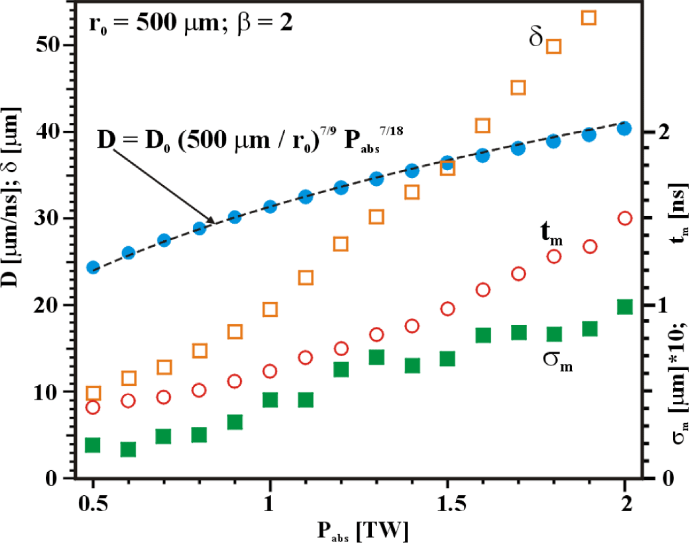
. A series of calculations have been performed varying the absorbed power,
 $P_{abs}$
, from 0.5 to 2 TW, thus providing the average shock wave velocity
 $D$
as a function of
 $P_{abs}$
. These results have been calculated for the capsule with radius
 $r_{0}=500~{\rm\mu}\text{m}$
and are collected in figure 4. Thus, it has been confirmed that the shock wave velocity scales reasonably well as
 $D=D_{0}[500~{\rm\mu}\text{m}/r_{0}]^{(7/9)}P_{abs}^{(7/18)}$
, with
 $D_{0}=31.3~{\rm\mu}\text{m}~\text{ns}^{-1}$
. In the same calculations the distances
 ${\it\delta}$
travelled by the shock wave at time
 $t_{m}$
corresponding to the minimum of the non-uniformity
 ${\it\sigma}_{m}$
have been determined. Figure 4 shows the distance
 ${\it\delta}$
, the time
 $t_{m}$
, and minimum non-uniformity
 ${\it\sigma}_{m}$
as a function of the absorbed power. It is found that the minimum in
 ${\it\sigma}$
appears at later times and assumes larger values when the absorbed power increases. Moreover, for this specific laser intensity profile and this capsule (
 $r_{0}=500~{\rm\mu}\text{m}$
), it is found that by modifying the absorbed power between 0.5 and 2 TW, the thickness
 ${\it\delta}$
of the plastic absorber crossed by the shock wave during the time
 $t_{m}$
can be varied between 10 and
 $60~{\rm\mu}\text{m}$
.
Average shock velocity
 $D$
(solid circles) and distance
 ${\it\delta}$
(empty squares) crossed by the shock wave at time
 $t_{m}$
(empty circles) when the shock wavefront non-uniformity assumes a local minimum,
 ${\it\sigma}_{m}$
(solid squares). These data are shown as a function of the absorbed power
 $P_{abs}$
and correspond to the capsule with radius
 $r_{0}=500~{\rm\mu}\text{m}$
and the optimal laser intensity profile of figure 2(b) calculated with
 ${\it\beta}=2$
.

4. Conclusion
The non-uniformity of the first shock wave generated by the direct irradiation of a spherical capsule has been analysed by means of two-dimensional hydrodynamic simulations. It has been assumed that two axisymmetric laser beams, located at co-latitudes 49° and 131°, irradiate a spherical plastic shell of thickness
 $100~{\rm\mu}\text{m}$
and external radius
 $r_{0}=500~{\rm\mu}\text{m}$
. This laser beam configuration has been chosen because it corresponds to the beams of the second cone of the Laser Mégajoule facility, which offer a potential route for fuel assembly in direct drive SI. Several laser intensity profiles have been considered. In all cases the laser absorbed power has been kept constant (
 $P_{abs}=1~\text{TW}$
) in order to generate the same shock velocity and allow consistent comparison of results. The target implosion is driven by a nearly spherical shock wave that travels inward at constant speed of around
 $D=31.3~{\rm\mu}\text{m}~\text{ns}^{-1}$
.
The non-uniformity of the shock front has been measured as a function of time. It has been found that the optimal laser intensity profile, solution of the original illumination model (
 ${\it\beta}=1$
), provides an r.m.s. shock front non-uniformity that grows considerably with time. This indicates that the pure illumination model does not adequately account for the laser-plasma coupling. As argued by Schmitt, a better solution could be obtained assuming a
 $\cos ^{2}$
relation (
 ${\it\beta}=2$
) between laser beam intensity and the target surface. Note that this also provides nearly elliptical spot solutions that are closer to the existing LMJ phase plates. It is found that this assumption provides laser intensity profiles that generate a much more uniform shock wavefront. In this case, the r.m.s. non-uniformity can be kept below
 $0.2~{\rm\mu}\text{m}$
over nearly the first ns. Moreover, the shock front non-uniformity is characterized by a minimum around the time
 $t_{m}=600~\text{ps}$
when the shock has travelled almost
 $20~{\rm\mu}\text{m}$
. This distance could be tuned by modifying the absorbed power, and it is argued that it could be used to set the thickness of the ablator in a standard direct drive ICF capsule. Indeed, in this case the transmitted shock to the DT payload will be highly uniform.
Acknowledgements
M.T. and B.C. express their thanks to D. Bouche for the support given to this work. M.T. would like to thank S. Atzeni for the DUED code. R.R. was partially supported by the EURATOM/CIEMAT association in the framework of the ‘IFE Keep-in-Touch Activities’.