1 Introduction
For several decades, one of the principal ways of fuelling magnetically confined fusion plasmas has been to inject pellets consisting of frozen hydrogen (or deuterium). This method has several attractions compared with other fuelling schemes. Unlike neutral-beam injection, it is independent of the heating of the plasma, and compared with gas puffing it provides fuelling relatively deep into the plasma.
There are many intricate issues to consider when modelling pellets in fusion plasmas, such as the ablation of the solid pellet material leading to the formation of a cold plasma cloud that acts to shield the pellet; the expansion of this cloud along the magnetic field; its drift across the field; the associated emission of Alfvén waves; striations and instabilities of the pellet cloud etc. A large body of literature discusses these issues, both experimentally and theoretically, and several reviews have been published on the subject (Milora et al. Reference Milora, Houlberg, Lengyel and Mertens1995; Pégourié Reference Pégourié2007).
In the present work, we would like to raise attention to a phenomenon that appears to have been overlooked in earlier modelling of plasmas with pellet injection but which can be quite important when the electron and ion temperatures are unequal. Pellets are, of course, injected to increase the plasma density, but as we shall see they can also affect the relative electron/ion energy budget significantly. The reason is simple and relies on a well-known circumstance: when a cold plasma cloud, in our case coming from a pellet, expands into a region of lower density, the electrons, being more mobile than the ions, pull the latter with them by setting up an ambipolar electric field which accelerates the ions. In this way, thermal electron energy is converted into kinetic ion energy. This energy ends up as ion thermal energy after a few ion collision times as the pellet cloud dissolves and merges with the background plasma. The resulting electron–ion energy transfer can easily compete with collisional temperature equilibration and thus significantly affects the energy budget and transport of the plasma.
2 Model description and simple estimates
When a small dense pellet enters the plasma only a thin layer is heated and evaporated by the plasma heat flux. The width of this layer is approximately equal to the mean free path of the hot plasma electrons in the pellet (
 $\unicode[STIX]{x1D706}_{p}$
). This evaporated over-dense gas cloud initially expands with the ion sound speed in three dimensions while its hydrodynamic pressure is much greater than the magnetic pressure,
 $$\begin{eqnarray}\frac{3NT}{4\unicode[STIX]{x03C0}r^{3}}\gg \frac{B^{2}}{2\unicode[STIX]{x1D707}_{0}},\end{eqnarray}$$
where
 $B$
is the magnetic field and
 $r$
,
 $N$
and
 $T$
are the cloud size, number of evaporated electrons and their temperature, respectively. During this three-dimensional expansion the cloud line-integrated density (along the magnetic field line) decreases and the hot plasma reaches new layers of the pellet. It is essential that the fast expansion of the cloud across the magnetic field eventually stops when expression (2.1) becomes an equality. Then, the cloud continues to expand only along the magnetic field line.
As mentioned above, an accurate description the ablation process is generally more complex. However, in what follows we focus only on the one-dimensional expansion dynamics of the cloud along the magnetic field, which follows the ablation process. We also neglect the cross-field drift of the polarised cloud in the non-uniform magnetic field. This effect can be important in tokamaks (Parks & Baylor Reference Parks and Baylor2005; Pégourié et al. Reference Pégourié, Waller, Nehme, Garzotti and Géraud2006), but is generally much weaker in stellarators.
We thus consider a relatively small and dense cloud of the cold plasma at some initial time
 $t=0$
. This cloud is heated by collisions from the electrons of the hot ambient plasma. Since the line-integrated cloud density can only be lower (mainly due to initial spherical expansion) than the one defined by
 $\unicode[STIX]{x1D706}_{p}$
during the ablation, the collisional mean free path of hot electrons in the cloud is comparable to, or exceeds, the length of the plasma cloud. In other words the pellet cloud is typically ‘transparent’ for the hot electrons throughout the entire expansion process. Then, in the limit that the cloud is much colder than the hot electrons, the heating power density is equal to
 $$\begin{eqnarray}Q=\frac{3n_{e}T_{e}}{2\unicode[STIX]{x1D70F}_{ec}},\end{eqnarray}$$
where
 $$\begin{eqnarray}\unicode[STIX]{x1D70F}_{ec}=\left.\frac{3\sqrt{\unicode[STIX]{x03C0}}}{4}\right/\frac{n_{c}\text{e}^{4}\ln \unicode[STIX]{x1D6EC}}{4\unicode[STIX]{x03C0}\unicode[STIX]{x1D716}_{0}^{2}m_{e}^{2}v_{Te}^{3}}=\frac{n_{e}\unicode[STIX]{x1D70F}_{ee}}{n_{c}}\end{eqnarray}$$
denotes the collision time between fast and slow electrons. In these and subsequent equations, a subscript
 $c$
refers to the cold electrons of the pellet ablation cloud and the subscript
 $e$
to the hot electrons of the ambient plasma. The density of the former is initially much larger than that of the latter,
 $n_{c}\gg n_{e}$
, but drops as the cloud expands. The thermal speed of the cold electrons is denoted by
 $v_{Tc}=(2T_{c}/m_{e})^{1/2}$
and their temperature by
 $T_{c}$
. This temperature and length of the cloud initially evolve approximately according to
 $$\begin{eqnarray}\displaystyle & \displaystyle T_{c}(t)\sim \frac{T_{e}t}{\unicode[STIX]{x1D70F}_{ee}}, & \displaystyle\end{eqnarray}$$
 $$\begin{eqnarray}\displaystyle & \displaystyle L(t)\sim v_{Te}\sqrt{\frac{m_{e}t^{3}}{m_{i}\unicode[STIX]{x1D70F}_{ee}}}, & \displaystyle\end{eqnarray}$$
where the latter estimate follows from the fact that the cloud expands at the sound speed (
 $c_{s}$
), which is of order
 $v_{Te}\sqrt{m_{e}/m_{i}}$
. The density of cold electrons in the cloud thus decreases with time as
 $$\begin{eqnarray}n_{c}\sim n_{\infty }\left(\frac{\unicode[STIX]{x1D70F}_{ee}}{t}\right)^{3/2},\end{eqnarray}$$
where
 $n_{\infty }$
is a constant related to the total number of electrons in the cloud. We restrict our attention to early times at which the cloud is denser than the ambient plasma,
 $n_{c}\gg n_{e}$
, and thus require
 $$\begin{eqnarray}\frac{t}{\unicode[STIX]{x1D70F}_{ee}}\ll \left(\frac{n_{\infty }}{n_{e}}\right)^{2/3}.\end{eqnarray}$$
At the time of electron temperature equilibration,
 $t=\unicode[STIX]{x1D70F}_{ee}$
, the cloud has reached the length
 $$\begin{eqnarray}L_{\infty }\sim \unicode[STIX]{x1D706}_{ee}\sqrt{\frac{m_{e}}{m_{i}}},\end{eqnarray}$$
where
 $\unicode[STIX]{x1D706}_{ee}=v_{Te}\unicode[STIX]{x1D70F}_{ee}$
denotes the mean free path of the background plasma. For simplicity, we take the number on the right-hand side of (2.7) to be of order unity, so that the density of the cloud reaches the background density at around the same time as the temperatures equilibrate.
The mean free path of the cold electrons is
 $\unicode[STIX]{x1D706}_{c}=v_{Tc}\unicode[STIX]{x1D70F}_{cc}$
where
 $$\begin{eqnarray}\displaystyle & \displaystyle v_{Tc}=v_{Te}\sqrt{\frac{T_{c}}{T_{e}}}, & \displaystyle\end{eqnarray}$$
 $$\begin{eqnarray}\displaystyle & \displaystyle \unicode[STIX]{x1D70F}_{cc}=\unicode[STIX]{x1D70F}_{ee}\frac{n_{e}}{n_{c}}\left(\frac{T_{c}}{T_{e}}\right)^{3/2}. & \displaystyle\end{eqnarray}$$
Combining these estimates gives the relations
 $$\begin{eqnarray}\displaystyle & \displaystyle \frac{t}{\unicode[STIX]{x1D70F}_{cc}}\sim \frac{n_{\infty }}{n_{e}}\left(\frac{\unicode[STIX]{x1D70F}_{ee}}{t}\right)^{2}, & \displaystyle\end{eqnarray}$$
 $$\begin{eqnarray}\displaystyle & \displaystyle \frac{\unicode[STIX]{x1D706}_{c}}{L}\sim \sqrt{\frac{m_{i}}{m_{e}}}\frac{n_{e}}{n_{\infty }}\left(\frac{t}{\unicode[STIX]{x1D70F}_{ee}}\right)^{2}, & \displaystyle\end{eqnarray}$$
which allow us to identify two time regimes characterised by different degrees of collisionality. At early times,
 $$\begin{eqnarray}\frac{t}{\unicode[STIX]{x1D70F}_{ee}}\ll \sqrt{\frac{n_{\infty }}{n_{e}}}\left(\frac{m_{e}}{m_{i}}\right)^{1/4},\end{eqnarray}$$
the mean free path is shorter than the length of the cloud, which is highly collisional and can be described by hydrodynamic (Braginskii) equations. At later times,
 $$\begin{eqnarray}\sqrt{\frac{n_{\infty }}{n_{e}}}\left(\frac{m_{e}}{m_{i}}\right)^{1/4}\ll \frac{t}{\unicode[STIX]{x1D70F}_{ee}}\ll \sqrt{\frac{n_{\infty }}{n_{e}}},\end{eqnarray}$$
the mean free path is longer than the cloud, which however expands slowly on the time scale of collisions between the cold electrons.
3 Equations for the cloud dynamics
In order to treat both early and later time regimes (2.13) and (2.14), we consider the kinetic equation for the cloud electrons
 $$\begin{eqnarray}\frac{\unicode[STIX]{x2202}f}{\unicode[STIX]{x2202}t}+v_{\Vert }\frac{\unicode[STIX]{x2202}f}{\unicode[STIX]{x2202}x}+\frac{e}{m_{e}}\frac{\unicode[STIX]{x2202}\unicode[STIX]{x1D719}}{\unicode[STIX]{x2202}x}\frac{\unicode[STIX]{x2202}f}{\unicode[STIX]{x2202}v_{\Vert }}=C(f),\end{eqnarray}$$
where
 $\unicode[STIX]{x1D719}$
denotes the electrostatic potential,
 $C$
the collision operator and
 $-e$
the electron charge. For simplicity we have dropped the subscript
 $c$
, adopting the convention that quantities without subscript refer to the cold electrons. The components of the particle velocity along and across the magnetic field, respectively, are denoted by
 $v_{\Vert }$
and
 $v_{\bot }$
, and the speed by
 $v=\sqrt{v_{\Vert }^{2}+v_{\bot }^{2}}$
. It is helpful to replace the velocity coordinate by the energy
 $\unicode[STIX]{x1D716}=m_{e}v^{2}/2-e\unicode[STIX]{x1D719}$
, so that the kinetic equation becomes
 $$\begin{eqnarray}\frac{\unicode[STIX]{x2202}f}{\unicode[STIX]{x2202}t}+v_{\Vert }\frac{\unicode[STIX]{x2202}f}{\unicode[STIX]{x2202}x}-e\frac{\unicode[STIX]{x2202}\unicode[STIX]{x1D719}}{\unicode[STIX]{x2202}t}\frac{\unicode[STIX]{x2202}f}{\unicode[STIX]{x2202}\unicode[STIX]{x1D716}}=C_{cc}(f)+C_{ce}(f),\end{eqnarray}$$
where we have now written the collision operator as a sum of an operator describing collisions among the cold particles and a term representing collisions with the hot electrons, which heat the cloud. The time derivatives in this equation operate on the time scale of the expansion of the cloud, which is comparable to the heating rate (described by
 $C_{ce}$
) but much slower than the electron thermal speed. We thus expand the distribution accordingly,
 $f=f_{0}+f_{1}+\cdots \,,$
and require in lowest order
 $$\begin{eqnarray}v_{\Vert }\left(\frac{\unicode[STIX]{x2202}f_{0}}{\unicode[STIX]{x2202}x}\right)_{\unicode[STIX]{x1D716},v_{\bot },t}=C_{cc}(f_{0}).\end{eqnarray}$$
In order to account for the circumstance that the mean free path can be either shorter or longer than the cloud, we have adopted a ‘maximal’ ordering and retained the cold-electron collision operator in this equation. In contrast, the well-known work by Gurevich (Gurevich Reference Gurevich1968) considered the completely collisionless case.
Multiplying (3.3) by
 $\ln f_{0}$
and integrating over all of phase space gives
 $$\begin{eqnarray}\int _{-\infty }^{\infty }\,\text{d}x\int C_{cc}(f_{0})\ln f_{0}\,\text{d}^{3}v=0,\end{eqnarray}$$
which together the H-theorem implies that
 $f_{0}$
must be Maxwellian,
 $$\begin{eqnarray}f_{0}(\unicode[STIX]{x1D716},t)=\unicode[STIX]{x1D702}(t)\left[\frac{m_{e}}{2\unicode[STIX]{x03C0}T(t)}\right]^{3/2}\text{e}^{-\unicode[STIX]{x1D716}/T(t)},\end{eqnarray}$$
and the cold-electron density thus follows a Boltzmann distribution,
 $$\begin{eqnarray}n(x,t)=\unicode[STIX]{x1D702}(t)\exp \left(\frac{e\unicode[STIX]{x1D719}(x,t)}{T(t)}\right).\end{eqnarray}$$
The ions are much colder than the electrons, and can be treated by pressureless hydrodynamic equations
 $$\begin{eqnarray}\displaystyle & \displaystyle \frac{\unicode[STIX]{x2202}n}{\unicode[STIX]{x2202}t}+\frac{\unicode[STIX]{x2202}}{\unicode[STIX]{x2202}x}(nu)=0, & \displaystyle\end{eqnarray}$$
 $$\begin{eqnarray}\displaystyle & \displaystyle m_{i}\left(\frac{\unicode[STIX]{x2202}u}{\unicode[STIX]{x2202}t}+u\frac{\unicode[STIX]{x2202}u}{\unicode[STIX]{x2202}x}\right)=-e\frac{\unicode[STIX]{x2202}\unicode[STIX]{x1D719}}{\unicode[STIX]{x2202}x}, & \displaystyle\end{eqnarray}$$
where, thanks to the Boltzmann relation (3.6) and assuming quasi-neutralityFootnote 1 , the electric force term can be replaced by
 $$\begin{eqnarray}-e\frac{\unicode[STIX]{x2202}\unicode[STIX]{x1D719}}{\unicode[STIX]{x2202}x}=-T(t)\frac{\unicode[STIX]{x2202}\ln n}{\unicode[STIX]{x2202}x}.\end{eqnarray}$$
The cold-electron temperature
 $T$
is independent of
 $x$
but increases with time in response to the heating, according the energy conservation relation
 $$\begin{eqnarray}\frac{\text{d}}{\text{d}t}\int _{-\infty }^{\infty }\left(\frac{3nT}{2}+\frac{m_{i}nu^{2}}{2}\right)\,\text{d}x=\int _{-\infty }^{\infty }Q\,\text{d}x,\end{eqnarray}$$
where the heating source is given by
 $$\begin{eqnarray}Q(x,t)=\int \frac{m_{e}v^{2}}{2}C_{ce}(f_{0})\,\text{d}^{3}v.\end{eqnarray}$$
When
 $T(t)=\text{const}.$
equations (3.7)–(3.10) represent a classical isothermal hydrodynamics system of equations, sometimes called the ‘shallow water equations’. Depending on the initial and boundary conditions, this nonlinear system permits a wide range of solutions, including wave and shock wave type solutions (Gurevich & Pitaevskii Reference Gurevich, Pitaevskii and Leontovich1986). In the next section we suggest a monotonic (on the half-axis) self-similar solution which approximates expansion of a gradually headed plasma. This kind of self-similar plasma expansion differs from other well-known solutions such as the Sedov–Taylor–von Neumann blast wave (Barenblatt Reference Barenblatt1996) or plasma expansion into a vacuum (Gurevich, Pariǐskaya & Pitaevskiǐ Reference Gurevich, Pariǐskaya and Pitaevskiǐ1966), where the temperature of the hot plasma, which initially occupies a half-space, is fixed.
4 Self-similar solutions
We look for solutions to the equations (3.7)–(3.10) with the initial conditions
 $$\begin{eqnarray}\displaystyle & \displaystyle n(x,0)=n_{0}\unicode[STIX]{x1D6FF}(x), & \displaystyle\end{eqnarray}$$
 $$\begin{eqnarray}\displaystyle & \displaystyle n(x,0)u(x,0)=0, & \displaystyle\end{eqnarray}$$
 $$\begin{eqnarray}\displaystyle & \displaystyle T(x,0)=0, & \displaystyle\end{eqnarray}$$
reflecting the circumstance that the cloud is initially very dense, small, stationary and cold. This initial-value problem contains no inherent length scale and its solution must therefore be self-similar. We therefore introduce a variable
 $$\begin{eqnarray}y=\frac{x}{t^{\unicode[STIX]{x1D6FC}}},\end{eqnarray}$$
where the constant
 $\unicode[STIX]{x1D6FC}$
is to be determined, and look for solutions of the form
 $$\begin{eqnarray}\left.\begin{array}{@{}c@{}}\displaystyle n(x,t)=t^{-\unicode[STIX]{x1D6FC}}N(y),\\ \displaystyle u(x,t)=t^{-\unicode[STIX]{x1D6FD}}U(y),\\ T(t)=t^{-\unicode[STIX]{x1D6FE}}\unicode[STIX]{x1D70F},\end{array}\right\}\end{eqnarray}$$
where the first expression manifestly implies mass conservation,
 $$\begin{eqnarray}\frac{\text{d}}{\text{d}t}\int _{-\infty }^{\infty }n(x,t)\,\text{d}x=0.\end{eqnarray}$$
Substituting this ansatz into the continuity equation (3.7), momentum equation (3.8) and energy equation (3.10) gives equations that imply that
 $\unicode[STIX]{x1D6FC}=3/2$
,
 $\unicode[STIX]{x1D6FD}=-1/2$
, and
 $\unicode[STIX]{x1D6FE}=-1$
and the equations themselves reduce to
 $$\begin{eqnarray}\displaystyle & \displaystyle {\textstyle \frac{3}{2}}(yN)^{\prime }=(NU)^{\prime }, & \displaystyle\end{eqnarray}$$
 $$\begin{eqnarray}\displaystyle & \displaystyle m_{i}N(U-3yU^{\prime }+2UU^{\prime })+2N^{\prime }\unicode[STIX]{x1D70F}=0, & \displaystyle\end{eqnarray}$$
 $$\begin{eqnarray}\displaystyle & \displaystyle \int _{-\infty }^{\infty }\left(\frac{3N\unicode[STIX]{x1D70F}}{2}+\frac{m_{i}NU^{2}}{2}\right)\,\text{d}y=\int _{-\infty }^{\infty }Q\,\text{d}x. & \displaystyle\end{eqnarray}$$
The solutions to these equations are
 $$\begin{eqnarray}\displaystyle & \displaystyle N(y)=n_{0}\sqrt{\frac{3m_{i}}{8\unicode[STIX]{x03C0}\unicode[STIX]{x1D70F}}}\exp \left(-\frac{3m_{i}y^{2}}{8\unicode[STIX]{x1D70F}}\right), & \displaystyle\end{eqnarray}$$
 $$\begin{eqnarray}\displaystyle & \displaystyle U(y)=\frac{3y}{2}, & \displaystyle\end{eqnarray}$$
 $$\begin{eqnarray}\displaystyle & \displaystyle \unicode[STIX]{x1D70F}=\frac{1}{3n_{0}}\int _{-\infty }^{\infty }Q\,\text{d}x, & \displaystyle\end{eqnarray}$$
and we thus conclude that the plasma parameters become
 $$\begin{eqnarray}\displaystyle & \displaystyle n(x,t)=n_{0}\sqrt{\frac{3m_{i}}{8\unicode[STIX]{x03C0}\unicode[STIX]{x1D70F}t^{3}}}\exp \left(-\frac{3m_{i}x^{2}}{8\unicode[STIX]{x1D70F}t^{3}}\right), & \displaystyle\end{eqnarray}$$
 $$\begin{eqnarray}\displaystyle & \displaystyle u(x,t)=\frac{3x}{2t}, & \displaystyle\end{eqnarray}$$
 $$\begin{eqnarray}\displaystyle & \displaystyle T(t)=\frac{t}{3n_{0}}\int _{-\infty }^{\infty }Q\,\text{d}x. & \displaystyle\end{eqnarray}$$
Note that the temperature is half of what it would have been if the pellet cloud were stationary (obtained by setting
 $u=0$
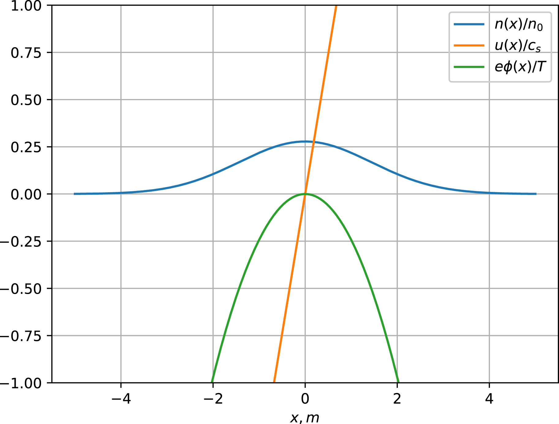
in (3.10)). Half the heating power evidently goes into ion kinetic energy associated with the expansion of the cloud. Figure 1 illustrates the solution (4.13)–(4.14).
The normalised cloud density (
 $n/n_{0}$
), ion velocity (
 $u/c_{s}$
) and potential (
 $e\unicode[STIX]{x1D719}/T$
) from the solution (4.13)–(4.15) in the early stage of expansion
 $t\approx 10~\unicode[STIX]{x03BC}\text{s}\approx \unicode[STIX]{x1D70F}_{ee}/20$
. The ambient electron temperature is 4 keV and the ultimate cloud density equals the initial plasma density of
 $5\times 10^{19}~\text{m}^{-3}$
(doubling the density on the field line after expansion).

Note also that the potential
 $\unicode[STIX]{x1D719}$
resulting from this solution monotonically decreases to minus infinity. Physically it is more reasonable to expect that it saturates at a finite value, in which case the ion velocity
 $u$
becomes limited and the tail of the ion distribution exhibits a sharp front (see Gurevich & Pitaevskii Reference Gurevich, Pitaevskii and Leontovich1986; Mora Reference Mora2003). We neglect these subtleties in this work.
Our choice of a delta function for the initial condition is of course not to be taken literally in the sense that the initial density is actually infinite, only that it is very large. We have also solved (3.7)–(3.10) numerically with other initial conditions and seen that the solution converges to ours as
 $t\rightarrow \infty$
. It is typical for self-similar solutions to act as ‘attractors’ in this way in the larger space of other solutions.
5 Very early times: collisional electrons
The ordering leading up to solution (4.13)–(4.15) fails in the very early phase of the cloud expansion, which we now discuss separately. At early times defined by (2.13), the electrons are collisional and the pellet cloud can thus be described by hydrodynamic equations,
 $$\begin{eqnarray}\displaystyle & \displaystyle \frac{\unicode[STIX]{x2202}n}{\unicode[STIX]{x2202}t}+\frac{\unicode[STIX]{x2202}}{\unicode[STIX]{x2202}x}(nu)=0, & \displaystyle\end{eqnarray}$$
 $$\begin{eqnarray}\displaystyle & \displaystyle m_{i}n\left(\frac{\unicode[STIX]{x2202}u}{\unicode[STIX]{x2202}t}+u\frac{\unicode[STIX]{x2202}u}{\unicode[STIX]{x2202}x}\right)=-\frac{\unicode[STIX]{x2202}}{\unicode[STIX]{x2202}x}(nT), & \displaystyle\end{eqnarray}$$
 $$\begin{eqnarray}\displaystyle & \displaystyle \frac{3}{2}\left(\frac{\unicode[STIX]{x2202}T}{\unicode[STIX]{x2202}t}+u\frac{\unicode[STIX]{x2202}T}{\unicode[STIX]{x2202}x}\right)+T\frac{\unicode[STIX]{x2202}u}{\unicode[STIX]{x2202}x}=\frac{1}{n}\frac{\unicode[STIX]{x2202}}{\unicode[STIX]{x2202}x}\left(\unicode[STIX]{x1D705}\frac{\unicode[STIX]{x2202}T}{\unicode[STIX]{x2202}x}\right)+\frac{Q}{n}. & \displaystyle\end{eqnarray}$$
Here, viscosity has been neglected, being relatively small when the mean free path is short, but heat conduction has been retained. The heat conductivity
 $\unicode[STIX]{x1D705}/n\sim v_{c}\unicode[STIX]{x1D70F}_{cc}$
is unimportant if the time scale of heat conduction
 $$\begin{eqnarray}t_{\text{cond}}\sim \frac{L^{2}}{\unicode[STIX]{x1D705}/n}\end{eqnarray}$$
is longer than
 $t$
. This is the case if
 $$\begin{eqnarray}\frac{t}{\unicode[STIX]{x1D70F}_{ee}}\ll \sqrt{\frac{n_{\infty }}{n_{e}}\frac{m_{e}}{m_{i}}},\end{eqnarray}$$
and we thus conclude that heat conduction can be neglected at very early times. This means that the pellet cloud will not be isothermal unless the heating source is uniform. As discussed in § 2, a uniform heating source is expected because the mean free path of the fast electrons is typically longer than the length of the pellet cloud. Nevertheless, it turns out that half the heating power is still deposited in the ion channel even in the opposite case of a short mean free path of the ambient electrons in the cloud. The reason is essentially that the heating profile is dictated by this mean free path, which evolves in inverse proportion to the cloud density and therefore evolves in a self-similar fashion, just like all the other cloud parameters.
To see this, let us consider the kinetic equation for the distribution function
 $f_{e}$
of the fast electrons,
 $$\begin{eqnarray}v_{\Vert }\frac{\unicode[STIX]{x2202}f_{e}}{\unicode[STIX]{x2202}x}+\frac{e}{m_{e}}\frac{\unicode[STIX]{x2202}\unicode[STIX]{x1D719}}{\unicode[STIX]{x2202}x}\frac{\unicode[STIX]{x2202}f_{e}}{\unicode[STIX]{x2202}v_{\Vert }}=C(f_{e}),\end{eqnarray}$$
where the time derivative has been neglected on the grounds that the thermal electron speed exceeds the expansion velocity of the cloud. As long as the cloud plasma is much denser and colder than the population of fast electrons, the collision operator is well approximated by
 $$\begin{eqnarray}C(f_{e})=\frac{n\text{e}^{4}\ln \unicode[STIX]{x1D6EC}}{3\unicode[STIX]{x03C0}^{3/2}\unicode[STIX]{x1D716}_{0}^{2}m_{e}^{2}}\left[\frac{1+Z}{v^{3}}{\mathcal{L}}(f_{e})+\frac{1}{v^{2}}\frac{\unicode[STIX]{x2202}f_{e}}{\unicode[STIX]{x2202}v}\right],\end{eqnarray}$$
representing slowing down and pitch-angle scattering against cold electrons and ions of effective charge
 $Z$
.
If we again introduce the self-similar variable (4.4) and write the density as in (4.5) we find
 $$\begin{eqnarray}v_{\Vert }\frac{\unicode[STIX]{x2202}f_{e}}{\unicode[STIX]{x2202}y}+\frac{e}{m_{e}}\frac{\unicode[STIX]{x2202}\unicode[STIX]{x1D719}}{\unicode[STIX]{x2202}y}\frac{\unicode[STIX]{x2202}f_{e}}{\unicode[STIX]{x2202}v_{\Vert }}=N(y)\frac{\text{e}^{4}\ln \unicode[STIX]{x1D6EC}}{3\unicode[STIX]{x03C0}^{3/2}\unicode[STIX]{x1D716}_{0}^{2}m_{e}^{2}}\left[\frac{1+Z}{v^{3}}{\mathcal{L}}(f_{e})+\frac{1}{v^{2}}\frac{\unicode[STIX]{x2202}f_{e}}{\unicode[STIX]{x2202}v}\right],\end{eqnarray}$$
and conclude that the distribution function can be written as a function of
 $y$
and
 $\boldsymbol{v}$
alone,
 $$\begin{eqnarray}f_{e}(x,v_{\Vert },v_{\bot },t)=F(y,v_{\Vert },v_{\bot }).\end{eqnarray}$$
The physical reason for this conclusion is that, since the collision operator is proportional to the density
 $n(x,t)=N(y)/t^{\unicode[STIX]{x1D6FC}}$
, the distribution function depends on
 $x$
and
 $t$
only through the similarity variable
 $y=x/t^{\unicode[STIX]{x1D6FC}}$
. The same is then true for the heating per particle
 $$\begin{eqnarray}h(y)=-\frac{1}{n}\int \frac{m_{e}v^{2}}{2}C(f_{e})\,\text{d}^{3}v,\end{eqnarray}$$
which, in turn, implies that the system of equations
 $$\begin{eqnarray}\displaystyle & \displaystyle {\textstyle \frac{3}{2}}(N+yN^{\prime })=(NU)^{\prime }, & \displaystyle\end{eqnarray}$$
 $$\begin{eqnarray}\displaystyle & \displaystyle m_{i}N\left(\frac{U}{2}-\frac{3y}{2}U^{\prime }+UU^{\prime }\right)=-(N\unicode[STIX]{x1D70F})^{\prime }, & \displaystyle\end{eqnarray}$$
 $$\begin{eqnarray}\displaystyle & \displaystyle \frac{3}{2}\left(\unicode[STIX]{x1D70F}-\frac{3y}{2}\unicode[STIX]{x1D70F}^{\prime }+U\unicode[STIX]{x1D70F}^{\prime }\right)+\unicode[STIX]{x1D70F}U^{\prime }=h, & \displaystyle\end{eqnarray}$$
can be solved for
 $N(y)$
,
 $U(y)=t^{-1/2}u(y,t)$
and
 $\unicode[STIX]{x1D70F}(y)=t^{-1}T(y,t)$
as functions of
 $y$
alone. The first of these equations is, again, satisfied by
 $U(y)=3y/2$
, and the other two equations then become
 $$\begin{eqnarray}\left.\begin{array}{@{}c@{}}3m_{i}yN+4(N\unicode[STIX]{x1D70F})^{\prime }=0,\\ \displaystyle \unicode[STIX]{x1D70F}=\frac{h}{3}.\end{array}\right\}\end{eqnarray}$$
To calculate the expansion of the pellet cloud, one needs to solve these equations together with (5.8). In general, the density profile will no longer be Gaussian, but thanks to (5.14) we can conclude that, for any shape
 $N(y)$
of the cloud, the electron temperature is always given by
 $$\begin{eqnarray}T(x,t)=\frac{t}{3}h\left(\frac{x}{t^{3/2}}\right).\end{eqnarray}$$
The total thermal energy of the cloud electrons is thus equal to
 $$\begin{eqnarray}\int _{-\infty }^{\infty }\frac{3nT}{2}\,\text{d}x=\frac{t}{2}\int _{-\infty }^{\infty }N(y)h(y)\,\text{d}y.\end{eqnarray}$$
On the other hand, the net energy budget of the system (5.1)–(5.3) is given by
 $$\begin{eqnarray}\frac{\text{d}}{\text{d}t}\int _{-\infty }^{\infty }\left(\frac{3nT}{2}+\frac{m_{i}nv^{2}}{2}\right)\,\text{d}x=\int _{-\infty }^{\infty }nh\,\text{d}x=\int _{-\infty }^{\infty }Nh\,\text{d}y,\end{eqnarray}$$
which implies that half the heating power goes into increasing the electron temperature while the other half goes into the ion channel.
6 Ion heating
This kinetic energy will eventually (after a few ion collision times) end up as thermal ion energy. The time scale of electron–ion temperature equilibration is relatively long compared with both the electron collision time and the ion–ion collision time,
 $\unicode[STIX]{x1D70F}_{\text{eq}}\sim \unicode[STIX]{x1D70F}_{ee}m_{i}/m_{e}\sim \unicode[STIX]{x1D70F}_{ii}\sqrt{m_{i}/m_{e}}$
, and the kinetic energy of the pellet ions will therefore be converted into ion thermal energy before being shared with the electrons.
In plasmas with dominant electron heating, the steady-state ion temperature is typically determined by the ratio of the energy confinement time (
 $\unicode[STIX]{x1D70F}_{\unicode[STIX]{x1D700}}$
) to the equilibration time
 $\unicode[STIX]{x1D70F}_{\text{eq}}$
(assumed to be longer)
 $$\begin{eqnarray}T_{i}\sim T_{e}\frac{\unicode[STIX]{x1D70F}_{\unicode[STIX]{x1D700}}}{\unicode[STIX]{x1D70F}_{\text{eq}}}.\end{eqnarray}$$
In such a case, the fast electron-to-ion energy transfer through ambipolar expansion may increase the ion temperature considerably.
If pellets are injected to keep the density constant, then the amount of injected pellet material per unit time is
 $n/\unicode[STIX]{x1D70F}_{n}$
, where
 $\unicode[STIX]{x1D70F}_{n}$
is the particle confinement time. The pellet ions are quickly accelerated to roughly
 $T_{e}$
via ambipolar expansion. The resulting power deposition per ion is then
 $T_{e}/\unicode[STIX]{x1D70F}_{n}$
, which modifies (6.1) to
 $$\begin{eqnarray}T_{i}\sim T_{e}\unicode[STIX]{x1D70F}_{\unicode[STIX]{x1D700}}\left(\frac{1}{\unicode[STIX]{x1D70F}_{\text{eq}}}+\frac{1}{\unicode[STIX]{x1D70F}_{n}}\right),\end{eqnarray}$$
where the two terms in the brackets can be comparable, as discussed in the next section.
The net effect of a single pellet on time scales exceeding the ion collision time but shorter than the equilibration time is an increase in density, cooling of the electrons and heating of the ions. If we denote the plasma density before the injection by
 $n$
and that afterwards by
 $n+dn$
, and adopt similar notation for the electron and ion temperatures, the change in the ion and electron energies are, respectively,
 $$\begin{eqnarray}\displaystyle & \displaystyle \unicode[STIX]{x0394}W_{i}={\textstyle \frac{3}{2}}(T_{i}\,\text{d}n+n\,\text{d}T_{i}), & \displaystyle\end{eqnarray}$$
 $$\begin{eqnarray}\displaystyle & \displaystyle \unicode[STIX]{x0394}W_{e}={\textstyle \frac{3}{2}}(T_{e}\,\text{d}n+n\,\text{d}T_{e}). & \displaystyle\end{eqnarray}$$
During the short time scale on which a pellet is injected, evaporates and merges with the background plasma, the total plasma energy is conserved,
 $\text{d}W_{i}+\text{d}W_{e}=0$
, if ionisation and radiation losses are negligible. We thus have
 $$\begin{eqnarray}\frac{\text{d}T_{e}+\text{d}T_{i}}{T_{e}+T_{i}}=-\frac{\text{d}n}{n}.\end{eqnarray}$$
The electrons lose, and the ions gain, energy,
 $\text{d}W_{e}<0<\text{d}W_{i}$
. As we have seen, the energy transferred to the ions is equal to that expended in heating the pellet electrons, so that
 $$\begin{eqnarray}\text{d}W_{i}=\frac{3\unicode[STIX]{x1D6FC}}{2}T_{e}\,\text{d}n,\end{eqnarray}$$
with
 $\unicode[STIX]{x1D6FC}\simeq 1$
. (A different value of
 $\unicode[STIX]{x1D6FC}$
would allow for the possibility that more or less energy is channelled to the ions.) Hence, to first order in the perturbation
 $\text{d}n/n\ll 1$
,
 $$\begin{eqnarray}\text{d}T_{i}=\frac{\text{d}n}{n}(\unicode[STIX]{x1D6FC}T_{e}-T_{i}),\end{eqnarray}$$
and the corresponding drop in electron temperature calculated from (6.5) becomes
 $$\begin{eqnarray}\text{d}T_{e}=-\frac{\text{d}n}{n}[(1+\unicode[STIX]{x1D6FC})T_{e}].\end{eqnarray}$$
We thus conclude that the electrons are cooled by pellet injection whereas the ions are heated if
 $T_{e}>T_{i}$
. As far as we are aware, this heating has usually been neglected in transport modelling of magnetically confined fusion plasmas. The increased density caused by pellet injection has simply been modelled as a dilution of the background plasma at constant energy in each channel, thus leading to cooling of both the electrons and the ions.
The analytical solution of the cloud expansion process presented in § 4 could help to improve the modelling of pellets in three-dimensional magnetohydrodynamics (MHD) codes, such as JOREK (Futatani et al. Reference Futatani, Huijsmans, Loarte, Baylor, Commaux, Jernigan, Fenstermacher, Lasnier, Osborne and Pegourié2014). Such codes, which solve a set of one- (or two-) fluid equations, are not able to accurately describe a pellet cloud, and the numerical (toroidal) resolution is usually so low that it is difficult to simulate the initial phase of the cloud expansion.
It is interesting to note that, on time scales shorter than the ion collision time (
 $\unicode[STIX]{x1D70F}_{ii}$
), the cloud ions will not be Maxwellian but highly anisotropic (accelerated along the magnetic field), and their (normalised, time-dependent) distribution in velocity space is given by (4.13)–(4.14),
 $$\begin{eqnarray}f_{i}=2\sqrt{\frac{1}{\unicode[STIX]{x03C0}}\frac{m_{i}}{3T_{e}}\frac{\unicode[STIX]{x1D70F}_{ee}}{t}}\exp \left[-\frac{m_{i}v^{2}}{3T_{e}}\frac{\unicode[STIX]{x1D70F}_{ee}}{t}\right].\end{eqnarray}$$
This distribution function is somewhat skewed toward high energies, which, among other effects, would increase the fusion reactivity. To estimate this effect, a quasi-steady-state ion distribution function is found from the numerical solution of the ion kinetic equation, which includes the ion source, given by (6.9) with
 $t\sim 2\unicode[STIX]{x1D70F}_{ee}$
, and a Fokker–Planck operator for collisions between suprathermal ions and Maxwellian bulk ions and electrons of the same temperature. The intensity of the ion source is chosen so that the number of plasma ions would double during one ion slowing-down time
 $\unicode[STIX]{x1D70F}_{s}=(m_{i}/m_{e})^{1/2}(T_{e}/T_{i})^{3/2}\unicode[STIX]{x1D70F}_{ii}$
, however a uniform sink term keeps the total ion density constant. Convolution of the found quasi-steady-state ion distribution function with the D–T fusion cross-section suggests that the increase in the fusion rate is up to 30 % for 5 keV plasmas (and less than 10 % for 10 keV).
7 Pellet injection in W7-X
In the first operational campaign of the Wendelstein 7-X (W7-X) stellarator, the plasma was exclusively heated by electron cyclotron resonance heating (Wolf et al.
Reference Wolf2017). As a result, the electrons were usually much hotter than the ions, which were only heated indirectly by collisions with the electrons. Particularly at low plasma density, the ratio of the ion–electron temperature equilibration time (
 $\unicode[STIX]{x1D70F}_{\text{eq}}$
) to confinement time (
 $\unicode[STIX]{x1D70F}_{\unicode[STIX]{x1D700}}\sim 100$
ms) was so large that the electron temperature was several times higher than the ion temperature (
 $T_{e}/T_{i}\sim 5$
, see (6.1)), whereas the particle confinement time in W7-X is such that
 $\unicode[STIX]{x1D70F}_{n}/\unicode[STIX]{x1D70F}_{\unicode[STIX]{x1D700}}$
is of the same scale. In this case, the pellet fuelling should increase the ion temperature significantly, as per (6.2).
In hydrogen plasmas, it was also difficult to raise the density beyond a few times
 $10^{19}~\text{m}^{-3}$
by means of gas puffing alone, but fortunately W7-X is equipped with a pellet injection system. A blower gun is capable of injecting cryogenic hydrogen pellets at speeds
 $100{-}300~\text{m}~\text{s}^{-1}$
from the inboard and outboard sides at frequencies up 60 Hz. Each pellet contains up to
 $2\times 10^{20}$
electrons and penetrates 10–20 cm into the plasma, depending on the density and temperature of the latter. Pellet injection proved quite helpful for raising the density in hydrogen plasmas. By injecting a series of 10–20 pellets in rapid succession, it was possible to attain densities approaching
 $10^{20}~\text{m}^{-3}$
in the plasma core. The ion temperature then quickly approached the electron temperature, reaching about 4 keV in the centre of the plasma.
These experimental results will be published and discussed in detail elsewhere. Here, we merely point out that, under the conditions prevailing in these plasmas, the ion heating mechanism discussed above can compete with that from ordinary collisional temperature equilibration. If several small pellets are injected in rapid succession, the time average of the increase in ion energy due to the acceleration of pellet ions is
 $$\begin{eqnarray}{\dot{W}}_{i}=\frac{3}{2}({\dot{n}}T_{i}+n{\dot{T}}_{i})=\frac{3{\dot{n}}T_{e}}{2},\end{eqnarray}$$
according to (6.7) with
 $\unicode[STIX]{x1D6FC}=1$
. This value exceeds the direct (Braginskii) collisional energy transfer (Braginskii Reference Braginskii and Leontovich1965; Helander & Sigmar Reference Helander and Sigmar2002)
 $$\begin{eqnarray}Q=\frac{3nm_{e}}{m_{i}\unicode[STIX]{x1D70F}_{e}}(T_{e}-T_{i}),\end{eqnarray}$$
if
 $$\begin{eqnarray}\frac{{\dot{n}}}{n}>\frac{2m_{e}}{m_{i}\unicode[STIX]{x1D70F}_{i}}\left(1-\frac{T_{i}}{T_{e}}\right).\end{eqnarray}$$
For instance, if
 $n=2\times 10^{19}~\text{m}^{-3}$
and
 $T_{e}=2T_{i}=5~\text{keV}$
, then this criterion becomes
 ${\dot{n}}/n\gtrsim 1~\text{s}^{-1}$
. In other words, if enough pellets are injected that the average plasma density increases on a time scale of one second, then the ion–electron energy transfer rate doubles.
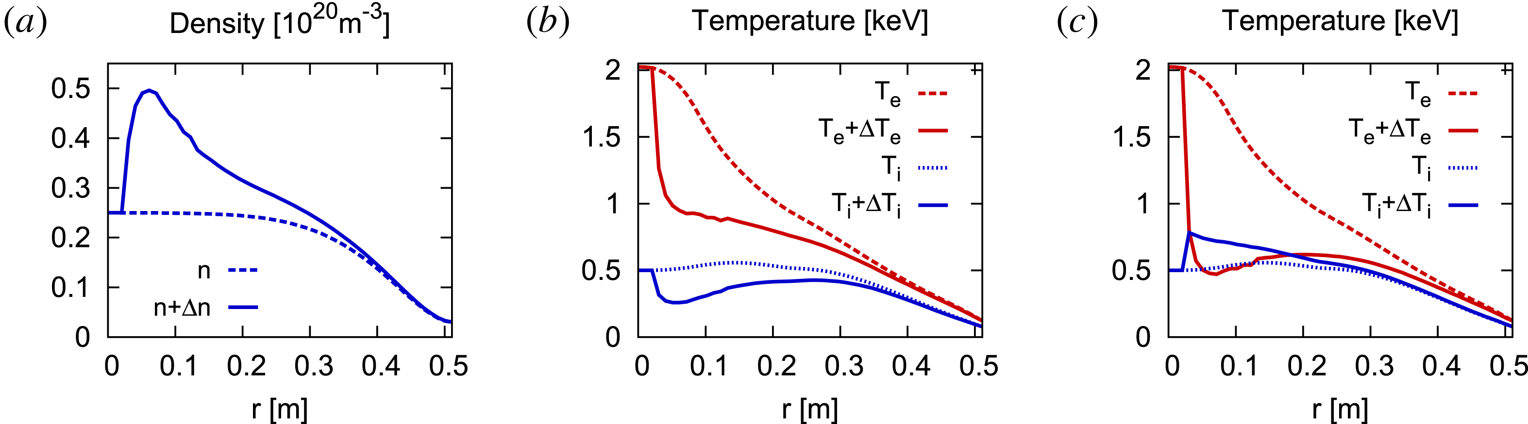
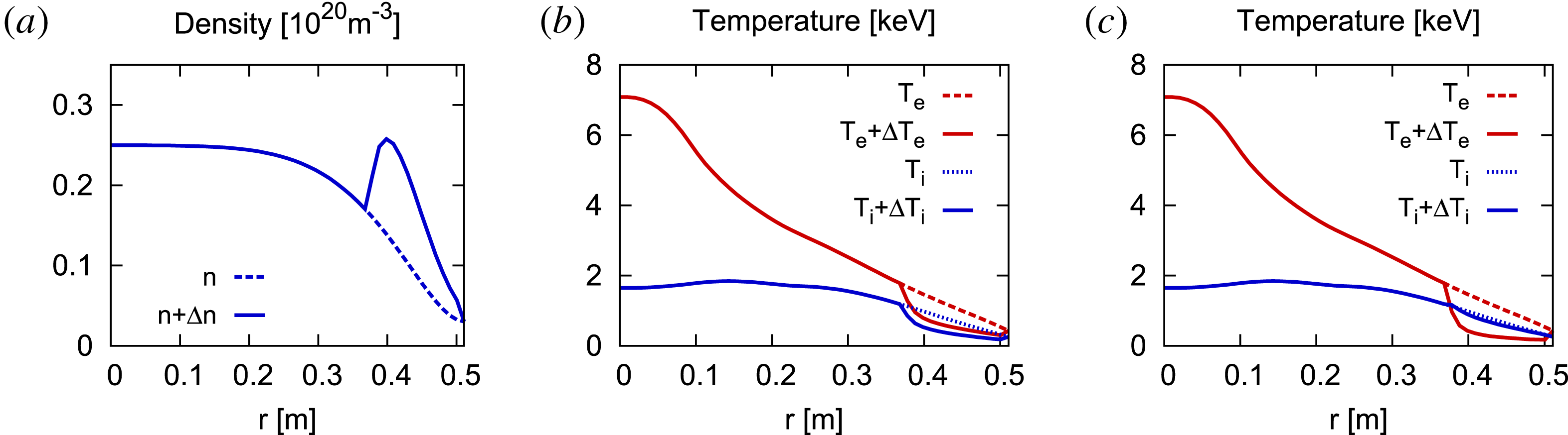
Figures 2 and 3 show calculations of pellet injection into a generic W7-X plasma. Shown are density and temperature profiles before and after pellet injection, with and without accounting for the electron-to-ion energy transfer calculated in the previous section, i.e. setting
 $\unicode[STIX]{x1D6FC}=1$
and
 $\unicode[STIX]{x1D6FC}=0$
, respectively. Figure 2 refers to the very fast
 $(1200~\text{m}~\text{s}^{-1})$
injection planned in the next W7-X experimental campaign, whereas in figure 3 typical steady-state plasma profiles corresponding to the present campaign OP 1.2 were generated with the transport code NTSS (Turkin et al.
Reference Turkin, Beidler, Maaßberg, Murakami, Tribaldos and Wakasa2011) assuming 2 MW central electron cyclotron resonance heating (ECRH). The transport was represented by neoclassical transport coefficients calculated by the DKES code supplemented by an ad hoc turbulent energy diffusion coefficient taken to be inversely proportional to density and equal to
 $0.5~\text{m}^{2}~\text{s}^{-1}$
in the central portion of the plasma. In this way, temperature profiles consistent with typical experimental data were obtained. These profiles are somewhat uncertain because of the scarcity of reliable temperature measurements, and an additional uncertainty stems from the fact that our self-similar solutions are only accurate for pellets small enough not to perturb the background temperature significantly.
Profiles of density (a), ion and electron temperatures for
 $\unicode[STIX]{x1D6FC}=0$
(b), ion and electron temperatures for
 $\unicode[STIX]{x1D6FC}=1$
(c) before and after the injection of
 $10^{20}$
hydrogen atoms in W7-X.

Same as figure 2 for a different pellet deposition profile.

The temperature change has been calculated by integrating (6.7) and (6.8), giving the temperatures
 $$\begin{eqnarray}\displaystyle & \displaystyle T_{e}+\unicode[STIX]{x0394}T_{e}=T_{e}\left(\frac{n}{n+\unicode[STIX]{x0394}n}\right)^{2}, & \displaystyle\end{eqnarray}$$
 $$\begin{eqnarray}\displaystyle & \displaystyle T_{i}+\unicode[STIX]{x0394}T_{i}=-(T_{e}+\unicode[STIX]{x0394}T_{e})+(T_{e}+T_{i})\left(\frac{n}{n+\unicode[STIX]{x0394}n}\right), & \displaystyle\end{eqnarray}$$
after the injection of a large pellet,
 $\unicode[STIX]{x0394}n/n=O(1)$
.
In figure 2–3, the deposition profile was calculated using the ablation rate given by a model of Parks and Turnbull (Parks & Turnbull Reference Parks and Turnbull1978). In the case shown in figure 2 we take a very fast pellet
 $(1200~\text{m}~\text{s}^{-1})$
. A large fraction of the pellet is deposited near the plasma centre, where the ratio of electron-to-ion temperature is the highest. The middle panel in figure 2 shows the result of the modelling without accounting for the fast electron–ion energy transfer (
 $\unicode[STIX]{x1D6FC}=0$
), i.e. the electron and ion pressures are kept constant. Both the ion and the electron temperature drop considerably. The panel on the right in figure 2 takes into account the ambipolar ion heating effect (
 $\unicode[STIX]{x1D6FC}=1$
), and as a result the ion temperature increases.
In the case shown in figure 3 we take present W7-X-relevant pellet parameters (see above). In this scenario the effect of ion heating is less pronounced because the pellet is ablated in the plasma edge, where the electron temperature is barely higher than the ion temperature. Yet, without ambipolar ion heating we would expect a significant ion temperature drop (b), whereas in reality this heating leads to a slight correction of the ion temperature (c).
8 Conclusions
We have presented a simple model of the expansion of a cloud of ablated pellet material along the magnetic field of a tokamak or stellarator. In those limits where the equations can be solved analytically, half of the energy by which the hot background plasma electrons heat the pellet cloud ends up as ion kinetic energy. By the time the pellet cloud has merged with the background plasma, one therefore expects a significant amount of energy transfer from the electron to the ion channel.
It is difficult to predict exactly how much energy gets redistributed in this way. In reality, the pellet evaporates gradually and the ablation cloud drifts across the magnetic field (Parks & Baylor Reference Parks and Baylor2005; Pégourié et al.
Reference Pégourié, Waller, Nehme, Garzotti and Géraud2006) at the same time as it expands along it. In doing so, it emits Alfvén waves and can be subject to instabilities, as is clear from the very fact that as
 $t\rightarrow 0$
, our estimates in § 2 above predict that the pressure of the pellet cloud becomes very large. Our model is thus very simplified, but the basic phenomenon of ion acceleration should still be robust, relying, as it were, only on the basic fact that electrons are lighter than ions and must be held back by an electric field that transfers energy to the ions.
Acknowledgement
We would like to acknowledge several useful discussion with C. Beidler, A. Mishchenko, A. Runov and H. Smith.