INTRODUCTION
Accelerator mass spectrometers with >1 MV tandem particle accelerators are operating around the world since the 1980s. Amongst the most commonly used rare isotopes, we mention 10Be 14C, 26Al, 41Ca, 129I, 236U, and 239/240Pu. By far, the most common isotope used for dating is 14C. Furthermore, 14C is extensively used in biomedical tracing studies. Early high-performance AMS systems were able to achieve 14C background levels in the order of 10−16 by using two magnets in the high-energy spectrometer and charge state 3+. Almost a decade ago, experiments conducted at ETH Zurich demonstrated that 14C AMS could be performed in tandem accelerators with terminal voltages as low as 200 kV by using the charge state 1+ (Synal et al. Reference Synal, Stocker and Suter2007). The system uses only one analyzing magnet in the high energy side of the spectrometer and has a typical background level of 10−15.
Although for sub-MV AMS systems a substantial number of publications and theses (Schulze-König et al. Reference Schulze-König, Seiler, Suter, Wacker and Synal2011; Seiler Reference Seiler2014; Maxeiner at al. Reference Maxeiner, Seiler, Suter and Synal2015), dealt with the details and origins of background reduction, a complete and thorough quantitative understanding of these contributions is still lacking. Consequently, sub-MV systems have not yet achieved background levels in the low 10−16.
At HVE we have experimentally investigated the sources of background in a ~200 kV accelerator system and developed a novel vacuum-insulated accelerator system aiming to deliver background levels in the low 10−16 range.
The Model 4102Bo-AMS Radiocarbon Dating System
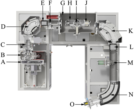
The newly designed 210 kV AMS system is shown in Figure 1 and has a footprint of 3 m × 2.8 m. The carbon ion beam is produced in the hybrid (solid or gas target) SO110-C sputter ion source (Klein at al. Reference Klein and Mous2017). The normalized emittance of the ion source is 2 – 4 mm mrad √MeV up to 250 eµA 12C− (Klein et al. Reference Klein, Gottdang and Mous2013). An XYZ motor driven stage and computer automation are used to auto-tune the ion beam extraction system after source head servicing. The ion beam extraction energy is 40 keV. The low-energy mass spectrometer consists of a 90° H-type dipole magnet with permanent magnets. The magnet gap supports a source divergence as large as 35 mrad for flat-topped transmission. To enable sequential injection of the 3 isotopes by the bouncing technique, the entire H-type magnet, including yoke, is electrically isolated in a high-voltage enclosure. 12C, 13C, and 14C are bounced at a frequency of 100 Hz for sequential transport through the tandem accelerator. The injection periods are 100 µs for the stable isotopes, and the 14C counting efficiency is >90%.
Layout of the 4102Bo-AMS system, showing: A) sample chamber with sample carousel; B) ion source chamber; C) einzel lens; D) bouncer magnet with high voltage enclosure; E) Y-steerer with ion beam blanking capability; F) 12C offset Faraday cup; G) accelerator vessel; H) high-voltage terminal; I) stripper canal; J) magnetic charge state selector; K) high-energy analyzing magnet; L) Y-steerer; M) 12C and 13C offset Faraday cups; N) electrostatic analyzer; and O) 14C gas ionization detector.

The tandem accelerator operates at a nominal terminal voltage of somewhat over 200 kV. It is vacuum insulated, and its in-house developed high-voltage power supply is incorporated in the accelerator vessel. In the stripper canal, helium gas is used for ion beam stripping, resulting in low emittance increase due to small-angle scattering.
Pumping is applied for both sides of the stripper canal by a 600 L/s turbo-molecular pump located at ground potential. It reduces the gas flow towards the low and high-energy acceleration gaps, which in turns reduces unwanted charge-exchange processes that would otherwise lead to increased background levels. The diameters of the stripper canal and the pump restrictions follow the beam envelope as calculated with first order matrix formalism. The exit was further enlarged to accommodate the additional beam phase-space increase caused by scattering in the stripper gas. To minimize the required gas flow, the diameter is the smallest at the beam waist in the center of the stripper canal. A second 600 L/s turbo-molecular pump at the accelerator vessel itself ensures adequate vacuum levels in the acceleration gaps.
A novel feature of the accelerator is a charge state selector located in the accelerator terminal, after the stripper canal. It comprises an all-permanent-magnet based H-type magnet mounted around the stripper exit pump restriction (see J in Figure 1). It has a bending angle of 12°, sufficient to resolve charge state 1+ from charge state 2+.
The high-energy spectrometer includes an all-permanent-magnet 78° analyzing magnet with 400-mm bending radius and a spherical ESA, forming an achromatic ion-optical system. The stable isotopes are measured in offset Faraday cups after the analyzing magnet, while 14C is counted in a single-anode gas ionization detector. One Y-steerer is used to correct small misalignments.
An additional feature of the 14C AMS system is the slit stabilization for the ion beam. It is realized by pairs of electrodes inside the Faraday cups that are mounted with a vertical or horizontal slit between them. Comparing the beam current measured on these electrodes provides information on the beam position. Such slit systems are present in the low-energy 12C offset Faraday cup (for X & Y correction using extraction voltage and LE Y steerer, respectively), in the high-energy 13C Faraday cup (for X correction, using the terminal voltage) and the high-energy 12C Faraday cup (for Y correction, using the HE Y steerer). They ensure stable beam position in the stripper canal and in the 14C detector, respectively. As such, position drifts are avoided, and long-term and stable operation is ensured.
14C Background Limits—an Experimental Investigation
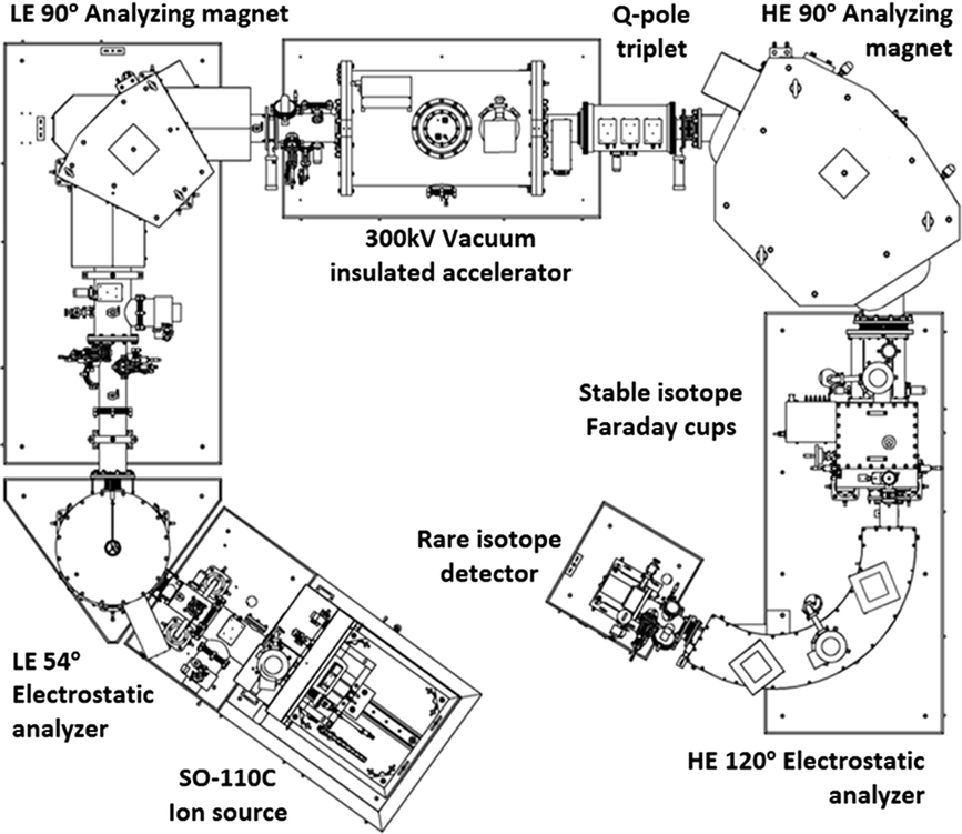
To understand the contributions to the background in the 14C AMS system, we used the compact-version HVE AMS system as described in previous works (Klein at al. Reference Klein, Mous and Gottdang2006) and depicted in Figure 2. The 1 MV Tandetron was substituted by a 300 kV vacuum-insulated tandem accelerator operating at 200 kV terminal voltage. Measurements and considerations indicated that the following contributions play no significant role at 10−16 background levels:
14NH− with 14/15th injection energy of the reference energy.
The molecular breakup of 13CH− by residual gas interaction after the LE analyzing magnet and before acceleration.
Charge exchange processes in the low-energy analyzing magnet or low-energy acceleration gap.
Contributions from 12C originating from 12CH2−. These are rather similar to background contributions originating from 13CH−, albeit being at a lower level.
Memory effects in the ion source (Arnold et al. Reference Arnold, Merchel, Bourlès, Braucher, Benedetti, Finkel, Aumaître, Gottdang and Klein2010).
The layout of the 300 kV vacuum-insulated multi-isotope system.

The measured background level is approximately 10−14. Our experiments identified that the dominant sources of background are related to the injection of molecular 13CH− along with 14C−. Because the natural abundance of 13C is ~10−2 and the molecular contribution by CH− is also ~10−2 (depending to some extent on sample preparation), the injection of 13CH− is typically at the 10−4 level compared to 12C−. In the terminal stripper, 13CH− is dissociated and stripped to 13C1+ with a charge-exchange efficiency of ~45% and to 13C2+ with a charge-exchange efficiency of ~20%.
Three background contributions from 13C1+ were identified referred to as I, II, and III. We assume that the 13CH dissociation in the stripper is complete enough to exclude background contribution.
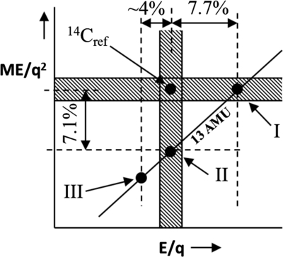
Type I: 13C1+ having the same magnetic rigidity ME/q2 as the 14Cref ion
Type II: 13C1+ having the same electrostatic rigidity E/q as the 14Cref ion
Type III: 13C1+ originating from the primary stripping process
Types I and II relate to the interaction of the 13C beam with the residual gas present in the high-energy acceleration gap. After charge exchange to 2+, a small fraction of these 13C2+ will charge-exchange back to 13C1+, leaving the accelerator with slightly higher energy. Depending on the position of this second charge-exchange process, the additional energy can give the 13C1+ the same magnetic mass-energy product (ME/q2), or the same electrostatic rigidity (E/q) compared to the reference 14C1+.
Type III background originates from the primary stripping process in the stripping canal in the high-voltage terminal. It has lower energy than the 14Cref ion, and a lower magnetic, as well as electrostatic rigidity, compared to the 14Cref ion. It will be suppressed in the high-energy magnet as well as in the high-energy ESA. Figure 3 shows the ambiguity bands for magnetic filters in ME/q2 and electric filters for E/q. Also the type III background is indicated.
Types I, II, and III backgrounds with their magnetic and electrostatic rigidities.

In Table 1, the charge-exchange probability in the high-energy accelerating gap is indicated to be 3×10⁻⁵. It is calculated by assuming a charge-exchange cross-section σ+2,+1 for 200 keV carbon in helium of 3×10⁻¹⁶ cm2 (2), a helium pressure in the high-energy accelerating gap of 2×10⁻⁵ mbar and an interaction length of 2 mm. Measured suppression factors (probabilities) in the high-energy magnet and the high-energy electrostatic analyzer are discussed in the following paragraphs.
This table summarizes the three major contributions to the background of the system, resulting from 13CH− injection. Data shown are relative to 14Cref. The background is calculated from the various contributions to the total suppression (“Total”), assuming 13CH/12C = 10−4 and assuming a 14C+ yield of 45% in the stripping process: Background = Total ×10−4 / 45%.

Background from Magnetic Ambiguity (Contributions I and III)
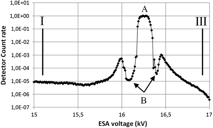
In case 13C1+ has an identical magnetic rigidity as the reference 14C1+, the suppression in the high-energy spectrometer is determined by the electrostatic analyzer (ESA). The difference in electrostatic rigidity is calculated to be +7.7% and –3.9% for type I and type III backgrounds, respectively. To determine the suppression by the ESA, a low-intensity 12C1+ is directed into the entrance of the ESA. The ESA voltage was scanned, and the detector counts were recorded, see Figure 4. The central peak of the scan at 16.26 kV (point A) represents the “14Cref” contribution (normalized to 1). The contributions I and III are found by dividing the reference ESA voltage setting by 1.077 (= 15.10 kV), and 0.961 (= 16.92 kV), respectively. Note that at both sides of the central peak “A,” the local minima indicated by “B” correspond to the beam located in between the entrance of the detector and the end of the ESA electrodes. Summarized in the “HE ESA” column of Table 1 are the suppression factors for the ESA for the backgrounds I and III.
ESA suppression for constant ME/q2 ion beams. Suppression levels of background types I and III are indicated.

Background from Ambiguity in Electrostatic Rigidity (Contributions II and III)
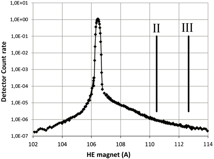
In case 13C1+ has an identical electrostatic rigidity as the reference 14C1+, the high-energy magnet determines the suppression in the high-energy spectrometer. The difference in magnetic rigidity is calculated to be −7.1% and −10.7% for type II and type III backgrounds, respectively.
The suppression by the high-energy analyzing magnet was measured by scanning by the magnet during a low-intensity 12C1+ beam at a constant ESA setting that corresponds to the reference 14C1+ energy. Figure 5 depicts the results.
High-energy analyzing magnet suppression for constant E/q ion beams. Suppression levels of background type II and III are indicated.

The central peak corresponds to the 14C reference path while contributions II and III are at 106.45A/√0.929 = 110.5 A and 106.45A/√0.893 = 112.7 A, respectively. Summarized in Table 1 under column “HE magnet” are the suppression factors of contribution II and III by the high-energy analyzing magnet.
DISCUSSION
It should be noted that the measurements cover a broad dynamic range, of ~7 orders of magnitude. In practice, the scans that are shown in Figures 4 and 5 consists of several “sub-scans” with different intensities of the injected 12C1+. Because of this procedure and the nature of such scans the accuracy of the measured suppressions factors is low, maybe off by a factor 2–3.
Contributions type I and II are related to ions having charge state 2+ after the stripper that change to 1+ within the high-energy acceleration gap. The magnetic charge state selector deflects the potentially interfering 2+ ions before the high energy acceleration. Those ions are stopped before entering the HE magnet or ESA where they could form an ambiguity. This will suppress the background contributions type I and II by at least several orders of magnitude, resulting in background contributions in the low 10−16 regime for this class of background, or even below.
The type III background does not benefit from the magnetic charge state selector in the high-voltage terminal, but it is anticipated to have the lowest background level. To ensure that this class of background does not contribute to the overall background level, the ESA in the newly designed dedicated 14C system has a gap that is sufficiently large to avoid scattering on the inner electrode.
CONCLUSIONS
In this work, we identified and quantified contributions to the background for sub-MV 14C AMS systems. The two dominant contributions are related to 13CH− injected in the stripper yielding 13C2+ → 13C1+ ions and can be suppressed by incorporating a charge state selector after ion beam stripping. We anticipate that this novel vacuum-isolated accelerator system will have background levels in the low 10−16 range, supporting most stringent 14C AMS dating applications. The layout and new feature for high measurement stability of the novel 14C AMS system have been discussed.