1. INTRODUCTION
As future Mars exploration missions become more complex and challenging, Autonomous Navigation (AutoNav) is desirable for a Mars spacecraft to be able to estimate its position independently from Earth stations. The major drawbacks of the traditional Deep-Space Network (DSN)-based navigation approach are the high cost and the low real-time capability (Quadrelli et al., Reference Quadrelli, Wood, Riedel, McHenry, Aung, Cangahuala, Volpe, Beauchamp and Cutts2015). AutoNav can be used to compare with the DSN data for mutual verification or at least as a backup in case of a loss of communication. In the last two decades, several kinds of autonomous navigation approach have been proposed, and autonomous optical navigation is still considered as one of the most feasible solutions for deep-space navigation without requiring the DSN's support (Quadrelli et al., Reference Quadrelli, Wood, Riedel, McHenry, Aung, Cangahuala, Volpe, Beauchamp and Cutts2015; Christian and Lightsey, Reference Christian and Lightsey2010). Therefore, Optical Navigation (OPNAV) has been applied in many deep-space missions, such as the Deep Space 1 (Bhaskaran et al., Reference Bhaskaran, Riedel, Synnott and Wang2000), NEAR Shoemaker (Owen et al., Reference Owen, Wang, Harch, Bell and Peterson2001), Deep Impact (Mastrodemos et al., Reference Mastrodemos, Kubitschek and Synnott2005) and Hayabusa missions (Kubota et al., Reference Kubota, Hashimoto, Kawaguchi, Uo and Shirakawa2006). However, few OPNAV attempts have been made during the approach phase of past Mars missions (Ma et al., Reference Ma, Wang, Jiang, Mu and Baoyin2017).
To support autonomous OPNAV during the Mars approach phase of future Mars exploration missions, image processing and high-precision line-of-sight extraction algorithms should be developed as the core of OPNAV. Li et al. (Reference Li, Lu, Zhang and Peng2013) developed an image processing algorithm for deep-space autonomous OPNAV using a Canny edge detection operator, Least Squares and Levenberg-Marquardt-based ellipse fitting algorithms, but its extraction accuracy is as low as about three pixels even for those images that only contain a normal clear celestial body without starry background noise. Considering oblique moon images without starry background noise, Mortari et al. (Reference Mortari, de Dilectis and Zanetti2015; Reference Mortari, D'Souza and Zanetti2016) developed another image processing algorithm for cislunar OPNAV using mathematical projection and circular and elliptical sigmoid functions in a least-squares algorithm. For interplanetary exploration missions, pixel-level line-of-sight extraction would cause unacceptable positioning error (greater than one million kilometres), therefore some subpixel-level image processing and line-of-sight extraction algorithms would be required to be developed. Considering normal and oblique planet images with starry backgrounds, Du et al. (Reference Du, Wang, Chen, Fang and Su2016) proposed an image processing algorithm using a Prewitt-Zernike moment operator. Its extraction accuracy for the centroid of a planet reached 0·3 pixels, which relied on the selected threshold value. Also, Christian (Reference Christian2017) discussed the performance improvement of the cislunar limb-only OPNAV adopting a Zernike moments-based subpixel edge localisation algorithm. However, a high-precision line-of-sight extraction algorithm that can be used for Mars approach navigation has not yet been published.
Optical image creation is prerequisite for testing and verifying the developed line-of-sight extraction algorithms, especially as there have as yet been no completed missions using this technique. Balster (Reference Balster2005) studied an Earth image simulation system for the Mars Laser Communication Demonstration, which covered geometric projection and illumination reflection but without a starry background. In a similar way, Christian (Reference Christian2010) developed an optical image creation method for Mercury and the Moon without a starry background. On this basis, Lu (Reference Lu2013) further introduced texture features to simulate the terrain, craters and clouds on the surface of Mercury and the Moon. Huang et al. (Reference Huang, Cui and Li2015) presented a semi-physical simulation system of autonomous OPNAV for the Mars approach phase, but the albedo variations of Mars were not considered. Optical image generation procedures suitable for the Mars approach phase are still lacking in recent published literature.
The aim of this paper is to provide an optical image generation procedure and subpixel line-of-sight extraction algorithm for the Mars approach phase and verify their effectiveness. The rest of this paper is organised as follows. Section 2 presents the optical image generation procedure for the Mars approach phase, including geometric projection and nominal line-of-sight, illumination reflection and grey scale calculation and starry background creation. Section 3 introduces the subpixel line-of-sight extraction algorithm for the Mars approach phase, including image segmentation, noise elimination, subpixel real edge extraction, robust ellipse fitting and centroid computation. In Section 4, the composition of the simulation system is described, simulation results are discussed in detail, and the navigation accuracy is also analysed. Finally, Section 5 contains the conclusions.
2. OPTICAL IMAGE GENERATION FOR MARS APPROACH
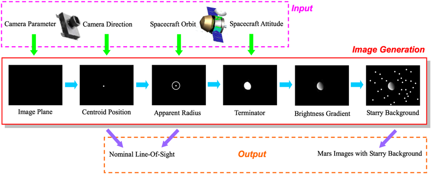
A pre-flight optical image generation system is necessary for a first-time planetary exploration mission. The optical image generation procedure is summarised in Figure 1. The input of the optical image generation module includes camera parameters and direction, spacecraft orbit and attitude. The output of this module contains Mars images with starry backgrounds and nominal line-of-sight information. The optical image generation procedure contains six steps. The image plane, centroid position, apparent radius, terminator, brightness gradient and starry background are determined successively. Note that this image creation procedure does not consider imaging distortion.
Sketch of optical image generation procedure.

2.1. Image plane
The image plane is created according to the number of pixels (length × width) of the given optical camera. We denote L as length and W as the width. In the simulation procedure, the image plane is represented by a matrix with L rows and W columns.
2.2. Nominal centroid position
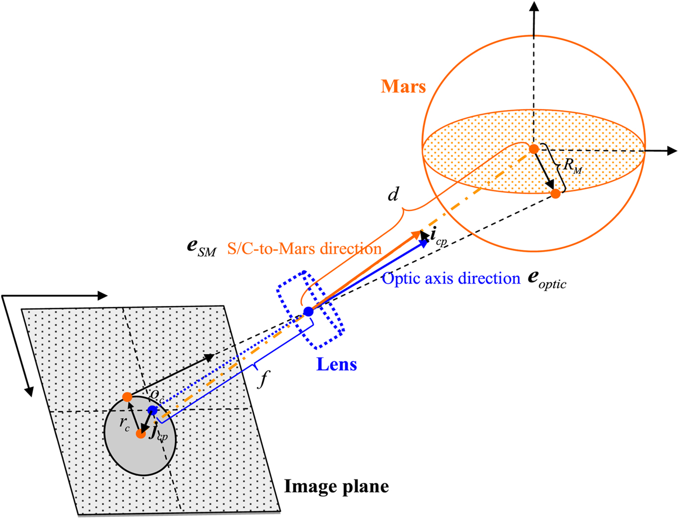
The spacecraft usually flies facing Mars during the approach phase. The optical camera is also assumed to be facing Mars to ensure effective OPNAV and the imaging geometry is assumed to be as a pin-hole camera model (see Figure 2). The position of the Martian centroid at the image plane can be calculated by Equation (4), based on focal length (f) of the camera, spacecraft-to-Mars direction vector eSM and optical axis direction vector eoptic.
Geometrical relationship of pin-hole camera model.

According to geometric similarity in the pin-hole camera model, we have:
 $$\left\{ {\matrix{ {f\cdot {\bi e}_{optic} - f\cdot {\bi e}_{SM} = f\cdot i_{cp}} \cr {\displaystyle{{{\rm \Vert }f\cdot {\bi e}_{optic}{\rm \Vert }} \over {{\rm \Vert }f - {\bi e}_{SM}{\rm \Vert }}} = \displaystyle{{{\rm \Vert }{\bi j}_{cp}{\rm \Vert }} \over {{\rm \Vert }f\cdot {\bi i}_{cp}{\rm \Vert }}}} \cr } } \right.$$
where jcp denotes the Martian centroid position at the image plane, and its direction vector ejcp is subject to:
 $${\bi e}_{jcp} = \displaystyle{{({\bi i}_{cp})_{3 \rightarrow 2}}\over{\Vert ({\bi i}_{cp})_{3 \rightarrow 2}\Vert}}$$
where  $\lpar {\bi i}_{cp}\rpar _{3 \rightarrow 2} = \lsqb i_{cp\_x}\comma \; i_{cp\_y}\rsqb ^{T}$. Thus, the Martian centroid position at the image plane can be obtained by:
 $${\bi j}_{cp} = \Vert {\bi j}_{cp}\Vert \cdot {\bi e}_{jcp}$$
From the matrix view point, the centre coordinate of the image plane is denoted as oc = [L/2, W/2] T. Then, the Martian centroid coordinate at the image plane matrix can be determined by:
 $${\bi p} = {\bi o}_{c} + \hbox{int}({\bi j}_{cp}/p_{e})$$
where p e is the pixel size of the camera, and  $\hbox{int}\lpar \bullet\rpar $ denotes the rounding operator.
For any point at the surface of Mars, its coordinate at the image plane can be determined using a similar form to Equation (4).
2.3. Nominal apparent radius
According to geometric similarity in the pin-hole camera model, the apparent radius r c is calculated as follows (Christian, Reference Christian2010; Lu, Reference Lu2013):
 $$r_{c} = R \cdot {f/d}$$
where d and R respectively denote the spacecraft-to-Mars distance and reference Mars radius. The number of pixels of the apparent radius is calculated by:
 $$R_{c} = \hbox{int}(r_{c}/p_{e})$$
Thus, the maximal diameter on the image plane can also be determined.
2.4. Nominal terminator and illumination area
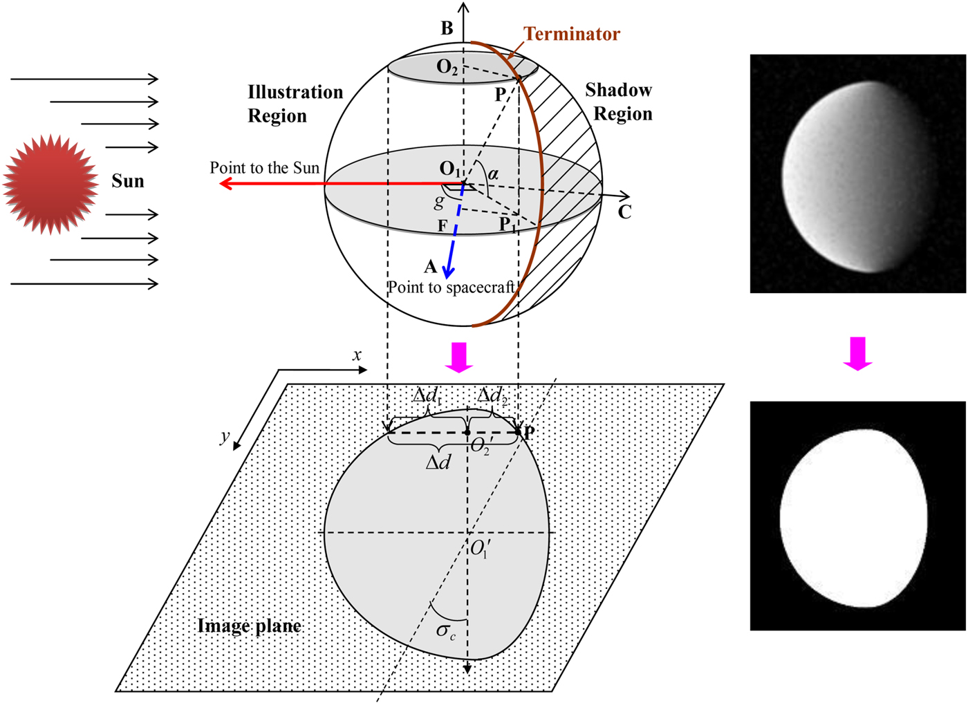
Essentially, the optical camera obtains the Mars image through sensing the reflected illumination from the surface of Mars. Subject to the variable relative geometry relationship of spacecraft-Mars-Sun, the observed phases of the Mars are different. Therefore, here, the calculations of the terminator and then the illumination area are driven by the relative angle between Mars-to-spacecraft and Mars-to-Sun direction vectors.
Sun azimuth g is defined as the angle between the Mars-to-spacecraft and the Mars-to-Sun direction vectors. Here, Mars is seen as a spherical object, and P represents any point on the surface of Mars, thus O 1A = O 1B = O 1C = O 1P = R. According to the geometrical relationship shown in Figure 3, we have:
 $$\left\{ {\matrix{ {FP_1 = O_1P_1\cdot \sin {\rm }\left( {\displaystyle{\pi \over 2} - g} \right)} \hfill \cr {O_1P_1 = O_2P,O_2P^2 = O_1O_2^2 + O_1P^2} \hfill \cr {O_1P_1 = O_1A\cdot \sin \;g = R\cdot {\rm sin}\left( {\displaystyle{\pi \over 2} - g} \right)} \hfill \cr } } \right.$$
Thus, the width of the bright region along the diameter direction can be successively calculated by:
 $$\Delta D = O_{2}P + FP_{1}$$
On the image plane, according to geometric similarity in the pin-hole camera model, we substitute R by r c, and let  $O_{2}^{\prime}\lpar x_{O_{2}}\comma \; y_{O_{2}}\rpar $ slide along the diameter direction, and thus the width of the bright region along the diameter direction can be successively calculated by
 $$\Delta d = \sqrt{O_{1}^{\prime} O_{2}^{\prime 2} + r_{e}^{2}} \left(1 + \sin \left(\displaystyle{{\pi}\over{2}} - g\right)\right)$$
Considering a right nominal imaging, the widths of the bright region on each side of the diameter direction are calculated by:
 $$\left\{ {\matrix{ {\Delta d_1 = \sqrt {O_1^{\prime} O_2^{^{\prime}2} + r_c^2 } } \hfill \cr {\Delta d_2 = \sqrt {O_1^{\prime} O_2^{^{\prime}2} + r_c^2 } \sin \left( {\displaystyle{\pi \over 2} - g} \right)} \hfill \cr } } \right.$$
Then, for any point  $O_{2}^{\prime} \lpar x_{O_{2}}\comma \; y_{O_{2}}\rpar $ at the maximal diameter, there exist two points at the contour of the bright region on each side of the maximal diameter. Their coordinates
 $\lpar x_{P\_1}\comma \; y_{P\_1}\rpar $ and
 $\lpar x_{P\_2}\comma \; y_{P\_2}\rpar $ can be respectively obtained by:
 $$\left\{ {\matrix{ {x_{p\_1} = x_{O_2} - \Delta d_1} \hfill \cr {x_{P\_2} = x_{O_2} - \Delta d_2} \hfill \cr {y_{P\_1} = y_{P\_2} = y_{O_2}} \hfill \cr } } \right.$$
Considering the rotation angle σc of the image (maximal diameter) relative to the image plane, the rotation transformation of any coordinate (x P, y P) on the contour of the bright region is subject to the general form (Balster, Reference Balster2005; Christian, Reference Christian2010):
 $$\left\{ {\matrix{ {x_p^{\prime} = \left( {x_p - O_{c\_x}} \right){\rm }\cos \sigma _c - {\rm }\left( {y_p - O_{c\_y}} \right)\sin \sigma _c + O_{c\_x}} \hfill \cr {y_p^{\prime} = \left( {x_p - O_{c\_x}} \right)\sin \sigma _c + {\rm }\left( {y_p - O_{c\_y}} \right)\cos \sigma _c = O_{c\_y}} \hfill \cr } } \right.$$
where  $\lpar O_{c\_x}\comma \; O_{c\_y}\rpar $ denotes the centre coordinate of the image plane.
Projection geometry from Martian surface to the image plane.

Finally, all coordinates of the edges of the bright region on the image plane can be determined through ergodic calculation. The area between each edge coordinate is filled as the bright region of the Mars image, so that a simulated Mars image without reflected light intensity and brightness gradient is obtained.
2.5. Brightness gradient
In essence, the brightness gradient of the Mars image depends on the albedo variation of Mars itself. From the image view point, the brightness is represented by a grey value, and the brightness gradient is presented as the variation of a grey value. However, the nominal brightness of Mars calculated by Christian's algorithm (Christian, Reference Christian2010) is difficult to directly convert into a series of completely deterministic grey values. Therefore, the maximal nominal grey value G max (brightness) is left for user self-definition (or extraction from an example image). Along the illumination direction, the grey gradient of a Mars image is subject to:
 $$G(i, j) = \left(1 - \displaystyle{{j(i) - j_{\rm start} (i)}\over{j_{\rm end}(i) - j_{\rm start}(i)}}\right) G_{\max}$$
where G(i, j) denotes the grey value at the coordinate (i, j), i is the coordinate along illumination direction and j is the coordinate perpendicular to the illumination direction. j start(i) and j end(i) represent the start and end coordinates in the i-th row of the bright region and j(i) denotes the j-th pixel in the i-th row of the bright region.
In addition, some texture features are also added into the created images to simulate the atmosphere and terrain on the surface of Mars. Lu in our research group created many texture models for simulating planets' images (Li et al., Reference Li, Lu, Zhang and Peng2013; Lu, Reference Lu2013). In this study, those existing texture models are directly used for producing the image of the surface of Mars, and thus they are not detailed here.
2.6. Starry background
In order to simulate the starry background, some stochastic distribution noise points that are subject to Equation (14) are added into the image plane:
 $$\left\{ {\matrix{ {G_{starry}(i_s,j_s) = {\rm int(} \vert 10 - {\rm randn}(1) \vert {\rm )}} \hfill \cr {i_s = {\rm int(}(L - 1)\cdot {\rm rand}(1){\rm )}} \hfill \cr {j_s = {\rm int(}(W - 1)\cdot {\rm rand}(1){\rm )}} \hfill \cr } } \right.$$
where G starry(i s, j s) denotes the grey value at the stochastic coordinate (i s, j s), randn and rand are respectively nominal distribution and uniform distribution functions, and  $\vert \bullet \vert$ represents an absolute value operator. Thus, a simulated optical image of Mars with a starry background is generated.
Note that the amount of background starlight in essence relies on the exposure time length of the camera. In a real Mars mission, the exposure time length of the camera will be calibrated manually or autonomously in orbit. In case of some untimely or inaccurate calibration, we have to intentionally consider the worst situation, that is that a starry background still exists when the spacecraft is close to Mars, to verify the effectiveness of the proposed identification algorithm.
3. LINE-OF-SIGHT EXTRACTION
The function of the line-of-sight extraction module is to identify the centroid coordinates and apparent radius of Mars from the observed image. Since a high-resolution optical camera would output a high dimensional matrix (picture), the latter would create a large computational burden for image processing and identification. The line-of-sight extraction procedure provided here contains three main steps: discover Mars and rough edge images, pseudo-edge elimination and precise edge detection, and robust fitting.
3.1. Objective segmentation and rough edge detection
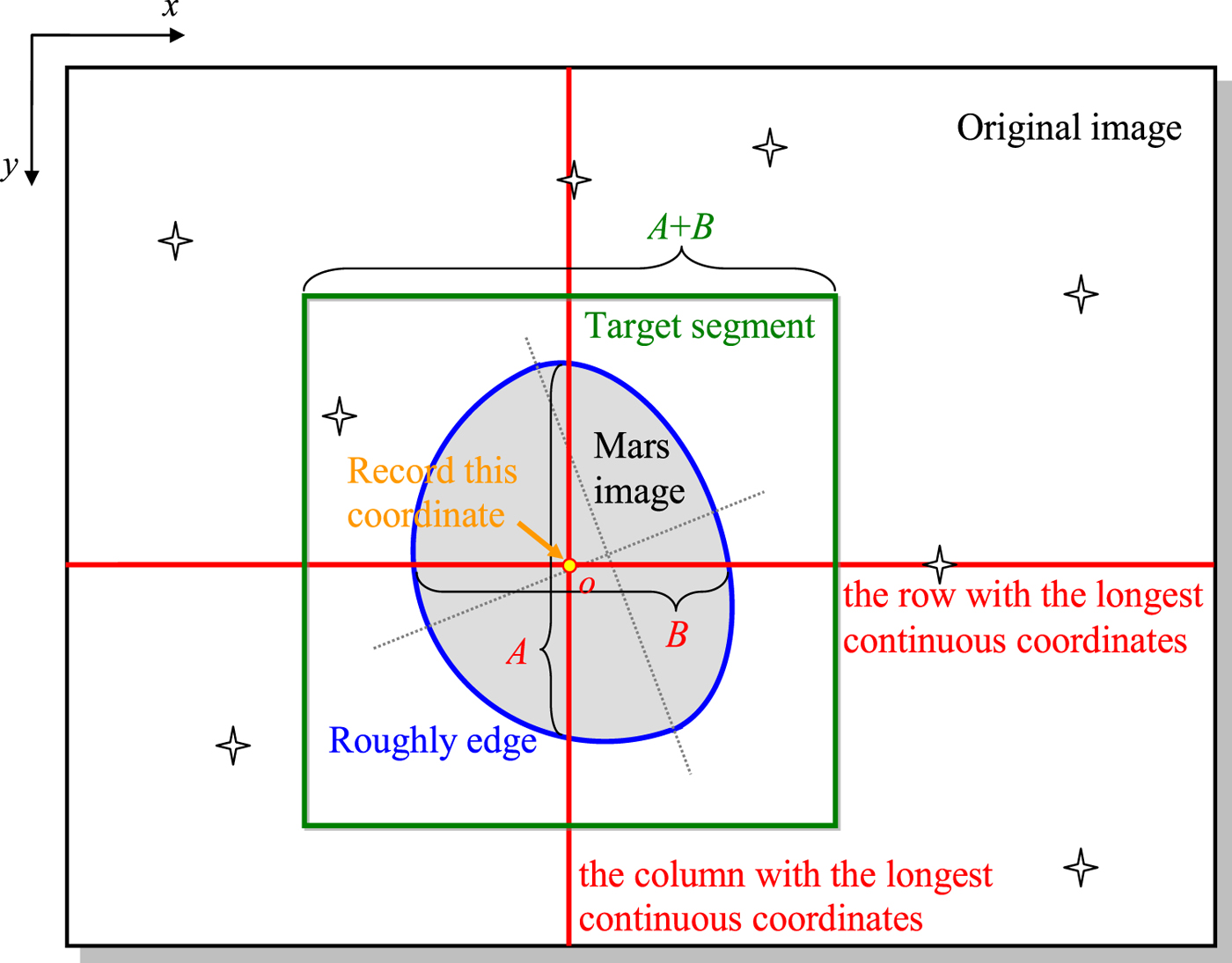
During the approach phase, the spacecraft flies facing Mars, and Mars is the largest target in the field-of-view of the spacecraft. The aim of this step is to segment the largest objective from the original image and roughly detect the edge coordinates of the objective region (see Figure 4).
Step 1: Find a row and a column that have the longest continuous coordinates with their grey value larger than the threshold value τ by reading the row and column of the original image one by one. Meanwhile, the start and end coordinates on each row and column of the longest continuous region are recorded (that is, the rough edge coordinates of the longest continuous region).
Step 2: Calculate the coordinate of the intersection of the found row and column (that is the coordinate of o) and the continuous lengths (pixel number with grey value more than τ) on the found row and column (that is, A and B).
Step 3: Segment the intersection-centred square image block with length of A + B from the original image.
Sketch of Mars identification and segmentation.

In fact, a binarization image would inevitably lose some effective information. To avoid these losses, the Mars image block segmented from the original image is an original local image. As only the neighbourhood domains of the rough edges are used for subsequent precise edge detection, other stars and small bodies in the background would not influence the edge detection.
In many previous studies (Li et al., Reference Li, Lu, Zhang and Peng2013; Mortari et al., Reference Mortari, de Dilectis and Zanetti2015; Reference Mortari, D'Souza and Zanetti2016; Du et al., Reference Du, Wang, Chen, Fang and Su2016; Christian, Reference Christian2017), the planet is usually segmented from the original image through conducting threshold segmentation with a fixed threshold value, and the binarization images are directly used for subsequent edge detection and fitting procedures. However, a suitable fixed threshold value is usually difficult to select in advance to adapt actual images well. Therefore, in this study, the threshold value is automatically selected using the maximisation of interclass variance method (Huang et al., Reference Huang, Yu and Zhu2012).
To distinguish the target and starry background, based on the grey level, the image is divided into two classes W 1 and W 2 at grey value τ, such that:
 $$\left\{ {\matrix{ {W_1 = \{ 0,1,2, \cdots ,\tau \} } \hfill \cr {W_2 = \{ \tau + 1,\tau + 2, \cdots ,\iota - 1\} } \hfill \cr } } \right.$$
where ι is the total number of grey levels of the image. We denote the number of pixels at grey level i to be n i, and the total number of pixels in the given image can be calculated by  $N = \sum\nolimits_{i = 0}^{{\rm \iota } - 1} {n_i} $. Then, the probability of occurrence at grey level i is defined as:
 $$p_i = \displaystyle{{n_i} \over N},{\rm such that }p_i \ge 0,\sum\limits_{i = 0}^{\iota = 1} {p_i} = 1$$
The probabilities of the two classes (W 1 and W 2) are calculated by:
 $$\left\{ {\matrix{ {P_{W1} = \sum\limits_{i = 0}^\tau {p_i} } \hfill \cr {P_{W2} = \sum\limits_{i = \tau + 1}^{\iota - 1} {p_i} } \hfill \cr } } \right.$$
These quantities satisfy P W1 + P W2 = 1. The means of the two classes can be calculated by:
 $$\left\{ {\matrix{ {\mu _{W1} = \sum\limits_{i = 0}^\tau {\displaystyle{{i\cdot p_i} \over {P_{W1}}}} } \hfill \cr {\mu _{W2} = \sum\limits_{i = \tau + 1}^{\iota - 1} {\displaystyle{{i\cdot p_i} \over {P_{W2}}}} } \hfill \cr } } \right.$$
The index function for interclass variance maximisation is formulated as:
 $$\sigma^2 (\tau) = P_{W1} P_{W2} \lpar \mu_{W1} - \mu_{W1}\rpar ^{2}$$
The optimal threshold τ* can be obtained by maximising the interclass variance:
 $$\tau^{\ast} = \hbox{arg}\ \mathop{\hbox{max}}\limits_{0 < \tau < l - 1} \sigma^{2}(\tau)$$
Thus, pixel-level edges (real and pseudo-edges) can be obtained.
3.2. Pseudo-edge elimination and precise edge detection
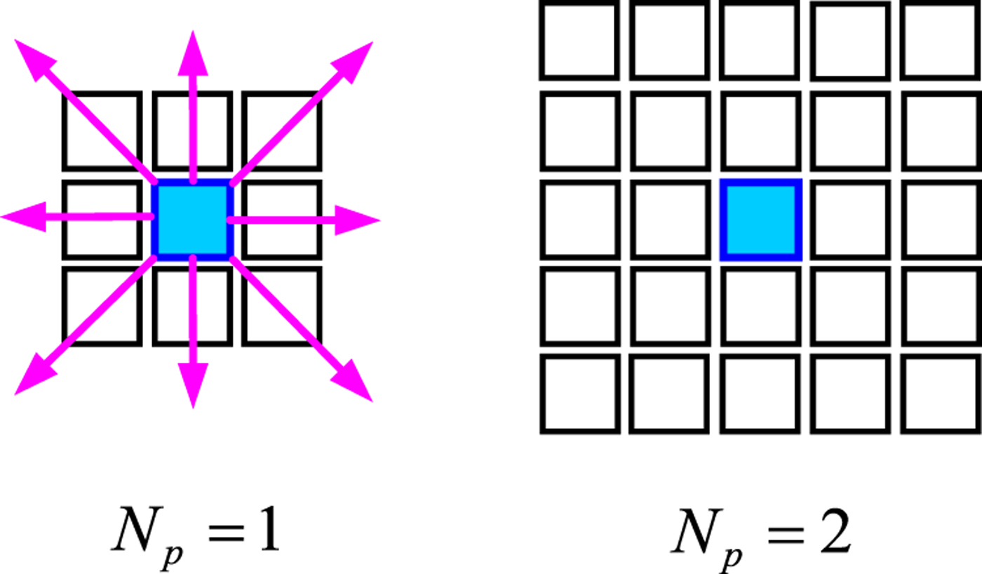
In order to provide more accurate source data for line-of-sight extraction, precise edge detection is conducted in the neighbourhood around the pixel-level edge obtained in Section 3.1. The size of the Mars image changes with the distance of the spacecraft to Mars, but some previous studies have considered a size-fixed neighbourhood for precise edge detection (Du et al., Reference Du, Wang, Chen, Fang and Su2016; Christian, Reference Christian2010). This would generate too much data for edge detection of a small objective and insufficient data for precise edge detection of a large objective. To improve efficiency, a size-variable neighbourhood is considered here. The size of the neighbourhood is defined by:
 $$N_{p} = \hbox{int}\left(\hbox{lg} \displaystyle{{A + B}\over{2}}\right)$$
where N p represents the pixel number of the size of the neighbourhood (see Figure 5).
Sketch of size-variable neighbourhood domain for precise edge detection.

Here, precise edge detection employs local operators to calculate the first derivative of grey level gradient in the neighbourhood domain of each pixel-level edge. The partial derivatives in the horizontal direction F h(x, y) and vertical direction F v(x, y) are defined as:
 $$F_{h}(x, y) = \sum_{i = -N_{p}}^{N_{p}} f\lpar x + N_{p}, y + i\rpar - \sum_{i = -N_{p}}^{N_{p}} f\lpar x - N_{p}, y + i\rpar $$
 $$F_{v}(x, y) = \sum_{i = -N_{p}}^{N_p} f\lpar x + i, y + N_{p}\rpar - \sum_{i = -N_{p}}^{N_{p}} f\lpar x + i, y - N_{p}\rpar $$
where f(x, y) denotes the grey value of point (x, y). Thus, the gradient magnitude F(x, y) of any (x, y) point on the edge is calculated by:
 $$F(x, y) = \sqrt{F_{h}^{2} (x, y) + F_{v}^{2} (x, y)}$$
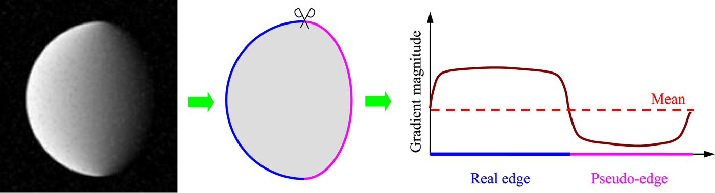
Unlike the previous studies (Mortari et al., Reference Mortari, D'Souza and Zanetti2016; Du et al., Reference Du, Wang, Chen, Fang and Su2016; Christian, Reference Christian2017), here, the gradient magnitude is used for pseudo-edge removal. Pseudo-edges usually occur at the border between a sunlit face and backlit face. It can be found that the gradient magnitudes of the edge points near the backlit face are usually smaller than those on the sunlit face, if mapping the edge into a two-dimensional space (see Figure 6).
Sketch of two-dimensional space mapping of real and pseudo-edges.

Hence, the mean of gradient magnitudes of pixel-level edge points is used as the threshold value to eliminate pseudo-edges. If it is satisfied that:
 $$F(x^{\prime}, y^{\prime}) \geq \displaystyle{{\sum F(x, y)}\over{N_{redge}}}$$
the point (x′, y′) means a real edge point. N redge denotes the total number of the pixel-level edge points.
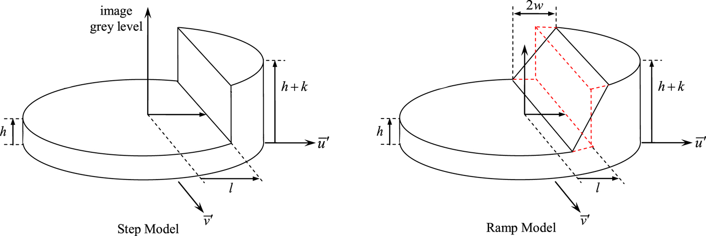
The traditional Zernike moment-based sub-pixel edge detection technique is based on a step model (Du et al., Reference Du, Wang, Chen, Fang and Su2016; Christian, Reference Christian2017). However, the step function model would introduce a bias in the edge location when the edge in the actual image changes gradually (Lyvers et al., Reference Lyvers, Mitchell, Akey and Reeves1989). Mars has an atmosphere layer, and the grey-level of its edge in actual image changes gradually. Therefore, a ramp model is introduced to modify the traditional Zernike moment-based sub-pixel edge detection algorithm. The presented design proceeds with the use of Zernike moments for two reasons. Firstly, the Zernike moment-based technique makes use of integral operators which are easier to analytically evaluate and secondly, fewer moments are needed to obtain the edge location estimate, thus improving computation efficiency.
First, as shown in Figure 7, a unit circle coordination system is defined. The moment-based edge detection techniques need to calculate a handful of low-order moments defined within a unit circle and then use the relative values of these moments to infer the orientation and location of the edge. We denote a set of the pixel-level edge points located at integer pixel locations  $\lcub \tilde{u}_{i}\comma \; \tilde{v}_{i}\rcub \semicolon \; i = 1\comma \; \cdots\comma \; N_{redge}$ and centre a N × N mask about the pixel coordinate
 $\lcub \tilde{u}_{i}\comma \; \tilde{v}_{i}\rcub $ and inscribe a circle within this mask. In this paper, N is set as five. Then, a new coordinate system whose origin is at
 $\lcub \tilde{u}_{i}\comma \; \tilde{v}_{i}\rcub $ with length scaled by 2/N is defined as:
 $$\left\{ {\matrix{ {\bar u = \displaystyle{2 \over N}(u - {\tilde u}_i)} \hfill \cr {\bar v = \displaystyle{2 \over N}(v - {\tilde v}_i)} \hfill \cr } } \right.$$
Thus, the ramp model is defined as:
 $$I(\bar u^{\prime}) = \left\{ {\matrix{ {h,} \hfill & {{\bar u}^{\prime} \le l - w} \hfill \cr {h + k[{\bar u}^{\prime} - (l - w)]/(2w),} \hfill & {l - w < {\bar u}^{\prime} < l + w} \hfill \cr {h + k,} \hfill & {{\bar u}^{\prime} \ge l + w} \hfill \cr } } \right.$$
where  $\bar{u}^{\prime}$ denotes the position along an axis perpendicular to the edge, w represents half of the full edge width and l is the edge location. This ramp function is used to replace the step function as the edge model that is defined within the unit circle.
Sketch of two-dimensional sub-pixel edge models.

The Zernike moment of order n and repetition m for the two-dimensional image  $f\lpar \bar{u}\comma \; \bar{v}\rpar $ is defined within the unit circle as:
 $$Z_{nm} = \displaystyle{{n + 1} \over \pi }\int\!\!\!\int\limits_{{\bar v}^1 + {\bar v}^2 \le 1} {f(\bar u,\bar v)T_{nm}(r,\theta )d\bar ud\bar v} $$
where T nm(r, θ) is the Zernike moment kernel function defined in the polar coordinates that satisfies:
 $$\left\{ {\matrix{ {r^2 = {\bar u}^2 + {\bar v}^2} \hfill \cr {\tan \theta = \bar v/\bar u} \hfill \cr } } \right.$$
 $$T_{nm} (r, \theta) = R_{nm} (r) \exp (jm \theta)$$
where  $j = \sqrt{-1}$. The orthogonal polynomial R nm(r) is defined as:
 $$R_{nm} = \sum\limits_{s = 0}^{(n - \vert m \vert )/2} {\displaystyle{{{( - 1)}^s(n - s)!r^{n - 2s}} \over {s!\left( {\displaystyle{{n + \vert m \vert } \over 2} - s} \right)!\left( {\displaystyle{{n - \vert m \vert } \over 2} - s} \right)!}}} $$
It is common practice to define the integral term in Equation (28) as:
 $$A_{nm} = \int\!\!\!\int\limits_{{\bar u}^2 + {\bar v}^2 \le 1} {f(\bar u,\bar v)T_{nm}(\bar u,\bar v)d\bar ud\bar v} $$
such that Z nm can be rewritten as:
 $$Z_{nm} = \displaystyle{{n + 1}\over{\pi}} A_{nm}$$
If the image is rotated by an angle ψ counter-clockwise, the Zernike moments of the rotated image would be:
 $${A_{nm}}^{\prime} = A_{nm} \exp (-jm\psi)$$
where  ${A_{nm}}^{\prime}$ is the Zernike moment aligned with the edge in the
 $\bar{u}^{\prime} - \bar{v}^{\prime}$ coordinate system, and A nm is the Zernike moment of the original image in the
 $\bar{u} - \bar{v}$ coordinate system.
Considering the component of  ${A_{11}}^{\prime}$, and recalling that exp( − jmψ) = cos(mψ) − jsin(mψ) to find:
 $$\psi = \hbox{arc}\ \tan (\hbox{Im}[A_{11}], \hbox{Re}[A_{11}])$$
Thus, the orientation of the edge could be found only using one Zernike moment A 11.
For an edge model as a step function, the distance (l s) of the edge from the centre of the unit circle can be calculated as follows:
 $$l_{s} = \displaystyle{{A_{20}}\over{{A_{11}}^{\prime}}}$$
Then,  ${A_{11}}^{\prime}$ and A 20 can be analytically solved.
 $${A_{11}}^{\prime} = \displaystyle{{2k(1 - l_{s}^{2})^{3/2}}\over{3}}$$
 $$A_{20} = {A_{20}}^{\prime} = \displaystyle{{2kl_{s}(1 - l_{s}^{2})^{3/2}}\over{3}}$$
However, Equation (36) cannot produce a good estimate of the edge location for gradually changing Martian edges. Hence, the step function edge model is replaced by the ramp edge model from Equation (27). The ramp edge model also permits the integrals for the moments  ${A_{11}}^{\prime}$ and A 20 to be solved analytically:
 $$\eqalign{ A_{11}^{\prime} =& \displaystyle{k \over {24w}}{\rm \{ }3\sin ^{ - 1}(l + w) - 3\sin ^{ - 1}(l - w) - [5(l - w) - 2(l - w)^3][1 - (l - w)^2]^{1/2} \cr & + [5(l + w) - 2(l + w)^3][1 - (l + w)^2]^{1/2}{\rm \} }} $$
 $$\matrix{ {A_{20}} \hfill & { = A_{20}^{\prime} = \displaystyle{k \over {15w}}{\rm \{ }{[1 - {(l - w)}^2]}^{5/2} - {[1 - {(l + w)}^2]}^{5/2}{\rm \} }} \hfill \cr } $$
As expected, the moments calculated from Equations (39) and (40) approach the results of the step model (Equations (37) and (38)) as w → 0. Then, we have:
 $$\displaystyle{{A_{20}}\over{{A_{11}}^{\prime}}} \approx l[1 - (1 + l/2)w^{2}]$$
Thus, the edge location l for the ramp model can be analytically solved, and its result is:
 $$l = \displaystyle{{1 - w^{2} - \lsqb (w^{2} - 1)^{2} - 2w^{2} A_{20}/{A_{11}}^{\prime}\rsqb ^{1/2}}\over{w^{2}}}$$
The result for ψ from Equation (35) allows for straightforward calculation of the normal direction of the edge in the image plane:
 $${\bi n} = \left[ {\matrix{ {n_u} \cr {n_v} \cr } } \right] = \left[ {\matrix{ {\cos \psi } \cr {\sin \psi } \cr } } \right]$$
Then, the edge location in the normalised coordinate system can be calculated by:
 $$\left[ {\matrix{ {\bar u} \cr {\bar v} \cr } } \right] = l\left[ {\matrix{ {\cos \psi } \cr {\sin \psi } \cr } } \right]$$
Finally, according to Equation (26), the sub-pixel coordinate of the edge in the original image is:
 $$\left[ {\matrix{ {u_i} \cr {v_i} \cr } } \right] = \left[ {\matrix{ {{\tilde u}_i} \cr {{\tilde v}_i} \cr } } \right] + \displaystyle{{Nl} \over 2}\left[ {\matrix{ {\cos \psi } \cr {\sin \psi } \cr } } \right]$$
where (u i, v i) is the sub-pixel coordinate of the edge.
3.3. Robust ellipse fitting
Once candidate sub-pixel edges are obtained, line-of-sight extraction can be done through an ellipse fitting. Ellipse fitting is designed to obtain the centroid and the apparent radius of Mars, but noise and incorrect source points potentially exist that may mislead some traditional fitting algorithms. To enhance the robustness against the potential noise and incorrect source data, the direct least-square fitting algorithm (Fitzgibbon et al., Reference Fitzgibbon, Pilu and Fisher1999; Li et al., Reference Li, Lu, Zhang and Peng2013; Du et al., Reference Du, Wang, Chen, Fang and Su2016; Christian, Reference Christian2017) has been improved.
Considering the general form of an ellipse equation:
 $$F_{e}({\bi a}, {\bi x}_{i}) = {\bi a} \cdot {\bi x}_{i} = ax_{i}^{2} + bx_{i}y_{i} + cy_{i}^{2} + dx_{i} + ey_{i} + f_{e} = 0$$
where (x i, y i) is a point on the ellipse,  ${\bi x}_{i} = \lsqb x_{i}^{2}\comma \; x_{i} y_{i}\comma \; y_{i}^{2}\comma \; x_{i}\comma \; y_{i}\comma \; 1\rsqb ^{T}$, a = [a, b, c, d, e, f e] T, and the coefficients of the equation satisfy:
 $$b^{2} - 4ac < 0$$
However, the imposition of this inequality constraint makes it difficult to guarantee a solution of this constrained problem. The form allows the constant to be scaled arbitrarily such that the ellipse inequality constraint may be rewritten as an equality constraint as:
 $$4ac - b^{2} = 1$$
This constraint can be rewritten in a matrix form:
 $$4ac - b^2 = {\bi a}^T\left[ {\matrix{ 0 & 0 & 2 & 0 & 0 & 0 \cr 0 & { - 1} & 0 & 0 & 0 & 0 \cr 2 & 0 & 0 & 0 & 0 & 0 \cr 0 & 0 & 0 & 0 & 0 & 0 \cr 0 & 0 & 0 & 0 & 0 & 0 \cr 0 & 0 & 0 & 0 & 0 & 0 \cr } } \right]{\bi a} = {\bi a}^T{\bi Ca} = 1$$
The objective function of the constrained ellipse fitting problem for classic direct least-square fitting is (Fitzgibbon et al., Reference Fitzgibbon, Pilu and Fisher1999):
 $$\min J_{0} = \Vert {\bi D} \cdot {\bi a}\Vert^{2}$$
where the design matrix D = [x1, x2, · · · , xn] T.
However, once a point detected by the edge detection algorithm mentioned in the previous section dose not lie exactly on the ellipse, it would cause F e(a, xi) ≠ 0. In order to enhance robustness, we introduce a Lagrange multiplier λ to reconstruct a joint objective function as:
 $$\min J = \Vert {\bi D} \cdot {\bi a}\Vert ^{2} + \lambda \lpar 1 - {\bi a}^{T}{\bi Ca}\rpar $$
Then, the fitting problem can be treated as a rank-deficient generalised eigenvalue problem:
 $$2{\bi D}^{T} {\bi Da} - 2\lambda {\bi Ca} = {\bf 0}$$
Substituting Equation (52) into the objective function Equation (51), there is:
 $$J = {\bi a}^{T} {\bi D}^{T} {\bi Da} + \lambda \lpar 1 - {\bi a}^{T} {\bi Ca}\rpar = {\bi a}^{T} \lambda {\bi Ca} + \lambda - \lambda {\bi a}^{T} {\bi Ca} = \lambda$$
Unfortunately, if the candidate edge lies exactly on or very close to the ellipse, DTD would become singular and no solution can be obtained (Christian and Lightsey, Reference Christian and Lightsey2012). To avoid this issue, the fitting approach is further modified below. Redefine a, C and D as follows:
 $${\bi a} = \lsqb {\bi a}_1, {\bi a}_2\rsqb ^{T}, \quad {\bi a}_{1} = \lsqb a, b, c\rsqb ^{T}, \quad {\bi a}_{2} = \lsqb d, e, f_{e}\rsqb ^{T}$$
 $${\bi C} = \left[ {\matrix{ {{\bi C}_1} & {{\bf 0}_{3 \times 3}} \cr {{\bf 0}_{3 \times 3}} & {{\bf 0}_{3 \times 3}} \cr } } \right],\quad {\bi C}_1 = \left[ {\matrix{ 0 & 0 & 2 \cr 0 & { - 1} & 0 \cr 2 & 0 & 0 \cr } } \right]$$
 $${\bi D} = {\rm [}{\bi D}_1,{\bi D}_2],\quad {\bi D}_1 = \left[ {\matrix{ {x_1^2 } & {x_1y_1} & {y_1^2 } \cr {x_2^2 } & {x_2y_2} & {y_2^2 } \cr \vdots & \vdots & \vdots \cr {x_n^2 } & {x_ny_n} & {y_n^2 } \cr } } \right],\quad {\bi D}_2 = \left[ {\matrix{ {x_1} & {y_1} & 1 \cr {x_2} & {y_2} & 1 \cr {t \vdots } & \vdots & \vdots \cr {x_n} & {y_n} & 1 \cr } } \right]$$
Define the scatter matrix as:
 $${\bi S} = {\bi D}^T{\bi D} = \left[ {\matrix{ {{\bi S}_1} & {{\bi S}_2} \cr {{\bi S}_2^T } & {{\bi S}_3} \cr } } \right],\quad {\bi S}_1 = {\bi D}_1^T {\bi D}_1,\quad {\bi S}_2 = {\bi D}_1^T {\bi D}_2,\quad {\bi S}_3 = {\bi D}_2^T {\bi D}_2$$
Substituting Equations (54) – (57) into Equation (52), there is:
 $${\bi S}_{1}{\bi a}_{1} + {\bi S}_{2}{\bi a}_{2} = \lambda {\bi C}_{1}{\bi a}_{1}$$
 $${\bi S}_{2}^{T}{\bi a}_{1} + {\bi S}_{3}{\bi a}_{2} = {\bf 0}_{3 \times 1}$$
 $${\bi a}_{2} = -{\bi S}_{3}^{-1} {\bi S}_{2}^{T} {\bi a}_{1}$$
We note that S3 is only singular when all the points lie on a line. So S3 is invertible in the ellipse fitting process. Finally, we insert Equation (60) into Equation (58), then the solution for a1 can be obtained from the eigenvalue problem:
 $${\bi C}_{1}^{-1} \lpar {\bi S}_{1} - {\bi S}_{2}{\bi S}_{3}^{-1}{\bi S}_{2}^{T}\rpar {\bi a}_{1} = \lambda {\bi a}_{1}$$
There generally exist three possible solutions for this eigenvalue problem. Fortunately, there is always only one eigenvector of  ${\bi C}_{1}^{-1} \lpar {\bi S}_{1} - {\bi S}_{2} {\bi S}_{3}^{-1} {\bi S}_{2}^{T}\rpar $ that meets the constraint Equation (47), which is the solution for a1, and the solution for a2 will be obtained through substituting the result for a1 into Equation (60).
After that, the centroid of Mars can be typically calculated by the standard ellipse parameters that are given as follows:
 $$x_{c} = \displaystyle{{2cd - be}\over{b^{2}} - 4ac}, \quad y_{c} = \displaystyle{{2ae - bd}\over{b^{2}} - 4ac}$$
 $$A_{e} = \sqrt{\displaystyle{{2\lsqb ae^{2} + cd^{2} - bde + f_{e}(b^{2} - 4ac)\rsqb }\over{(b^{2}- 4ac) \left[\sqrt{(a - c)^{2} + b^{2}} - a - c\right]}}}$$
 $$B_{e} = \sqrt{\displaystyle{{2\lsqb ae^{2} + cd^{2} - bde + f_{e} (b^{2}- 4ac)\rsqb }\over{(b^{2} - 4ac) \left[-\sqrt{(a - c)^{2} + b^{2}} - a - c\right]}}}$$
 $$\phi = \left\{ {\matrix{ {0,} \hfill & {b = 0\,{\rm and }\,a < c} \hfill \cr {\displaystyle{\pi \over 2},} \hfill & {b = 0\,{\rm and }\,a > c} \hfill \cr {\displaystyle{1 \over 2}{\cot }^{ - 1}\left( {\displaystyle{{a - c} \over b}} \right),} \hfill & {b \ne {\mkern 1mu} 0\,{\rm and }\,a < c} \hfill \cr {\displaystyle{\pi \over 2} + \displaystyle{1 \over 2}{\cot }^{ - 1}\left( {\displaystyle{{a - c} \over b}} \right),} \hfill & {b \ne {\mkern 1mu} 0\,{\rm and }\,a > c} \hfill \cr } } \right.$$
where (x c, y c) is the centre coordinate, A e and B e denote the semi-major and semi-minor axes of the ellipse, and ϕ represents the angle from the x-axis to the major ellipse axis. With these parameters obtained by Equations (62) – (65), in the camera coordinate system, the line-of-sight direction vector from the spacecraft to the centroid of Mars can be easily calculated by (Du et al., Reference Du, Wang, Chen, Fang and Su2016; Lu, Reference Lu2013; Christian, Reference Christian2010):
 $${\bi e}_c = \displaystyle{1 \over {\sqrt {x_c^2 + y_c^2 + f^2} }}\left[ {\matrix{ { - x_c} \cr { - y_c} \cr f \cr } } \right]$$
4. SIMULATION EXPERIMENTS AND DISCUSSIONS
Simulation experiments were performed to test the effectiveness of image creation and validate the detection accuracy for the line-of-sight extraction algorithm.
4.1. Framework of optical image simulation system
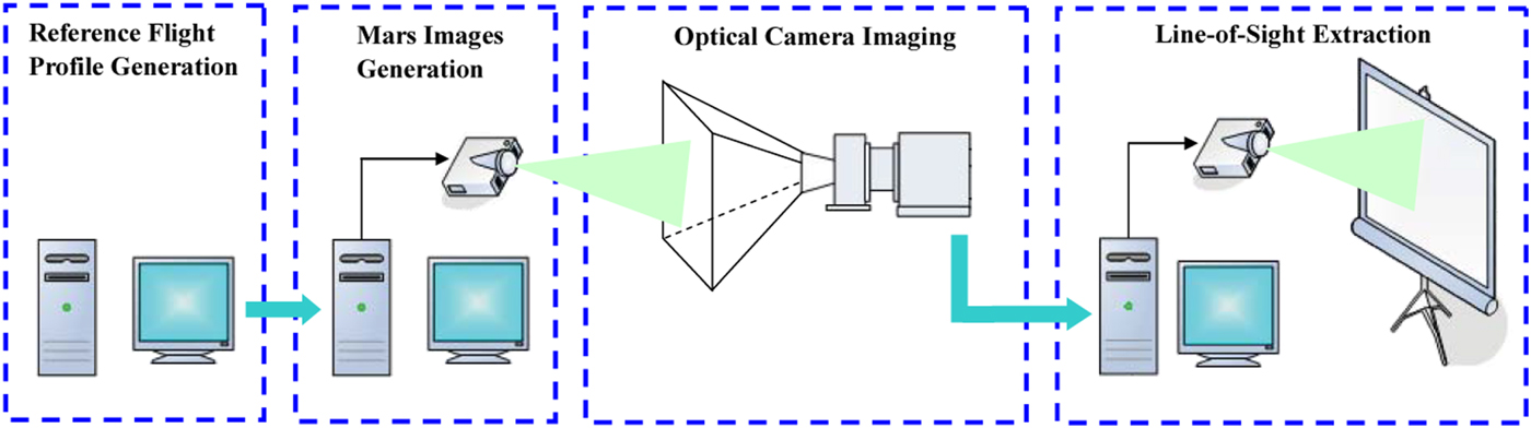
The optical image simulation system is established as shown in Figure 8. It covers reference flight profile generation of Mars spacecraft, Mars images generation, optical imaging and line-of-sight extraction.
Framework of optical image simulation system.

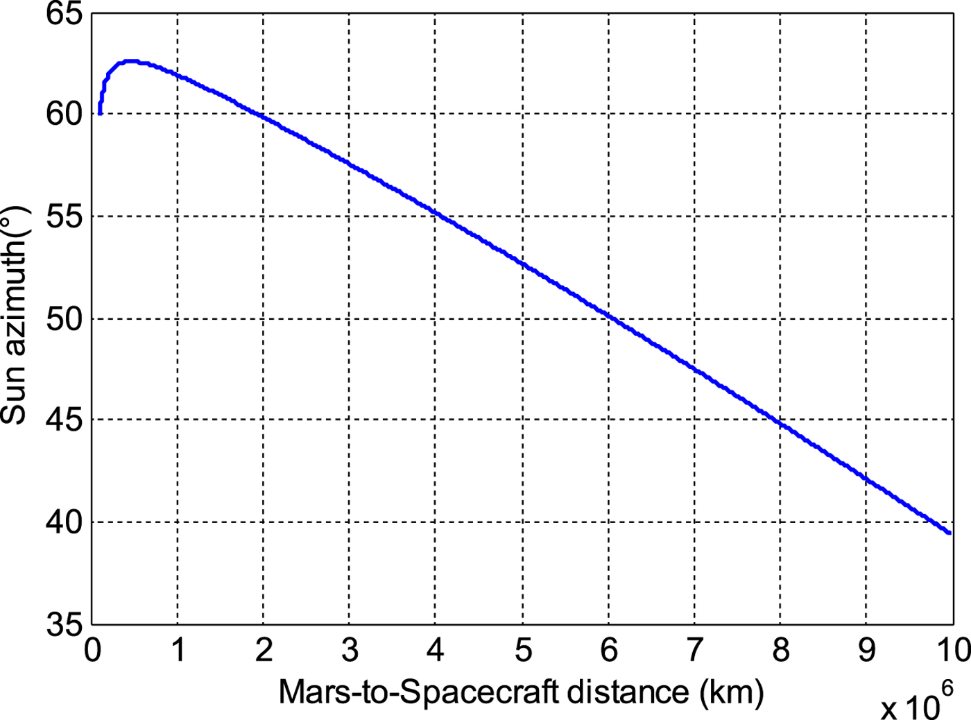
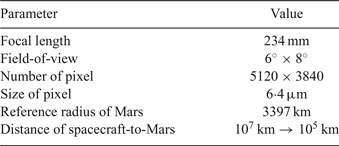
The reference flight profile generation module is to provide orbit and attitude information of the Mars spacecraft. Here, we directly use Satellite Tool Kit (STK®) and MATLAB® to generate an optimal reference profile for Mars spacecraft during the approach phase; see Figure 9. This is according to the mission design parameters and approach illustrated by Jiang et al. (Reference Jiang, Yang and Li2018). The results are utilised to drive the subsequent simulation process. The Mars image generation module is to provide Mars images in the field-of-view of the optical camera of the Mars spacecraft. The optical camera imaging module adopts a candidate optical camera for a Mars mission to sense the simulated Mars images, and the simulated images are exactly sensed by the camera. The line-of-sight extraction module is to implement image processing and sub-pixel level line-of-sight extraction, and then display the identification results. In addition, simulation parameters are set as shown in Table 1.
Reference flight profile generated by STK and MATLAB.

Simulation parameters.

4.2. Results of optical image generation
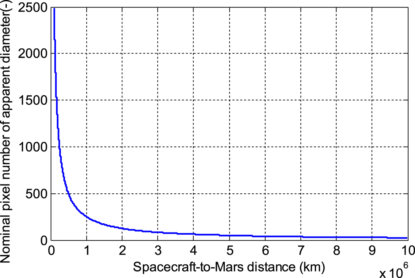
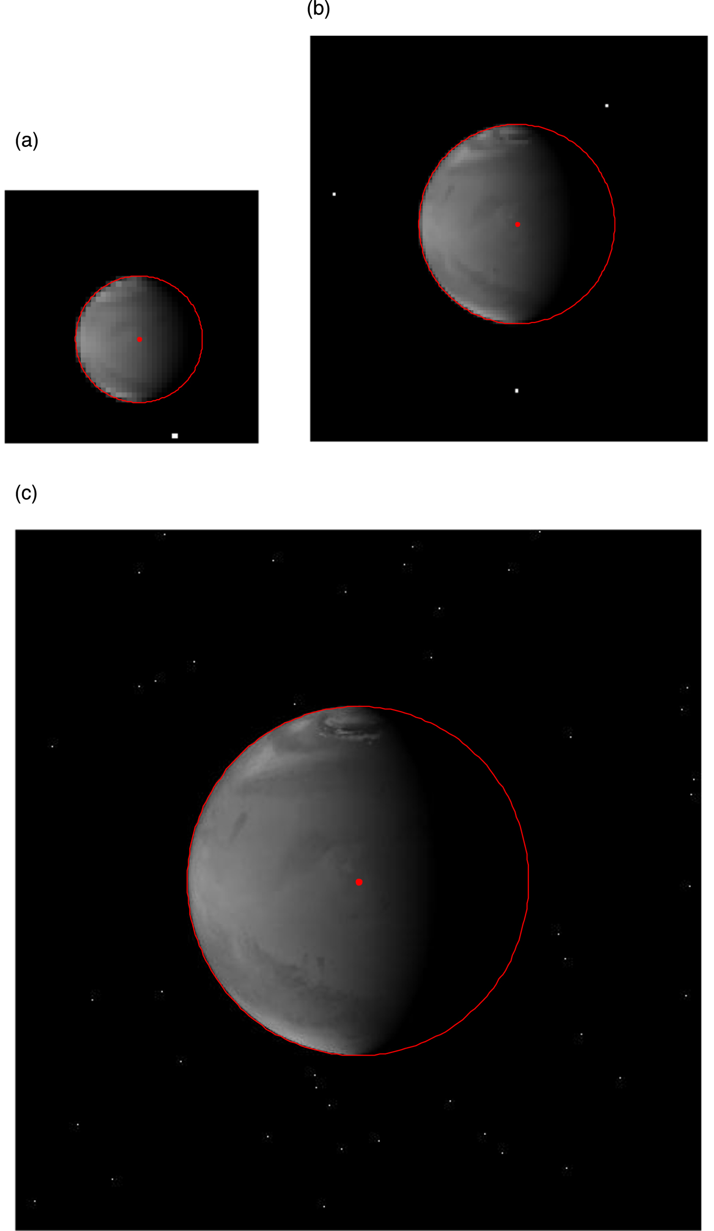
The optical image creation procedure is driven by the reference flight profile and Mars images sensed from the spacecraft-to-Mars distance of 107 km to 105 km are generated. The size of the generated images is 5, 120 × 3, 840 pixels. The simulated images are sequence images that change with the flight state of the spacecraft. As shown in Figure 10, the pixel number of apparent diameter of Mars on the image plane changes from about 25 pixels (at 107 km) to approximately 2,500 pixels (at 105 km). From the spacecraft-to-Mars distance of 107 km to 106 km and from 106 km to 105 km, the size of Mars on the image plane is respectively enlarged about ten times. Therefore, in this section, several representative images are selected to show here, including the images at the spacecraft-to-Mars distances of 107 km, 106 km and 105 km, respectively.
Nominal pixel number of apparent diameter.

Simulated Mars images with various surface textures and solar azimuth angles are shown in Figures 11 – 13. These three figures respectively show the images at distances of 107 km, 106 km, and 105 km from Mars where their solar azimuth angles at these distances are as shown in Figure 9. It can be found that these simulated images contain a starry background and an expected-size Mars image with atmosphere and terrain textures. As expected, the effect of changed illumination phase angle is also exactly presented in all simulated images. The sunlight face and backlit face, and the bright edges and pseudo-edges are also perfectly presented in all simulated images. Therefore, the optical image generation procedure developed in this paper is effective.
Simulated image for the spacecraft-to-Mars distance 107 km. (left) total image on the image plane, (right) locally magnified Mars image.

Simulated image for the spacecraft-to-Mars distance 106 km.

Simulated image for the spacecraft-to-Mars distance 105 km.

4.3. Results of line-of-sight extraction
The grey level gradient in the neighbourhood domain of each pixel-level edge are firstly calculated. Then, the pixel-level real edges are marked in the images using white markings (*), as shown in Figures 14(a), 14(b) and 14(c). These data points at the limb profile marked by a white markings are used for sub-pixel moment calculation. Finally, fitting operations are implemented, and the results are shown in Figures 15(a), 15(b) and 15(c).
Pixel-level edge detection results shown in locally magnified images at the spacecraft-to-Mars distances of 107 km (a), 106 km (b) and 105 km (c) respectively.

Results from sub-pixel edge detection, ellipse fitting and centroid extraction shown in locally magnified images at the spacecraft-to-Mars distance of 107 km (a), 106 km (b), and 105 km (c) respectively.

From Figures 14(a), 14(b) and 14(c), it can be seen that the rough real edge can be effectively extracted from the images with a starry background. The Mars image block is successfully segmented, the pseudo-edges removed and the real edges detected. The effectiveness and robustness of the intensity gradient-based edge detection and pseudo-edge removal algorithm developed in this paper can, therefore, be preliminarily confirmed. Figures 15(a), 15(b) and 15(c) illustrate the results from sub-pixel edge detection, ellipse fitting and centroid extraction.
As indicated in Figures 15(a), 15(b) and 15(c), the edge points relocated at sub-pixel level are used for a best ellipse fitted to Mars, and the centroid coordinate of Mars is finally obtained. The precise edge points are detected by the hybrid sub-pixel edge detection algorithm proposed in this paper. Then the improved direct least-square fitting algorithm is designed to fit the sub-pixel edge data to an ellipse. The developed hybrid procedure is effective and robust against a starry background and the texture on the surface of Mars.
4.4. Errors analysis and discussion
This section aims to intuitively understand the extraction accuracy and analyse its influence on AutoNav. As the Mars centroid in the simulated image can be positioned accurately in advance, errors of the Mars centroid can be calculated and analysed.
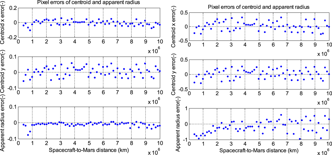
To show the superiority of the proposed identification algorithm to the traditional method with the step model that has been reported (Li et al., Reference Li, Lu, Zhang and Peng2013; Du et al., Reference Du, Wang, Chen, Fang and Su2016), the pixel errors of the centroid and apparent radius during the Mars approach phase are shown in Figure 16. Here, the results of the line-of-sight and apparent radius extractions obtained by these two methods are compared. It can be seen that the pixel errors of our proposed hybrid method can reach about 0·1 pixels which are better than that of the traditional method with the step model. The proposal benefits from the modification of moment-based sub-pixel edge detection and improvement of direct least-square fitting approaches.
Pixel errors of centroid and apparent radius using (left) our hybrid algorithm, and (right) the algorithm based on step model (Li et al., Reference Li, Lu, Zhang and Peng2013; Du et al., Reference Du, Wang, Chen, Fang and Su2016).

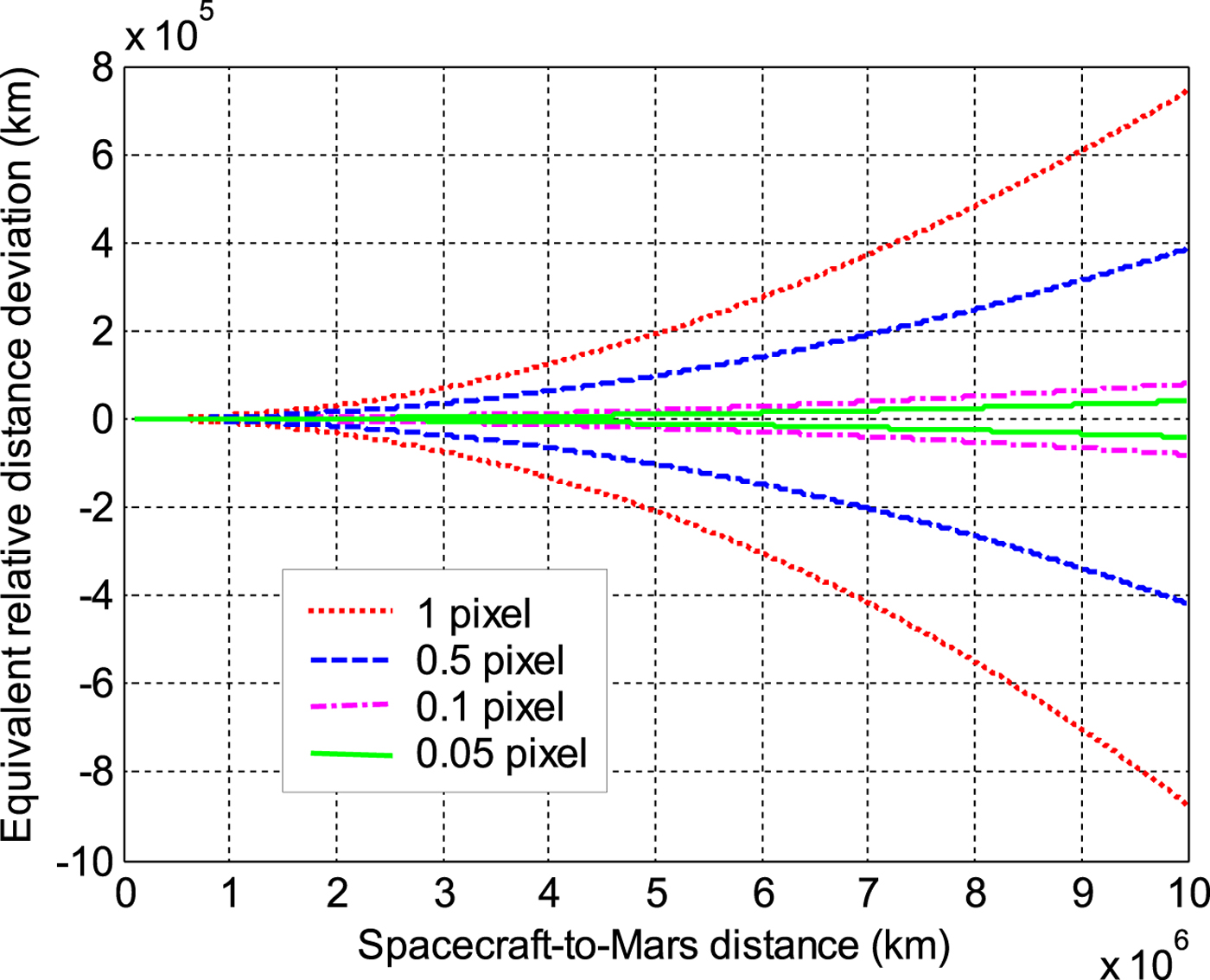
To clarify the influence of the apparent radius accuracy on AutoNav, equivalent relative distance deviations are calculated and compared in Figure 17 and Table 2. As shown in Figure 17, from a large relative distance to close, all the equivalent relative distance deviations corresponding to the pixel errors of the apparent radius are convergent. However, even for the apparent radius accuracy of 0·05 pixels, a huge and unacceptable equivalent distance deviation still exists at the distance of 107 km. Until the spacecraft and Mars are closer than several 105 km (that is, typical Mars capture phase), the subpixel-level apparent radius extraction may be helpful for autonomous localisation. Therefore, integrated navigation is necessary instead of purely image-based OPNAV.
Equivalent relative distance deviation corresponding to the pixel error of the apparent radius.

Equivalent relative distance deviation corresponding to the pixel error of the apparent radius.

5. CONCLUSIONS
Autonomous Optical Navigation (OPNAV) is a potential scheme for future robotic or manned Mars exploration missions. To meet the accuracy demands for Mars approach navigation, a new hybrid high-precision line-of-sight extraction technique has been developed. Meanwhile, an optical image generation and simulation experiment system was also established for pre-flight system design and verification. In particular, a simple and effective Mars image generation procedure has been developed to create the images in the field-of-view of the spacecraft before the implementation of actual missions. The images are driven by reference flight state and camera parameters. A new line-of-sight extraction technique has been proposed through the modification of moment-based sub-pixel edge detection and improvement of direct least-square fitting approaches. Experimental results demonstrate the effectiveness of the established optical image simulation system, and the accuracy of the proposed hybrid line-of-sight extraction algorithm can reach sub-pixel level (about 0·1 pixels) which is better than that in Li et al. (Reference Li, Lu, Zhang and Peng2013) and Du et al. (Reference Du, Wang, Chen, Fang and Su2016). However, if using purely image-based OPNAV including subpixel-level line-of-sight extraction it will still be difficult to meet the needs of navigation accuracy at a large relative distance. Therefore, integrated optical navigation approaches will be our future work.
ACKNOWLEDGMENTS
This work is supported by the National Natural Science Foundation of China (Grant No. 11672126), the Opening Grant from the Key Laboratory of Space Utilization, Chinese Academy of Sciences (LSU-2016-04-01), Postgraduate Research and Practice Innovation Funding of Jiangsu Province (Grant No. KYZZ16_0170), the Fundamental Research Funds for the Central Universities, and Funding for Outstanding Doctoral Dissertation in NUAA (Grant No. BCXJ16-10). The first author would like to acknowledge the financial support provided by the China Scholarship Council for his study at the University of Arizona (Grant No. 201706830055).