1 Introduction
The phenomenon of flow-induced vibration (FIV) is ubiquitous and has many practical applications in structural and marine engineering. It has been a topic of several research investigations in the past. One type of flow-induced vibration that is usually associated with bluff bodies is vortex-induced vibration (VIV), wherein, the unsteady forces experienced by the structure arise from the phenomenon of vortex shedding. Traditionally, the motivation to study VIV has been the need to eliminate/attenuate the vibration. For example, VIV of oil-risers/chimneys may lead to fatigue damage and, in some cases, to even catastrophic failures. VIV has also been utilized to harvest energy from the flow currents along the sea bed (Raghavan et al.
Reference Raghavan, Ben-Simon, Garcia and Bernistas2008, Reference Raghavan, Garcia, Bernistas and Ben-Simon2009). These and several other applications of VIV necessitate a detailed understanding of the associated phenomenon especially in the regime where the structure undergoes large amplitude vibration. The extent of the velocity regime associated with large amplitude vibration depends strongly on the mass of the structure; lower the structural mass, larger is the range of flow velocity over which large amplitude oscillations occur (Khalak & Williamson Reference Khalak and Williamson1999). In the present study we investigate the vortex-induced response of structures that are very light compared to the mass of the fluid that they displace. We especially focus on cases where high amplitude oscillation occurs up to infinite reduced velocity,
 $U^{\ast }$
.
 $U^{\ast }$
is defined as
 $U/f_{N}D$
, where
 $U$
is the free-stream speed and
 $f_{N}$
is the natural frequency of the spring mass system.
 $D$
is the characteristic length of the structure; for example, it is the diameter in case of a cylinder. Owing to its simple geometry, most of the investigations in the past associated with VIV have been carried out for a circular cylinder. Both experimental and computational/analytical methods have been utilized. For a comprehensive review on the various aspects of vortex-induced vibrations, the interested reader is referred to review articles by Bearman (Reference Bearman1984, Reference Bearman2011), Sarpkaya (Reference Sarpkaya2004), Williamson & Govardhan (Reference Williamson and Govardhan2004) and Wu, Ge & Hong (Reference Wu, Ge and Hong2012).
A well-known aspect associated with VIV is the phenomenon of synchronization/lock-in/resonance. In the lock-in regime, the cylinder exhibits large amplitude oscillation. At relatively large Reynolds number (
 $Re\sim 4000{-}30\,000$
), depending on the mass-damping parameter (
 $m^{\ast }\unicode[STIX]{x1D701}$
), the cylinder response, during lock-in may be one of two kinds. The mass ratio,
 $m^{\ast }$
, is defined as the mass of the oscillating structure non-dimensionalized by the mass of the fluid it displaces.
 $\unicode[STIX]{x1D701}$
is the structural damping ratio. The cylinder response is associated with two branches for large
 $m^{\ast }\unicode[STIX]{x1D701}$
: initial and lower. The nomenclature was proposed by Khalak & Williamson (Reference Khalak and Williamson1999). The transition between the initial and lower branch can be either intermittent or hysteretic (Feng Reference Feng1968; Govardhan & Williamson Reference Govardhan and Williamson2000). Compared to large
 $m^{\ast }\unicode[STIX]{x1D701}$
, the response of the cylinder for low
 $m^{\ast }\unicode[STIX]{x1D701}$
values is richer. In this case, three branches of cylinder response exist (Khalak & Williamson Reference Khalak and Williamson1999): initial, upper and lower. The peak amplitude of cylinder oscillation is attained on the upper branch. The transition between the initial and upper branch is hysteretic, while an intermittent behaviour is observed at the boundary between the upper and lower branch (Govardhan & Williamson Reference Govardhan and Williamson2000).
There are significant differences in VIV between the low and high-
 $Re$
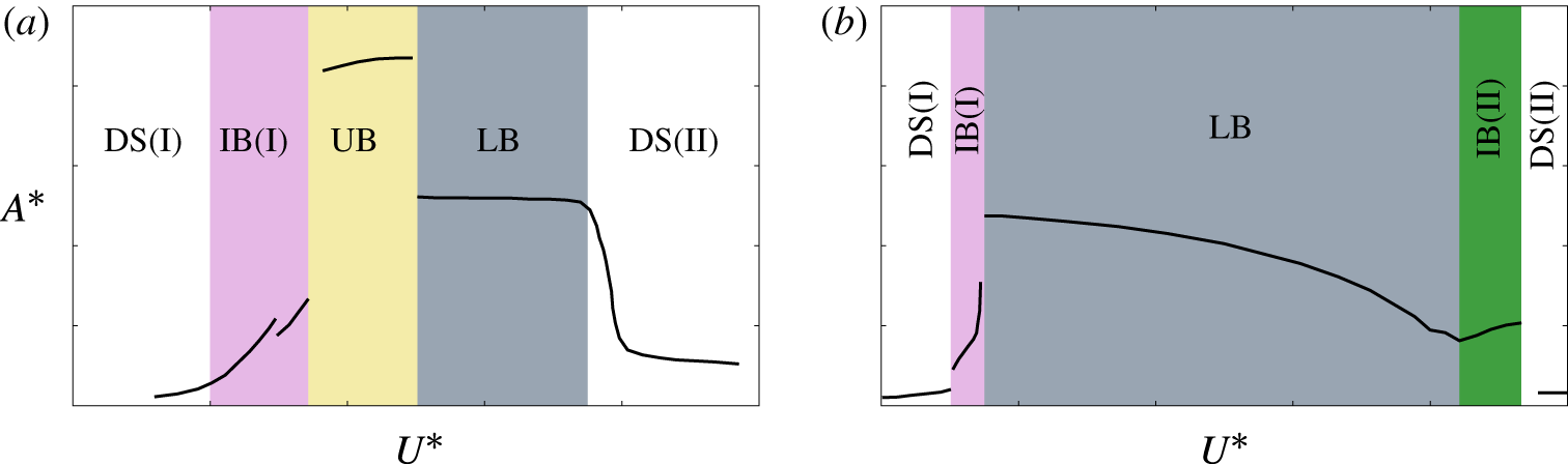
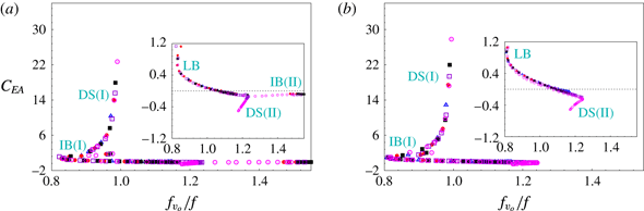
regime. Figure 1 shows the cylinder response in the two regimes for low mass-damping parameter and
 $m^{\ast }\sim 10$
. The various branches during lock-in are highlighted in the figure. The system is in a desynchronized state outside the lock-in regime. These states, for
 $U^{\ast }$
below and above that for lock-in regime are denoted by DS(I) and DS(II), respectively. The peak oscillation amplitude in high-
 $Re$
regime (
 ${\sim}1D$
) is significantly higher than that at low-
 $Re$
(
 ${\sim}0.6D$
). The lock-in response of the cylinder in the laminar flow regime consists of three branches: initial branch I (IB(I)), lower branch (LB) and initial branch II (IB(II)). Of these, IB(I) and LB are fairly well known (Singh & Mittal Reference Singh and Mittal2005; Prasanth & Mittal Reference Prasanth and Mittal2008; Navrose & Mittal Reference Mittal2016). The branch IB(II) has been discovered more recently (Navrose & Mittal Reference Mittal2017) near the higher-
 $U^{\ast }$
end of the lock-in regime. The largest amplitude of cylinder oscillation is achieved on the lower branch. Prasanth, Premchandran & Mittal (Reference Prasanth, Premchandran and Mittal2011) investigated hysteretic versus intermittent transition between IB(I) and LB at low
 $Re$
. Prasanth & Mittal (Reference Prasanth and Mittal2008) reported a jump in the response of the cylinder between the higher-
 $U^{\ast }$
end of the lock-in regime and desynchronization and found it to be hysteretic.
Flow past a freely vibrating cylinder for low mass-damping parameter and
 $m^{\ast }\sim 10$
: schematic of the variation of amplitude with reduced velocity in (a) high-
 $Re$
(Govardhan & Williamson Reference Govardhan and Williamson2000) and (b) laminar flow regime (Prasanth & Mittal Reference Prasanth and Mittal2008). The different branches of response in the lock-in regime are highlighted. DS(I): desynchronization regime I, IB(I): initial branch I, LB: lower branch, UB: upper branch, IB(II): initial branch II, DS(II): desynchronization regime II.

Next, we briefly review the work done in the past to understand the effect of
 $m^{\ast }$
on the response of the cylinder. Khalak & Williamson (Reference Khalak and Williamson1999) and Govardhan & Williamson (Reference Govardhan and Williamson2000, Reference Govardhan and Williamson2006) observed that for systems with similar mass damping parameter, the peak amplitude of cylinder response within the lock-in regime remains nearly the same. The extent of the lock-in regime, however, increases with decrease in
 $m^{\ast }$
. Govardhan & Williamson (Reference Govardhan and Williamson2000) observed that for very low
 $m^{\ast }$
, the lock-in regime can extend up to very large values of reduced velocity. In this situation the frequency ratio,
 $f^{\ast }$
, exhibits very large values on the lower branch.
 $f^{\ast }$
is defined as the ratio of the frequency of the cylinder oscillation to the natural frequency of the oscillator. In contrast, for large
 $m^{\ast }$
,
 $f^{\ast }$
is close to unity within the lock-in regime. By plotting the variation of frequency ratio on the lower branch with
 $m^{\ast }$
, Govardhan & Williamson (Reference Govardhan and Williamson2000) predicted that below the critical mass ratio of
 $m_{crit}^{\ast }=0.54$
, the lower branch ceases to exist and the cylinder response remains on upper branch up to very large values of
 $U^{\ast }$
. The Reynolds number in these experiments varied between
 $1000\leqslant Re\leqslant 10\,000$
. The value of
 $m_{crit}^{\ast }$
was confirmed in a later study by Govardhan & Williamson (Reference Govardhan and Williamson2002), where experiments were carried out without any restraining springs. The absence of springs results in a zero value of
 $f_{N}$
; correspondingly, the reduced velocity is infinity. For
 $m^{\ast }\geqslant 0.54$
, the cylinder exhibits oscillations of very low amplitude. However, for
 $m^{\ast }<0.54$
, large amplitude of cylinder oscillations are observed. Using flow visualization, they observed that the mode of vortex shedding for
 $m^{\ast }<m_{crit}^{\ast }$
resembles the mode that is associated with the upper branch of cylinder response. They, therefore, concluded that for
 $m^{\ast }<m_{crit}^{\ast }$
, lock-in regime persists up to
 $U^{\ast }=\infty$
. This phenomenon was referred to as resonance forever by Govardhan & Williamson (Reference Govardhan and Williamson2002). Morse & Williamson (Reference Morse and Williamson2009a
) carried out experiments to investigate the effect of
 $Re$
on
 $m_{crit}^{\ast }$
. They observed that
 $m_{crit}^{\ast }$
increases with
 $Re$
from a value of
 $0.36$
to
 $0.54$
over the
 $Re$
range
 $4000{-}30\,000$
.
Unlike at large
 $Re$
, there have been very few studies that investigate the response of a freely vibrating structure at very low
 $m^{\ast }$
in the laminar regime. Ryan, Thompson & Hourigan (Reference Ryan, Thompson and Hourigan2005) carried out numerical simulations in the laminar flow regime to investigate free vibration response of a cylinder at
 $U^{\ast }=\infty$
. They presented two regions of
 $Re$
for the existence of
 $m_{crit}^{\ast }$
: higher Reynolds number region (
 $180\leqslant Re\leqslant 200$
) and viscous region (
 $40\leqslant Re\leqslant 95$
). In the higher Reynolds number region, a relatively low value of critical mass ratio was observed (
 $m_{crit}^{\ast }\sim 0.14$
). In the viscous region,
 $m_{crit}^{\ast }$
varies with
 $Re$
. It decreases from
 $m_{crit}^{\ast }\sim 0.5$
at
 $Re=40$
to
 $m_{crit}^{\ast }\sim 0.1$
at
 $Re=95$
. Very low amplitude oscillation of the cylinder was observed up to the lowest mass ratio for
 $100\leqslant Re\leqslant 180$
. Hence, no critical mass was reported in this regime. Their results are in disagreement with Govardhan & Williamson (Reference Govardhan and Williamson2002) who, using the results of Shiels et al. (Reference Shiels, Leonard and Roshko2001), predicted
 $m_{crit}^{\ast }=0.25$
at
 $Re=100$
.
In the present study we explore the critical mass phenomenon in the laminar flow regime in detail. The effect of mass ratio on the extent of the lock-in regime is investigated. We study the transition between LB and DS(II) for low
 $m^{\ast }$
. An attempt is made to bring out the differences in the free vibration response between high-
 $Re$
(Govardhan & Williamson Reference Govardhan and Williamson2000, Reference Govardhan and Williamson2002; Morse & Williamson Reference Morse and Williamson2009a
) and low-
 $Re$
regime for low
 $m^{\ast }$
. To aid this, computations are also carried out to determine
 $m_{crit}^{\ast }$
at a few
 $Re$
beyond the laminar regime. The variation of
 $m_{crit}^{\ast }$
with
 $Re$
ranging from two-dimensional (2-D) flow to the high-
 $Re$
regime is presented.
Earlier studies that investigated the critical mass phenomenon in the high
 $Re$
regime show that the amplitude of cylinder oscillation jumps to relatively large value when
 $m^{\ast }$
is reduced below
 $m_{crit}^{\ast }$
. The present study shows that such a behaviour occurs beyond a particular value of
 $Re$
. This Reynolds number is denoted by
 $Re_{j}$
in this paper. For
 $Re<Re_{j}$
, the amplitude of cylinder vibration increases smoothly with decrease in
 $m^{\ast }$
. In this situation, the criterion of critical mass proposed by Ryan et al. (Reference Ryan, Thompson and Hourigan2005) (
 $m_{crit}^{\ast }=\text{mass}$
ratio for which
 $f_{v_{o}}/f$
at
 $U^{\ast }=\infty$
achieves the highest value) is used to identify the critical mass ratio. Computations are also carried out for finite reduced velocities to investigate the cause for the absence of amplitude jump at
 $U^{\ast }=\infty$
for
 $Re<Re_{j}$
. It is shown that at a given
 $Re$
, the amplitude response for all mass ratios collapse on a curve if plotted against
 $f_{v_{o}}/f$
. A similar observation was made by Khalak & Williamson (Reference Khalak and Williamson1999) and Govardhan & Williamson (Reference Govardhan and Williamson2000) for flow at relatively large
 $Re$
. The present work shows that the collapsed curve depends on the
 $Re$
in the laminar regime. This variation is also presented in this work.
2 The governing equations
The Navier–Stokes equations in primitive variable form are used to model the incompressible fluid flow. The motion of the cylinder, mounted on elastic support, is governed by the following equation
 $$\begin{eqnarray}m\ddot{y} +c{\dot{y}}+ky=F_{y}(t).\end{eqnarray}$$
Here
 $m$
,
 $c$
and
 $k$
are constant and represent the mass of the cylinder, structural damping and spring stiffness. The effect of nonlinearity of the spring has been studied by Mackowski & Williamson (Reference Mackowski and Williamson2013). They showed that it is possible to widen/reduce the extent of lock-in regime by selecting appropriate properties of the nonlinear spring. In the present work, however, the spring is assumed to be linear.
 $F_{y}(t)$
is the time varying fluid force experienced by the cylinder and
 $y$
is its displacement. The non-dimensional form of (2.1) is:
 $$\begin{eqnarray}\displaystyle \ddot{Y} +4\unicode[STIX]{x03C0}F_{N}\unicode[STIX]{x1D701}{\dot{Y}}+(2\unicode[STIX]{x03C0}F_{N})^{2}Y=\frac{2C_{L}}{\unicode[STIX]{x03C0}m^{\ast }}. & & \displaystyle\end{eqnarray}$$
In (2.2)
 $F_{N}$
is the non-dimensional natural frequency of the oscillator,
 $\unicode[STIX]{x1D701}$
the structural damping ratio and
 $C_{L}$
the instantaneous lift coefficient.
 $F_{N}$
is defined as
 $(f_{N}D/U)$
where,
 $f_{N}$
is the natural frequency of the spring-mass system in vacuum. The reciprocal of
 $F_{N}$
is
 $U^{\ast }$
, the reduced velocity. It is defined as
 $U^{\ast }=1/F_{N}=U/f_{N}D$
. Another parameter of interest is the frequency ratio,
 $f^{\ast }$
. It is defined as the ratio of the frequency of cylinder vibration to the natural frequency of the oscillator in vacuum. The lift force is computed by integrating stresses on the boundary of the cylinder.
 $\ddot{Y}$
,
 ${\dot{Y}}$
and
 $Y$
denote the normalized acceleration, velocity and displacement of the body, respectively, in the transverse direction. The characteristic scales to normalize length, velocity and time are
 $D$
,
 $U$
and
 $D/U$
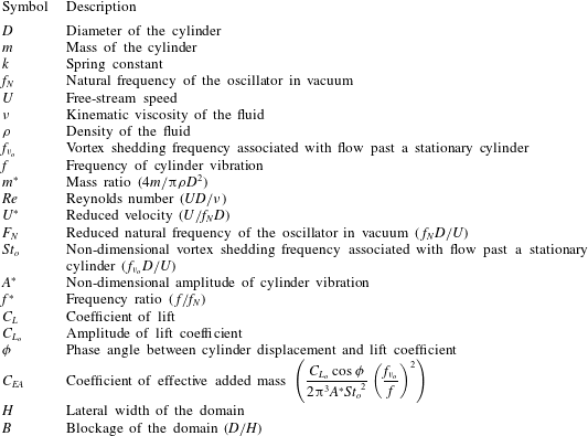
, respectively. Table 1 lists the key symbols used in the paper.
Description of the key symbols.

3 Problem description
The cylinder is rigid and allowed to vibrate transverse to the free-stream flow. To encourage high amplitude oscillation, the structural damping coefficient is set to zero. The Reynolds number is based on the free-stream speed and diameter of the cylinder. Unless stated otherwise, all computations are initiated with the steady flow past a stationary cylinder, at the corresponding
 $Re$
, with the spring in its stretched position in equilibrium with the drag acting on the cylinder. The situation of free vibration in the absence of spring is modelled by setting the natural frequency of the spring to zero. The corresponding reduced speed is infinity. Computations are carried out for
 $0.05\leqslant m^{\ast }\leqslant 10.0$
, over a wide range of
 $U^{\ast }$
, including
 $U^{\ast }=\infty$
. The quantities associated with the response of fluid–structure system at
 $U^{\ast }=\infty$
are tagged with the subscript
 $\infty$
.
3.1 Boundary conditions and numerical method
No-slip condition is applied to the velocity on the surface of the cylinder. Free-stream values are assigned for the velocity at the upstream boundary. The stress vector is set to zero at the downstream boundary. On the lateral boundaries, the normal component of the velocity and tangential component of the stress vector is prescribed a zero value. The location of the cylinder, its velocity and the boundary conditions are updated at each nonlinear iteration of the time marching solution process.
A stabilized space–time finite element method has been utilized to carry out the computations (Tezduyar et al. Reference Tezduyar, Behr, Mittal and Liou1992a ; Tezduyar, Liou & Behr Reference Tezduyar, Liou and Behr1992b ). The detailed description of the finite element formulation used in the present study can be found in Prasanth & Mittal (Reference Prasanth and Mittal2008). The numerical stabilizations are based on SUPG (streamline-upwind/Petrov–Galerkin) and PSPG (pressure-stabilizing/Petrov–Galerkin) techniques (Tezduyar et al. Reference Tezduyar, Mittal, Ray and Shih1992c ). The equation of motion for the oscillator, given by (2.2), is also cast in the space–time formulation as described in the articles by Mittal (Reference Mittal1992) and Mittal & Tezduyar (Reference Mittal and Tezduyar1992).
3.2 Finite element mesh and mesh moving scheme
The cylinder is placed in a rectangular computational domain whose upstream and downstream boundaries are located at
 $L_{u}=10D$
and
 $L_{d}=25.5D$
from the centre of the cylinder. The lateral boundaries are each located at a distance
 $H=10D$
from the cylinder. The finite element mesh used in the computation consists of
 $7437$
nodes and
 $7236$
quadrilateral, four noded elements. It is similar to the one used by Prasanth & Mittal (Reference Prasanth and Mittal2008). A detailed mesh convergence study has been presented in Prasanth & Mittal (Reference Prasanth and Mittal2008) and Navrose et al. (Reference Yogeswaran, Sen and Mittal2014). The effect of blockage of the computational domain is presented in appendix A. The mesh moving scheme has been designed such that the mesh near the cylinder moves along with it like a rigid body while the outer boundary remains fixed. It has been successfully used in our earlier works (Mittal & Kumar Reference Mittal and Kumar1999; Prasanth & Mittal Reference Prasanth and Mittal2008; Prasanth et al.
Reference Prasanth, Premchandran and Mittal2011; Navrose & Mittal Reference Mittal2013). This type of mesh movement method is expected to give almost no projection errors in the solution in the vicinity of the cylinder (Tezduyar et al.
Reference Tezduyar, Behr, Mittal and Liou1992a
,Reference Tezduyar, Liou and Behr
b
).
4 Response of the cylinder in the absence of springs
Free vibration of a cylinder in the absence of the restoring force of the spring is modelled by substituting
 $F_{N}=0$
in (2.2). This situation corresponds to
 $U^{\ast }=\infty$
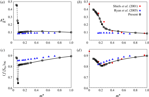
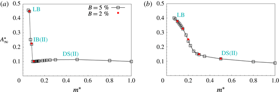
, i.e. infinite reduced velocity. Figure 2(a,c) shows the variation of non-dimensional amplitude and frequency of cylinder oscillation with
 $m^{\ast }$
for such a fluid–structure system at
 $Re=150$
. The amplitude has been non-dimensionalized by the diameter of the cylinder while the frequency has been normalized by the vortex shedding frequency for the flow past a stationary cylinder at the same
 $Re$
. Low amplitude oscillations (
 $A_{\infty }^{\ast }\sim 0.1$
) are observed for
 $m^{\ast }\geqslant 0.09$
. A decrease in the value of
 $m^{\ast }$
from
 $0.09$
to
 $0.08$
results in an abrupt increase in the amplitude of cylinder oscillation (
 $\unicode[STIX]{x0394}A_{\infty }^{\ast }\sim 0.12$
). This change in
 $A_{\infty }^{\ast }$
is accompanied with a sharp decrease in the frequency of cylinder oscillation. With further decrease in
 $m^{\ast }$
,
 $A_{\infty }^{\ast }$
and
 $(f/f_{v_{o}})_{\infty }$
increase gradually before registering another jump at
 $m^{\ast }=0.06$
. Both amplitude and frequency increase across the second jump. For
 $m^{\ast }\leqslant 0.06$
,
 $A_{\infty }^{\ast }$
and
 $(f/f_{v_{o}})_{\infty }$
increase smoothly with decrease in
 $m^{\ast }$
.
Flow past a freely vibrating cylinder in the absence of springs: variation of non-dimensional amplitude and frequency for (a,c)
 $Re=150$
and (b,d)
 $Re=100$
. The data points from numerical simulations carried out by Shiels et al. (Reference Shiels, Leonard and Roshko2001) and Ryan et al. (Reference Ryan, Thompson and Hourigan2005) are also shown. The jumps in the response of the cylinder are shown by broken line. The point corresponding to
 $m_{crit}^{\ast }$
is identified by a solid square.

Govardhan & Williamson (Reference Govardhan and Williamson2002) carried out a similar investigation in the high-
 $Re$
regime (
 $4000\leqslant Re\leqslant 22\,000$
) via experiments. It was observed that the cylinder exhibits low amplitude oscillations for
 $m^{\ast }>0.54$
and undergoes relatively large amplitude oscillations for
 $m^{\ast }\leqslant 0.54$
. They referred to
 $m^{\ast }=0.54$
as the critical mass ratio,
 $m_{crit}^{\ast }$
. The present computations for
 $Re=150$
reveal the critical mass ratio to be
 $0.08$
. In contrast to the high-
 $Re$
regime, which is associated with a single jump in
 $A_{\infty }^{\ast }-m^{\ast }$
(Govardhan & Williamson Reference Govardhan and Williamson2002; Morse & Williamson Reference Morse and Williamson2009a
), the variation at
 $Re=150$
exhibits two jumps (figure 2
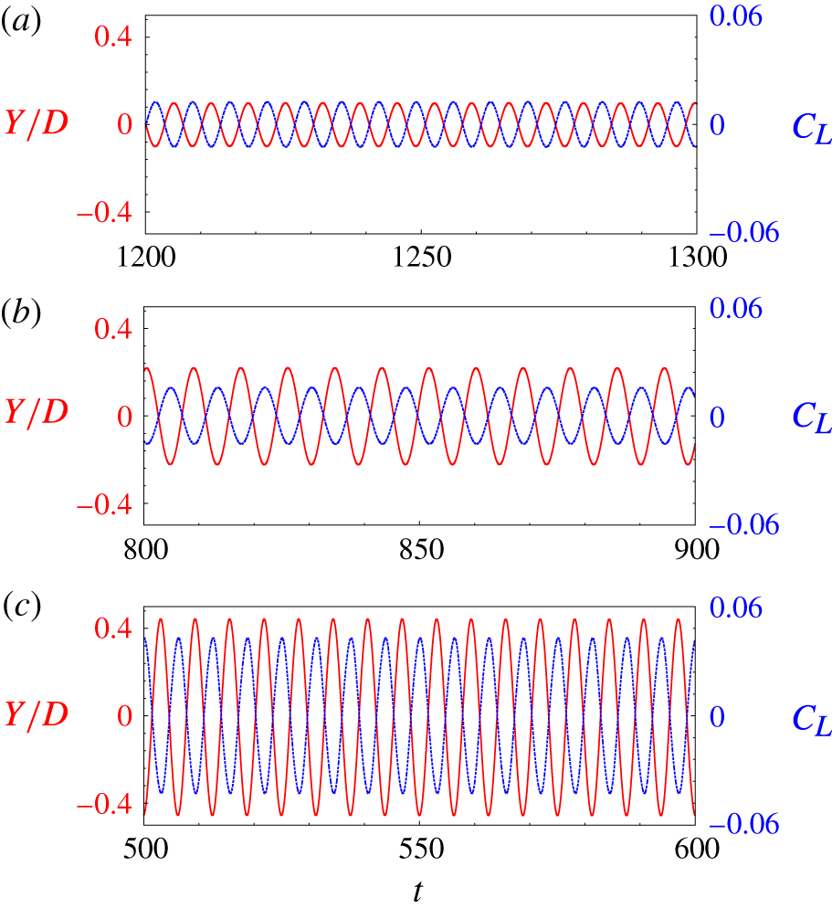
a). Figure 3 shows the time histories of cylinder displacement and lift coefficient for three values of
 $m^{\ast }$
(
 $=0.09$
,
 $0.08$
and
 $0.06$
) that lie on either sides of the two jumps. The increase in
 $A_{\infty }^{\ast }$
and the corresponding
 $C_{L_{o}}$
can be observed from this figure. In all the three cases, the fluid force as well as the cylinder displacement vary nearly sinusoidally with time. The two signals have the same frequency and are out of phase by
 $180^{\circ }$
. Figure 2(a,c) also shows results from the computational study of Ryan et al. (Reference Ryan, Thompson and Hourigan2005). They observed low amplitude oscillations up to the lowest value of
 $m^{\ast }$
that they considered and concluded that critical mass ratio does not exist for
 $Re=150$
.
 $A_{\infty }^{\ast }$
from their study and present work (figure 2
a) are very similar for
 $m^{\ast }\gtrsim 0.08$
. It appears that Ryan et al. (Reference Ryan, Thompson and Hourigan2005) might have observed a jump as well if they had carried out computations for even lower
 $m^{\ast }$
. In the present work we show that large values of
 $A_{\infty }^{\ast }$
are possible for all
 $Re$
at sufficiently low
 $m^{\ast }$
. This is confirmed by carrying out computations at finite
 $U^{\ast }$
for various
 $m^{\ast }$
and utilizing these to estimate the response of the cylinder at
 $U^{\ast }=\infty$
.
 $Re=150$
flow past a freely vibrating cylinder in the absence of springs: time histories of cylinder displacement (red) and lift coefficient (blue) for (a)
 $m^{\ast }=0.09$
, (b)
 $m^{\ast }=0.08$
and (c)
 $m^{\ast }=0.06$
. Time has been non-dimensionalized by the free-stream speed and the diameter of the cylinder.

Figure 2(b,d) shows the variation of
 $A_{\infty }^{\ast }$
and
 $(f/f_{v_{o}})_{\infty }$
with
 $m^{\ast }$
for
 $Re=100$
. Unlike at
 $Re=150$
,
 $A_{\infty }^{\ast }$
increases smoothly with decrease in
 $m^{\ast }$
. No jump is observed in the response of the cylinder. Results from earlier studies (Shiels et al.
Reference Shiels, Leonard and Roshko2001; Ryan et al.
Reference Ryan, Thompson and Hourigan2005) are also shown in the figures. The results from the present study are in good agreement with those from Shiels et al. (Reference Shiels, Leonard and Roshko2001). The results from Ryan et al. (Reference Ryan, Thompson and Hourigan2005) are in reasonable agreement with the present results and those from ?Shiels2001 for
 $m^{\ast }>0.4$
. Similar to
 $Re=150$
, for
 $Re=100$
as well, Ryan et al. (Reference Ryan, Thompson and Hourigan2005) did not observe large amplitude oscillation up to the lowest value of
 $m^{\ast }$
considered in their work. The study of Shiels et al. (Reference Shiels, Leonard and Roshko2001) was carried out for fewer values of
 $m^{\ast }$
. Using this sparse data, Govardhan & Williamson (Reference Govardhan and Williamson2002) predicted a jump in the amplitude response at
 $m^{\ast }=0.25$
and, therefore, reported it as the critical mass ratio for
 $Re=100$
. The results from the present study with significantly more data points shows that variation of
 $A_{\infty }^{\ast }$
with
 $m^{\ast }$
is smooth; there is no perceptible jump. From this, we conclude that for
 $Re=100$
the critical mass ratio cannot be defined via a criterion that is based on a jump in the variation of
 $A_{\infty }^{\ast }$
with
 $m^{\ast }$
.
Flow past a freely vibrating cylinder in the absence of springs: variation of non-dimensional amplitude with mass ratio for different
 $Re$
.

Figure 2 clearly brings out the effect of Reynolds number on the response of the cylinder at
 $U^{\ast }=\infty$
. While the variation of response with
 $m^{\ast }$
for
 $Re=150$
is associated with two jumps, a smooth variation occurs for
 $Re=100$
. To further investigate the effect of
 $Re$
, simulations are carried out for various
 $Re$
in the range
 $60\leqslant Re\leqslant 190$
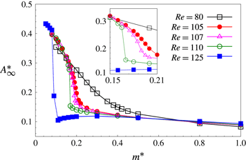
. Figure 4 shows the variation of
 $A_{\infty }^{\ast }$
with
 $m^{\ast }$
for certain
 $Re$
.
 $A_{\infty }^{\ast }$
increases smoothly with decrease in
 $m^{\ast }$
up to the lowest value of
 $m^{\ast }$
considered for
 $Re\leqslant 107$
. On the other hand, for
 $Re\geqslant 110$
, the variation is smooth only for
 $m^{\ast }>m_{crit}^{\ast }$
. The response increases abruptly to relatively large value for
 $m^{\ast }\leqslant m_{crit}^{\ast }$
. For
 $Re\geqslant 125$
the response exhibits an additional jump in the response as the mass ratio is further reduced below
 $m_{crit}^{\ast }$
. Figure 4 suggests that there exists a certain
 $Re$
below which the variation of
 $A_{\infty }^{\ast }$
with
 $m^{\ast }$
is smooth while the response exhibits at least one jump when this
 $Re$
is exceeded. We denote this value of
 $Re$
as
 $Re_{j}$
. The present computations show that
 $Re_{j}$
lies between
 $107$
and
 $110$
.
Motivated by these observations, we explore answers to the following four questions in the rest of the paper.
(i) Why is the variation of
 $A_{\infty }^{\ast }$
with
$m^{\ast }$
associated with jump(s) for
$Re\geqslant Re_{j}$
, while it is smooth for
$Re<Re_{j}$
?
(ii) Is the response of the cylinder at
$U^{\ast }=\infty$
related to that at finite
$U^{\ast }$
? In particular, can the response at finite
$U^{\ast }$
be used to estimate that at
$U^{\ast }=\infty$
?(iii) Variation of
$A_{\infty }^{\ast }$
with
$m^{\ast }$
is devoid of jump for
$Re<Re_{j}$
. Is it possible to identify an alternate criterion to define
$m_{crit}^{\ast }$
for
$Re<Re_{j}$
?(iv) How does
$m_{crit}^{\ast }$
vary with
$Re$
, specifically in the low-
$Re$
regime?


To address (i) and (ii) above we carry out free vibration studies at
 $Re=100$
and
 $150$
covering a wide range of
 $U^{\ast }$
and
 $m^{\ast }$
(
 $0.2\leqslant U^{\ast }\leqslant 100$
,
 $0.05\leqslant m^{\ast }\leqslant 10.0$
). Khalak & Williamson (Reference Khalak and Williamson1999) demonstrated that for the same value of mass-damping parameter, the amplitude response for different
 $m^{\ast }$
collapse in the
 $A^{\ast }-(f_{v_{o}}/f)$
plane.
 $f_{v_{o}}$
is the vortex shedding frequency associated with flow past a stationary cylinder. We utilize this idea to obtain the collapsed data curves at different
 $Re$
in the laminar flow regime. These curves are used to estimate the response at
 $U^{\ast }=\infty$
for a certain
 $m^{\ast }$
. The estimated response is found to be in very good agreement with the direct time integration results for
 $U^{\ast }=\infty$
. The results for finite
 $U^{\ast }$
show that the width of secondary hysteresis increases with decrease in
 $m^{\ast }$
. It is also found that the hysteresis in the cylinder response can continue up to infinite
 $U^{\ast }$
for a certain range of
 $m^{\ast }$
. With respect to the third question, we follow the lead from Ryan et al. (Reference Ryan, Thompson and Hourigan2005) for an alternate definition of critical mass ratio. They defined
 $m_{crit}^{\ast }$
as the mass ratio for which
 $(f/f_{v_{o}})_{\infty }$
achieves the lowest value. For
 $Re>Re_{j}$
, the proposed definition is consistent with the conventional definition of
 $m_{crit}^{\ast }$
based on the jump in
 $A_{\infty }^{\ast }$
. This can be observed from figure 2(a,c) for
 $Re=150$
where
 $m_{crit}^{\ast }$
is associated with the minimum value of
 $(f/f_{v_{o}})_{\infty }$
. Utilizing this definition, we observe from figure 2(d) that for
 $Re=100$
,
 $(f/f_{v_{o}})_{\infty }$
achieves a minimum at
 $m^{\ast }=0.23$
. Therefore, the critical mass ratio, based on the criterion proposed by Ryan et al. (Reference Ryan, Thompson and Hourigan2005), for
 $Re=100$
is
 $m_{crit}^{\ast }=0.23$
. The data points corresponding to
 $m_{crit}^{\ast }$
are shown by solid square in figure 2(a,b). Finally, to address (iv), computations are carried out at various
 $Re$
.
5 Vortex-induced vibration in the presence of a spring
The results presented in § 4 show that there exists a qualitative difference between the response curve for
 $Re=150$
and
 $100$
at
 $U^{\ast }=\infty$
. For
 $Re=150$
, the variation of
 $A_{\infty }^{\ast }$
with
 $m^{\ast }$
exhibits two jumps. On the other hand, for
 $Re=100$
,
 $A_{\infty }^{\ast }$
varies smoothly with
 $m^{\ast }$
(figure 2
b). A question that arises is whether this effect of
 $Re$
occurs only at
 $U^{\ast }=\infty$
or at finite
 $U^{\ast }$
as well. To explore this, we carry out simulations for the flow past a freely vibrating cylinder in the presence of a spring. The reduced velocity is varied between
 $0.2$
and
 $100$
. Several values of mass ratio are considered in the range
 $0.05\leqslant m^{\ast }\leqslant 10.0$
.
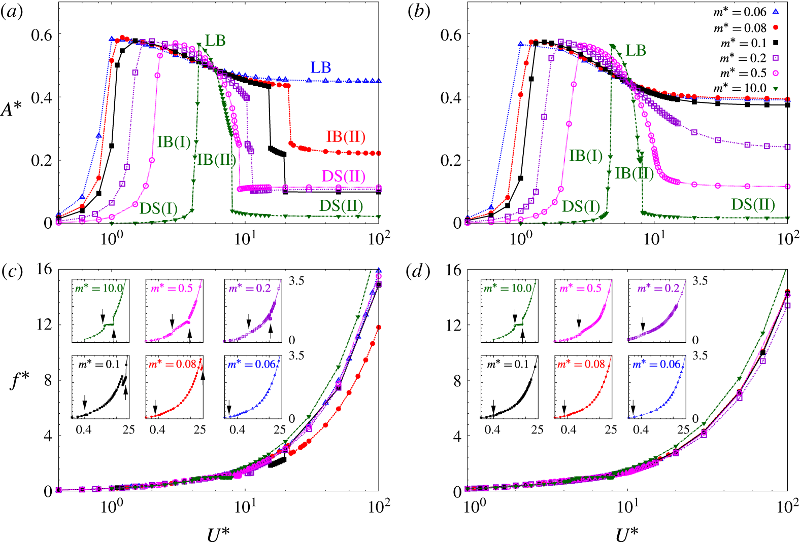
Figure 5(a,b) shows the variation of the fully developed amplitude of cylinder oscillation with reduced speed for
 $Re=150$
and
 $100$
for different mass ratios. Figure 5(c,d) shows the variation of
 $f^{\ast }$
with
 $U^{\ast }$
for the same set of parameters. It is observed that for a given
 $Re$
the maximum
 $A^{\ast }$
is nearly the same for all
 $m^{\ast }$
. This is consistent with earlier findings (Govardhan & Williamson Reference Govardhan and Williamson2006) that peak
 $A^{\ast }$
depends on
 $m^{\ast }\unicode[STIX]{x1D701}$
;
 $\unicode[STIX]{x1D701}$
is zero in the present study. Interestingly, within the range of reduced velocity in which the cylinder exhibits relatively large amplitude of oscillation, there exists a certain
 $U^{\ast }$
at which the amplitude of cylinder response is same for all
 $m^{\ast }$
. For example, for
 $Re=150$
this reduced velocity is
 ${\sim}5.9$
. The frequency of cylinder oscillation at this
 $U^{\ast }$
is found to be independent of
 $m^{\ast }$
as well and its value is close to
 $f_{v_{o}}$
. Khalak & Williamson (Reference Khalak and Williamson1999) introduced the concept of effective added mass in free vibration of bluff bodies. The value of
 $C_{EA}$
(coefficient of effective added mass) for this reduced velocity is found to be equal to zero for all
 $m^{\ast }$
. We denote this reduced velocity by
 $U_{\{C_{EA}=0\}}^{\ast }$
. More discussion on
 $U_{\{C_{EA}=0\}}^{\ast }$
is presented later in the paper and in appendix B.
Flow past a freely vibrating cylinder in the presence of springs: variation of non-dimensional amplitude and
 $f^{\ast }$
with reduced velocity for (a,c)
 $Re=150$
and (b,d)
 $Re=100$
. The jumps in the frequency response of the cylinder is shown via arrows in the insets of (c,d).

To aid the discussion, we refer to
 $m^{\ast }\leqslant 0.06$
as small and
 $m^{\ast }\geqslant 2.0$
as large. Furthermore, the range
 $0.06<m^{\ast }<2.0$
is referred to as moderate/intermediate. We first consider the large
 $m^{\ast }$
case. In this range of
 $m^{\ast }$
, the response of the cylinder for
 $Re=150$
and
 $100$
is qualitatively similar in terms of jump in the variation of
 $A^{\ast }$
and
 $f^{\ast }$
with
 $U^{\ast }$
. The response curves are associated with two jumps. The jumps are better identified from the variation of
 $f^{\ast }$
with
 $U^{\ast }$
. They are marked by vertical line segments with arrows in the insets of figure 5(c,d). The first jump is shown by a downward pointing arrow, and the second one is shown by an upward pointing arrow. Also marked in figure 5(a,b) are the various branches of cylinder response for
 $m^{\ast }=10.0$
. The first jump occurs between IB(I) and LB, and the second jump takes place between IB(II) and regime DS(II). The branch IB(II) is a relatively recent discovery, and is found to exist near the higher-
 $U^{\ast }$
end of the lock-in regime (Navrose & Mittal Reference Mittal2017). The jumps in the response curve can also be used to identify the approximate extent of the lock-in regime. The value of
 $f^{\ast }$
within the lock-in regime is close to unity. Outside the lock-in regime, the cylinder exhibits low amplitude of oscillation and
 $f^{\ast }$
increases with increase in
 $U^{\ast }$
. The extent of lock-in regime is similar for
 $Re=150$
and
 $100$
.
Next, we consider free vibration for small mass ratio (
 $m^{\ast }=0.06$
). Unlike for
 $m^{\ast }=10.0$
, only one jump is observed in the response of the cylinder. This corresponds to the transition between IB(I) and LB. The behaviour is similar for
 $Re=150$
and
 $100$
. In the insets of figure 5(c,d) this jump is shown by a downward pointing arrow. Beyond the IB(I)–LB transition, the response of the cylinder remains on the lower branch up to the largest value of
 $U^{\ast }$
that has been considered. The value of
 $f^{\ast }$
on LB increases with increase in reduced speed, achieving a value of
 ${\sim}16$
for
 $U^{\ast }=100$
. This is markedly different compared to the behaviour at large
 $m^{\ast }$
, where the lower branch is associated with near unity value of
 $f^{\ast }$
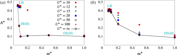
. Figure 6(a,b) shows the variation of
 $A^{\ast }$
with
 $m^{\ast }$
for various
 $U^{\ast }$
at
 $Re=150$
and
 $100$
, respectively. It is observed that
 $U^{\ast }=100$
is a very good approximation to
 $U^{\ast }=\infty$
for all
 $m^{\ast }$
; the amplitude of cylinder vibration for the two reduced speeds are very close. The difference in the value of
 $A^{\ast }$
for
 $U^{\ast }=\infty$
and
 $100$
for
 $m^{\ast }=0.06$
is less than
 $1\,\%$
. We, therefore, conclude that LB extends up to
 $U^{\ast }=\infty$
for
 $m^{\ast }=0.06$
. This scenario corresponds to resonance/lock-in forever. The phrase resonance forever was introduced by Govardhan & Williamson (Reference Govardhan and Williamson2002) in relation to experiments carried out at large
 $Re$
(
 $4000\leqslant Re\leqslant 22\,000$
). We note a difference in the phenomenon at low and high-
 $Re$
. In the high-
 $Re$
regime, the response of the cylinder for
 $m^{\ast }\leqslant m_{crit}^{\ast }$
continues on the upper branch up to
 $U^{\ast }=\infty$
(Govardhan & Williamson Reference Govardhan and Williamson2002). However, in the laminar regime, the upper branch does not exist (figure 1). The response for
 $m^{\ast }\leqslant m_{crit}^{\ast }$
, in this situation, remains on the lower branch up to
 $U^{\ast }=\infty$
.
Flow past a freely vibrating cylinder: variation of amplitude of cylinder oscillation with mass ratio at various reduced speeds for (a)
 $Re=150$
and (b)
 $Re=100$
.

For intermediate values of
 $m^{\ast }$
, the response curve for
 $Re=150$
and
 $100$
(see figure 5
a–d) are qualitatively similar at low
 $U^{\ast }$
but different at large
 $U^{\ast }$
. In low-
 $U^{\ast }$
regime (
 $U^{\ast }\lesssim U_{\{C_{EA}=0\}}^{\ast }$
), the response of the cylinder for both the
 $Re$
transits from regime DS(I) to IB(I) and then to LB with increase in
 $U^{\ast }$
. In large-
 $U^{\ast }$
regime (
 $U^{\ast }\gtrsim U_{\{C_{EA}=0\}}^{\ast }$
), the response for
 $Re=150$
may exhibit either one or two jumps depending on
 $m^{\ast }$
. For example, for
 $m^{\ast }=0.08$
the response jumps from LB to IB(II) and remains on IB(II) up to
 $U^{\ast }=100$
. As the response for
 $U^{\ast }=\infty$
is very similar to that for
 $U^{\ast }=100$
(figure 6
a), IB(II) continues up to
 $U^{\ast }=\infty$
for
 $(Re,m^{\ast })=(150,0.08)$
. This situation corresponds to resonance forever as well, albeit on a different branch of cylinder response as compared to
 $m^{\ast }=0.06$
. For
 $m^{\ast }\geqslant 0.09$
, two jumps exist in the large-
 $U^{\ast }$
regime. The first jump corresponds to the transition between LB and IB(II) while the other occurs between IB(II) and regime DS(II). The amplitude of cylinder oscillation in regime DS(II) remains nearly constant with
 $U^{\ast }$
. The magnitude of jump in
 $A^{\ast }$
between LB and IB(II) is found to decrease with increase in
 $m^{\ast }$
. The jump disappears for
 $m^{\ast }$
beyond
 $0.5$
and the response transits smoothly from LB to IB(II). Unlike for
 $Re=150$
, the response of the cylinder for
 $Re=100$
varies smoothly with increase in
 $U^{\ast }$
beyond the IB(I)–LB transition. In this situation, there is no demarcation via an amplitude/frequency jump between the lock-in and desynchronization regime.
Flow past a freely vibrating cylinder in the presence of springs: variation of non-dimensional amplitude with
 $f_{v_{o}}/f$
for various mass ratios at (a)
 $Re=150$
and (b)
 $Re=100$
. The collapsed amplitude curve is shown in broken lines in the two panels.

We now attempt to address the first of the four questions that were posed towards the end of § 4. For
 $Re\geqslant Re_{j}$
, the response of the cylinder for
 $m^{\ast }>m_{crit}^{\ast }$
lies in regime DS(II) at large
 $U^{\ast }$
and is characterized by low amplitude of oscillation. However, for
 $m^{\ast }\leqslant m_{crit}^{\ast }$
, the fluid–structure system remains in a state of lock-in up to
 $U^{\ast }=\infty$
. The cylinder exhibits relatively large amplitude of oscillation. We, therefore, conclude that the jump in
 $A_{\infty }^{\ast }$
at
 $m_{crit}^{\ast }$
(figure 2
a) is a fallout of the cylinder response moving from regime DS(II) to a lock-in state. This, as shown in figure 5(a), is largely a consequence of jump in
 $A^{\ast }$
between lock-in and DS(II) regime and its value remaining virtually constant in DS(II). For
 $m^{\ast }\leqslant m_{crit}^{\ast }$
, the response at
 $U^{\ast }=\infty$
depends on the branch associated with resonance forever. For
 $Re=150$
, depending on
 $m^{\ast }$
, the response may be on either IB(II) or LB. Compared to LB, IB(II) is associated with lower amplitude and frequency of cylinder vibration. The transition between the two branches is associated with a jump in the amplitude of the response of the cylinder as is also evident from figure 5(a). Therefore, the second jump in
 $A_{\infty }^{\ast }$
, that occurs for a mass ratio below
 $m_{crit}^{\ast }$
, is an outcome of the response shifting from IB(II) to LB with decrease in
 $m^{\ast }$
. For lower
 $Re$
(e.g.
 $Re=110$
), IB(II) does not exist and the second jump does not occur. The response, in this situation, jumps directly from regime DS(II) to LB. For
 $Re<Re_{j}$
the amplitude of cylinder oscillation in large-
 $U^{\ast }$
regime increases smoothly with decrease in
 $m^{\ast }$
(figure 6
b). Consequently,
 $A_{\infty }^{\ast }$
for
 $Re<Re_{j}$
increases smoothly with decrease in
 $m^{\ast }$
(figure 4) and is devoid of any jump.
6 Collapse of free vibration data for various
$m^{\ast }$

6.1 Collapsed amplitude curve (CAC) and collapsed
$C_{EA}$
curve (CCC)

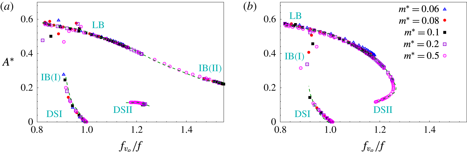
The data in figure 5 are re-plotted in figure 7(a,b) to show the variation of
 $A^{\ast }$
with
 $f_{v_{o}}/f$
for different mass ratios at
 $Re=150$
and
 $100$
. Low to moderate values of
 $m^{\ast }$
are considered. Similar to the high-
 $Re$
regime (reported by Khalak & Williamson (Reference Khalak and Williamson1999)), the amplitude data in the low
 $Re$
regime also show an excellent collapse. We refer to the curve formed from the collapsed amplitude data as collapsed amplitude curve (CAC). In figure 7(a,b), the CAC for
 $Re=150$
and
 $Re=100$
are shown using broken lines. The desynchronization regimes and the different branches of cylinder response are marked on the two CACs. The CAC for
 $Re=150$
is associated with two discontinuities. They correspond to IB(I)–LB and IB(II)–DS(II) transitions. Interestingly, the CAC shows a smooth variation between LB and IB(II) despite the response curves exhibiting a jump between LB and IB(II) in figure 5(a). This is attributed to the change in the nature of transition between LB and IB(II) with
 $m^{\ast }$
. For large
 $m^{\ast }$
(e.g.
 $m^{\ast }=0.5$
), the transition is smooth while for low
 $m^{\ast }$
(e.g.
 $m^{\ast }=0.1$
) the transition is associated with a jump in the response of the cylinder. The CAC shown in figure 7(a) is obtained from the union of data points for various
 $m^{\ast }$
and is, therefore, continuous between LB and IB(II). The CAC for
 $Re=100$
exhibits only one discontinuity. It corresponds to the IB(I)–LB transition. The absence of second discontinuity is consistent with figure 5(b) where no jump is observed in the large-
 $U^{\ast }$
regime. The response transits smoothly from LB to DS(II)-like response. The branch IB(II) does not exists for
 $Re=100$
.
Flow past a freely vibrating cylinder in the presence of springs: variation of effective added mass coefficient with
 $f_{v_{o}}/f$
for various mass ratios at (a)
 $Re=150$
and (b)
 $Re=100$
. Symbols are the same as figure 7.

Forced vibration studies carried out by Hover, Techet & Triantafyllou (Reference Hover, Techet and Triantafyllou1998), Leontini et al. (Reference Leontini, Stewart, Thompson and Hourigan2005) and Morse & Williamson (Reference Morse and Williamson2009b
) show that the effective added mass coefficient (
 $C_{EA}$
) of an oscillating cylinder depends only on
 $f_{v_{o}}/f$
. Therefore, similar to
 $A^{\ast }$
,
 $C_{EA}$
for various mass ratios also show a collapse if plotted against
 $f_{v_{o}}/f$
. We refer to the curve for
 $C_{EA}$
as collapsed
 $C_{EA}$
curve (CCC). Figure 8(a,b) shows CCC for
 $Re=150$
and
 $100$
, respectively.
Flow past a freely vibrating cylinder: variation of (a) CAC and (b) CCC with
 $Re$
.

Unlike at relatively large-
 $Re$
, where CAC and CCC are virtually independent of
 $Re$
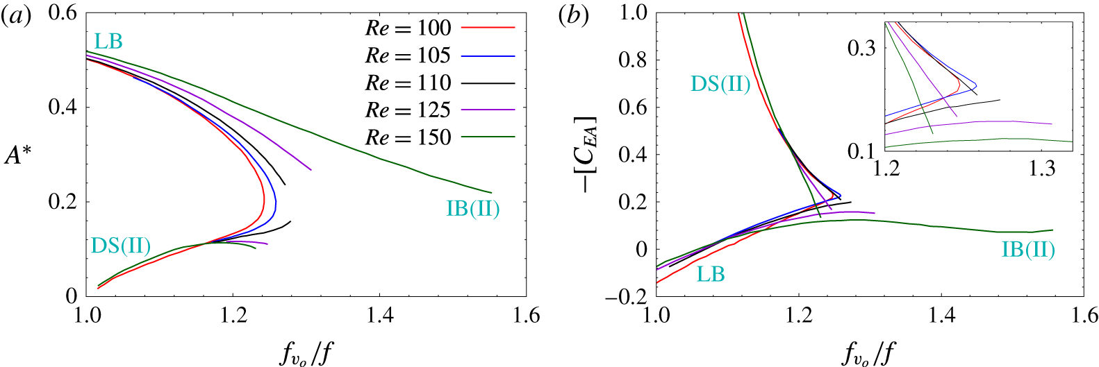
, the collapsed curves in the laminar regime are found to vary with
 $Re$
. Figure 9(a,b) shows CAC and CCC for different
 $Re$
. The various branches of cylinder response and regime DS(II) have been marked in the two figures. A smooth transition from LB to DS(II) occurs for low
 $Re$
. For intermediate
 $Re$
(for example,
 $Re=110$
), the collapsed curves exhibit a discontinuity in the transition between LB and DS(II). For higher
 $Re$
, the lock-in regime includes an additional branch: IB(II). The transition between IB(II) and DS(II) is associated with a discontinuity in the two collapsed curves. It is observed that while
 $A^{\ast }$
and
 $f_{v_{o}}/f$
change significantly across the jumps,
 $C_{EA}$
values on either side of the jumps are very close. This observation is related to the jump in the value of
 $A_{\infty }^{\ast }$
and
 $(f_{v_{o}}/f)_{\infty }$
at
 $m_{crit}^{\ast }$
for
 $Re\geqslant Re_{j}$
, and is discussed in detail in the following section.
6.2 Response for
$U^{\ast }=\infty$

The collapsed data curves for
 $A^{\ast }$
and
 $C_{EA}$
, for the specific
 $Re$
, can be used to predict the response of a freely vibrating cylinder for any value of
 $U^{\ast }$
, including
 $U^{\ast }=\infty$
. The procedure for such an estimation for finite
 $U^{\ast }$
, in the high-
 $Re$
regime, can be found in the work by Staubli (Reference Staubli1983), Hover et al. (Reference Hover, Techet and Triantafyllou1998) and Morse & Williamson (Reference Morse and Williamson2009b
). In the rest of the paper we focus on that part of CAC and CCC which corresponds to
 $f_{v_{o}}/f\geqslant 1$
. As shown later in this section, the other part of the collapsed curve is not relevant for estimating the cylinder response at
 $U^{\ast }=\infty$
.
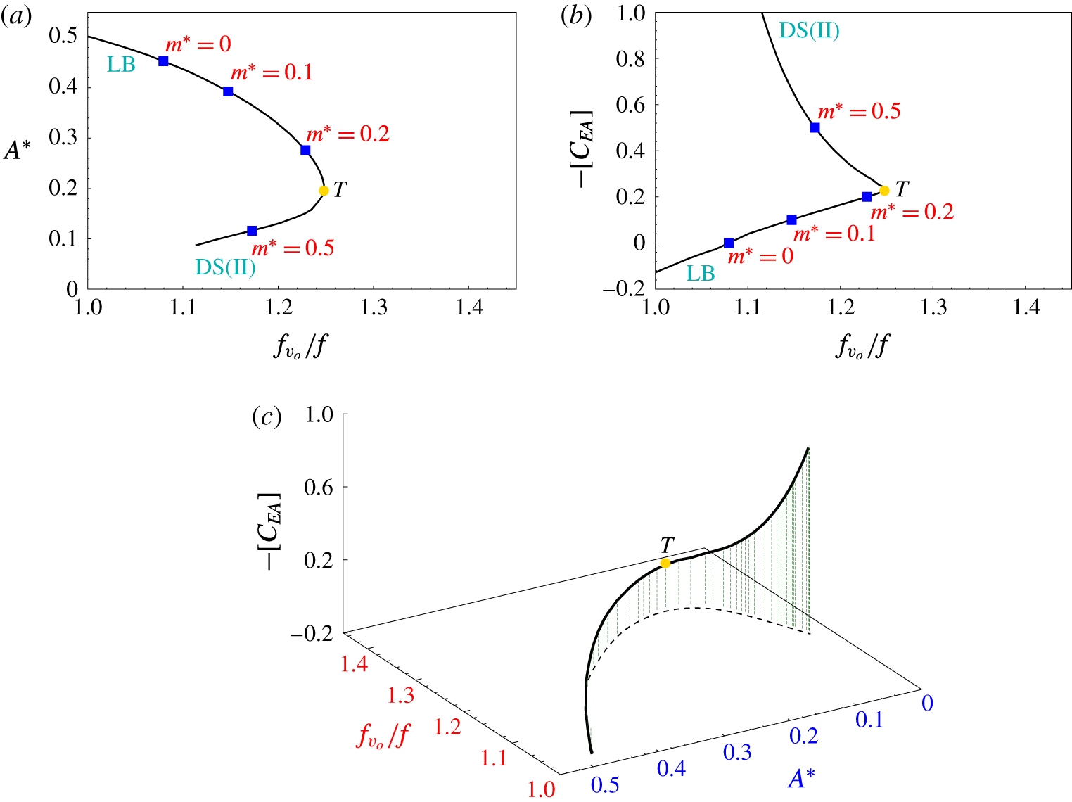
Figure 10(a,b) shows the CAC and CCC for
 $Re=100$
. The two curves are used to generate a three-dimensional plot that shows the variation of
 $C_{EA}$
with
 $(f_{v_{o}}/f)$
and
 $A^{\ast }$
. It is shown in figure 10(c). Govardhan & Williamson (Reference Govardhan and Williamson2002) showed that free vibration of a bluff body in the absence of restoring force satisfies the frequency equation:
 $m^{\ast }=[-C_{EA}]$
. We utilize this relation and the collapsed data curves to estimate the response of cylinder for
 $U^{\ast }=\infty$
. For any
 $m^{\ast }$
, we set
 $[-C_{EA}]=m^{\ast }$
and obtain the corresponding value of
 $(f_{v_{o}}/f)$
and
 $A^{\ast }$
from figure 10(c) (or from figure 10
a,b). The estimated response of the cylinder at
 $U^{\ast }=\infty$
for few mass ratios are shown as solid squares in figure 10(a,b). The estimated values are found to be in excellent agreement with the computed value shown in figure 2(b,d).
 $Re=100$
flow past a freely vibrating cylinder: (a) collapsed amplitude curve and (b) collapsed
 $C_{EA}$
curve (CCC). The value of
 $A^{\ast }$
and
 $-[C_{EA}]$
at
 $U^{\ast }=\infty$
for different mass ratios is shown with blue solid squares. (c) A three-dimensional plot depicting the variation of effective added mass coefficient with
 $(f_{v_{o}}/f)$
and
 $A^{\ast }$
.

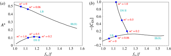
Figure 11(a,b) shows the CAC and CCC for
 $Re=150$
. Unlike at
 $Re=100$
, the collapsed data curves for
 $Re=150$
are associated with discontinuities that separate the lower branch of cylinder response from the regime DS(II). We use the same procedure as proposed earlier for
 $Re=100$
to estimate the response of the cylinder at
 $U^{\ast }=\infty$
for
 $Re=150$
for various
 $m^{\ast }$
. The estimated response is marked in figure 11 by solid squares. For
 $m^{\ast }\leqslant 0.1$
, the response of the cylinder lies on the lower branch. With increase in the value of
 $m^{\ast }$
from
 $0.1$
to
 $0.2$
the response shifts to regime DS(II). This transition is associated with a jump in the amplitude and frequency of cylinder vibration.
 $Re=150$
flow past a freely vibrating cylinder: (a) collapsed amplitude curve (CAC) and (b) collapsed
 $C_{EA}$
curve (CCC). The value of
 $A^{\ast }$
and
 $-[C_{EA}]$
at
 $U^{\ast }=\infty$
for different mass ratios is shown with blue solid squares.

The response of a freely vibrating cylinder for the interesting case of
 $\{U^{\ast },m^{\ast }\}=\{\infty ,0\}$
is estimated by setting
 $[-C_{EA}]$
equal to zero. A discussion on this is presented in appendix B. It is observed from figures 10 and 11 that
 $A_{\infty }^{\ast }$
achieves its maximum value at
 $m^{\ast }=0$
. A question comes up: at each
 $Re$
, does this represent the maximum
 $A^{\ast }$
that one can expect for any
 $U^{\ast }$
? In the high-
 $Re$
regime,
 $A^{\ast }$
for
 $\{U^{\ast },m^{\ast }\}=\{\infty ,0\}$
represents the largest amplitude of oscillation that can be achieved in free vibration for any
 $U^{\ast }$
and
 $m^{\ast }$
(Horowitz & Williamson Reference Horowitz and Williamson2010). However, this is not the case for low-
 $Re$
VIV. For example, the maximum amplitude of cylinder response at
 $Re=100$
is
 ${\sim}0.59D$
(figure 5
b). The
 $A_{\infty }^{\ast }$
at this
 $Re$
for
 $m^{\ast }=0$
is
 $0.45$
. Similar observation is made for the
 $Re=150$
flow as well. Figure 12(a,b) shows the variation of amplitude and
 $(f_{v_{o}}/f)$
for
 $\{U^{\ast },m^{\ast }\}=\{\infty ,0\}$
with
 $Re$
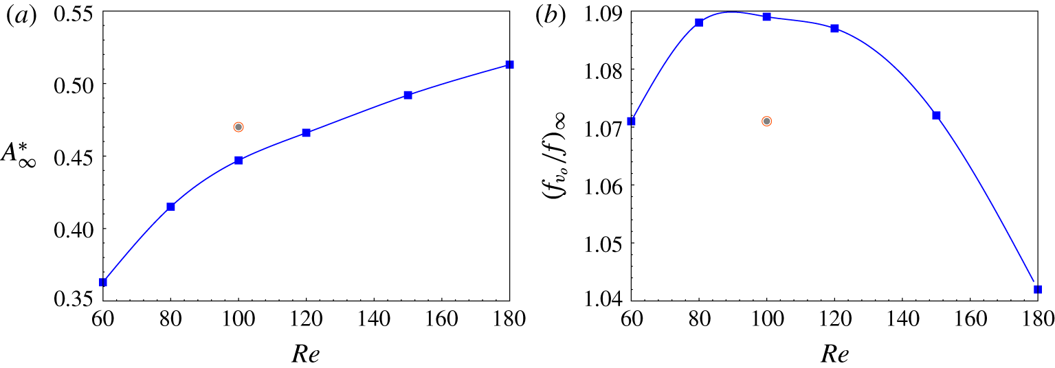
. The data point from Shiels et al. (Reference Shiels, Leonard and Roshko2001) is also shown. It is observed that
 $A_{\infty }^{\ast }$
increases with increase in
 $Re$
. The value of
 $(f_{v_{o}}/f)_{\infty }$
, on the other hand, shows a non-monotonic variation. It increases with Reynolds number up to
 $Re=100$
. Beyond
 $Re=100$
,
 $(f_{v_{o}}/f)_{\infty }$
decreases with increase in
 $Re$
. In general, the value of
 $(f_{v_{o}}/f)_{\infty }$
remains close to but slightly greater than unity. We note that the equation
 $m^{\ast }=[-C_{EA}]$
suggests a negative value of
 $m^{\ast }$
for positive
 $C_{EA}$
. This is unphysical for free vibrations. Therefore, the part of CCC associated with positive
 $C_{EA}$
is not considered for estimating the cylinder response at
 $U^{\ast }=\infty$
.
Flow past a freely vibrating cylinder for
 $\{U^{\ast },m^{\ast }\}=\{\infty ,0\}$
: variation of (a) non-dimensional amplitude and (b) frequency ratio with
 $Re$
. The data points from Shiels et al. (Reference Shiels, Leonard and Roshko2001) are shown using the bull’s eye symbol.

7 Hysteresis for
$Re\geqslant Re_{j}$

7.1 Multiple states at
$U^{\ast }=\infty$

Some studies in the past have shown that a jump in the response of the cylinder, in the laminar regime, is associated with hysteresis (Singh & Mittal Reference Singh and Mittal2005; Prasanth & Mittal Reference Prasanth and Mittal2008; Prasanth et al.
Reference Prasanth, Premchandran and Mittal2011; Navrose et al.
Reference Yogeswaran, Sen and Mittal2014). We explore possible hysteresis in the jump(s) in the response at
 $U^{\ast }=\infty$
for
 $Re\geqslant Re_{j}$
. To this extent, computations are carried out at
 $Re=150$
for various
 $m^{\ast }$
via four different approaches. These are described below.
(i) Steady: computation for each
$m^{\ast }$
is initiated with the
$Re=150$
steady flow past a stationary cylinder. The response curve obtained using this approach is shown in figure 2(a).(ii) Decreasing
$m^{\ast }$
: first, the solution for
$m^{\ast }=1.0$
is obtained via the steady approach. Starting from this solution as the initial condition, mass ratio is decreased in small decrements. The fully developed solution at each
$m^{\ast }$
is computed and utilized as an initial condition for the next decremented value of
$m^{\ast }$
.(iii) Increasing
$m^{\ast }$
: mass ratio is increased in small increments starting from the solution for
$m^{\ast }=0.05$
that is obtained via the steady approach. The fully developed solution at each
$m^{\ast }$
is utilized as initial condition for the next incremented value for
$m^{\ast }$
.(iv) Increasing
$m^{\ast }$
, from
$m^{\ast }=0.07$
: similar to increasing
$m^{\ast }$
approach. However, the starting state is for
$m^{\ast }=0.07$
that lies on the branch IB(II). It is obtained via the steady approach.


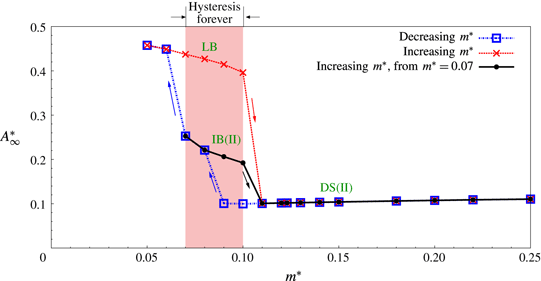
 $Re=150$
flow past a freely vibrating cylinder at
 $U^{\ast }=\infty$
: hysteresis in the amplitude response of the cylinder.

The results from the various approaches are summarized in figure 13. The steady and decreasing
 $m^{\ast }$
approach result in identical states for each
 $m^{\ast }$
. Therefore, to avoid clutter, the response curve from the steady approach is not shown in the figure. With these two approaches the response of the cylinder lies on DS(II) for
 $m^{\ast }>0.08$
, IB(II) for
 $0.07\leqslant m^{\ast }\leqslant 0.08$
and LB for
 $m^{\ast }<0.07$
. Compared to the decreasing
 $m^{\ast }$
approach, the increasing
 $m^{\ast }$
approach results in different states of the cylinder response for a certain range of
 $m^{\ast }$
. The solution obtained via the increasing
 $m^{\ast }$
approach remains on LB up to
 $m^{\ast }=0.1$
and then directly transits to DS(II), bypassing IB(II). The simulations with the increasing
 $m^{\ast }$
, from
 $m^{\ast }=0.07$
approach also lead to very interesting results. With this approach the solution remains on IB(II) up to
 $m^{\ast }=0.1$
and then transitions to DS(II) for higher
 $m^{\ast }$
.
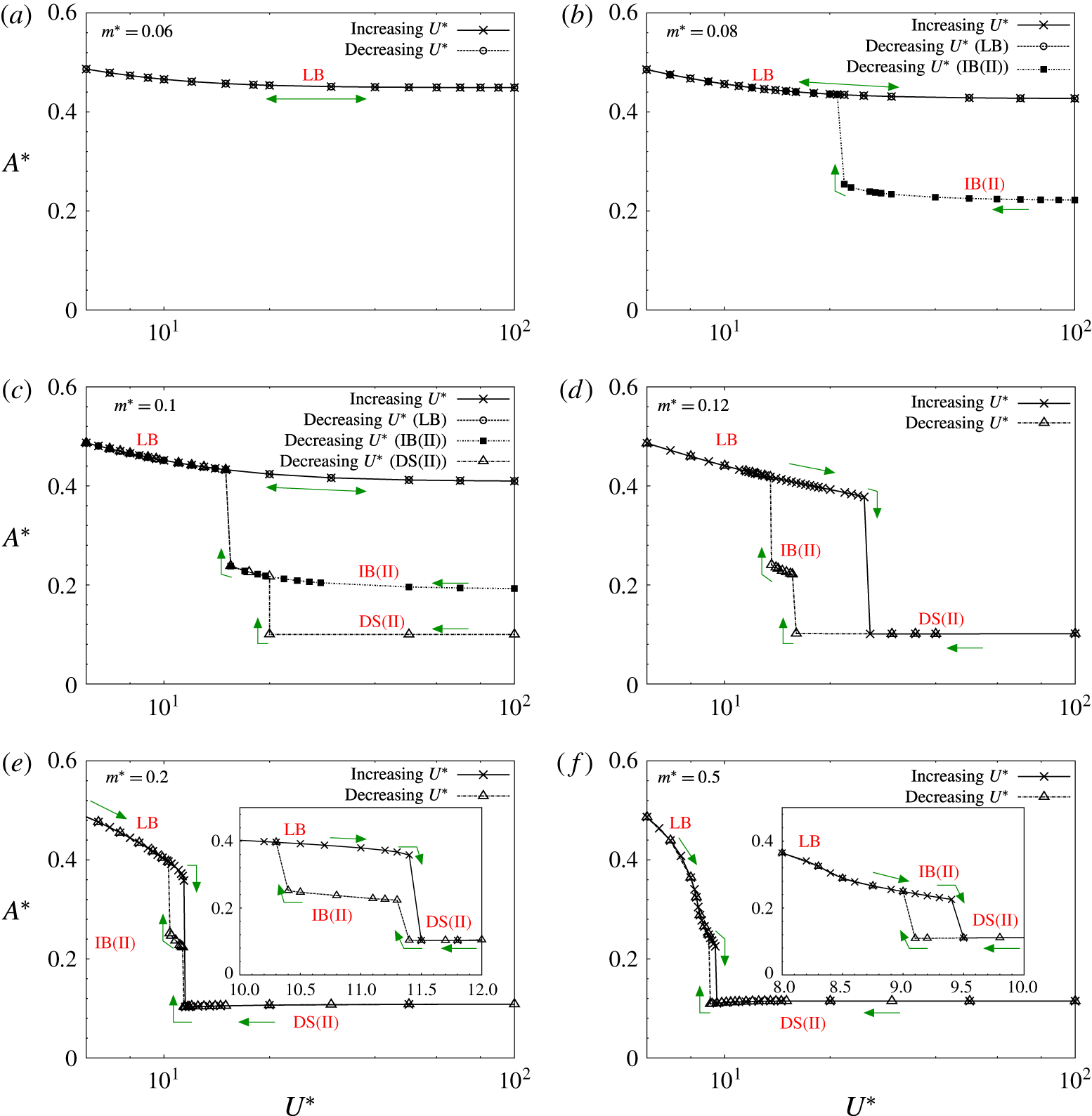
 $Re=150$
flow past a freely vibrating cylinder in presence of spring: hysteresis in the response of the cylinder for (a)
 $m^{\ast }=0.06$
, (b)
 $m^{\ast }=0.08$
, (c)
 $m^{\ast }=0.1$
, (d)
 $m^{\ast }=0.12$
, (e)
 $m^{\ast }=0.2$
and (f)
 $m^{\ast }=0.5$
.

Figure 13 shows that for
 $Re=150$
, the fluid–structure system at
 $U^{\ast }=\infty$
is associated with multiple states for a certain range of
 $m^{\ast }$
. The system may realize one of these states depending on the initial conditions. In fact, three states, corresponding to the three regimes: LB, IB(II) or DS(II), are possible when the mass ratio is in the range
 $0.09\leqslant m^{\ast }\leqslant 0.1$
. The range of
 $m^{\ast }$
, associated with multiple states, is highlighted in figure 13 via shading. The possibility of multiple states at
 $U^{\ast }=\infty$
suggests that hysteresis, with respect to decreasing and increasing
 $U^{\ast }$
should exist for this range of
 $m^{\ast }$
. It is expected that the hysteresis loop for these cases may exist from a finite
 $U^{\ast }$
to
 $U^{\ast }=\infty$
. We refer to this phenomenon as hysteresis forever. It is discussed in detail in the next subsection.
7.2 Hysteresis for finite
$U^{\ast }$

Results from the previous section show that the fluid–structure system, at
 $U^{\ast }=\infty$
, is associated with multiple states for a certain range of
 $m^{\ast }$
. As the response of the cylinder at large
 $U^{\ast }$
(
 ${\sim}100$
) is very similar to that at
 $U^{\ast }=\infty$
, it is expected that multiple solutions exist for large
 $U^{\ast }$
as well. It is, therefore, reasonable to expect hysteretic response with respect to the variation of
 $U^{\ast }$
. To investigate this, computations are carried out for various
 $m^{\ast }$
at finite reduced speeds via two approaches. In the first approach the reduced velocity is increased in small increments. Computations at each
 $U^{\ast }$
are continued long enough to allow the cylinder response to achieve a fully developed state. This solution is used as an initial condition for the incremented value of
 $U^{\ast }$
. We refer to this approach as the increasing
 $U^{\ast }$
approach. For each
 $m^{\ast }$
, the computations begin with a
 $U^{\ast }$
value corresponding to
 $U_{\{C_{EA}=0\}}^{\ast }$
. The response for this
 $U^{\ast }$
lies on the lower branch and the computations are initiated with the
 $Re=150$
steady flow past a stationary cylinder (figure 5
a). In the second approach, the solution for
 $U^{\ast }=\infty$
is used as an initial condition for simulation at
 $U^{\ast }=100$
. The reduced speed is then decreased in small decrements from
 $U^{\ast }=100$
up to
 $U_{\{C_{EA}=0\}}^{\ast }$
. We refer to this approach as the decreasing
 $U^{\ast }$
approach. For the
 $m^{\ast }$
which are associated with multiple states for
 $U^{\ast }=\infty$
(as shown by the shaded region in figure 13), the decreasing
 $U^{\ast }$
approach is undertaken for each state. For clarity, depending on the response branch that the state belongs to, these approaches are referred to as the decreasing
 $U^{\ast }$
(LB), decreasing
 $U^{\ast }$
(IB(II)) and decreasing
 $U^{\ast }$
(DS(II)) approach.
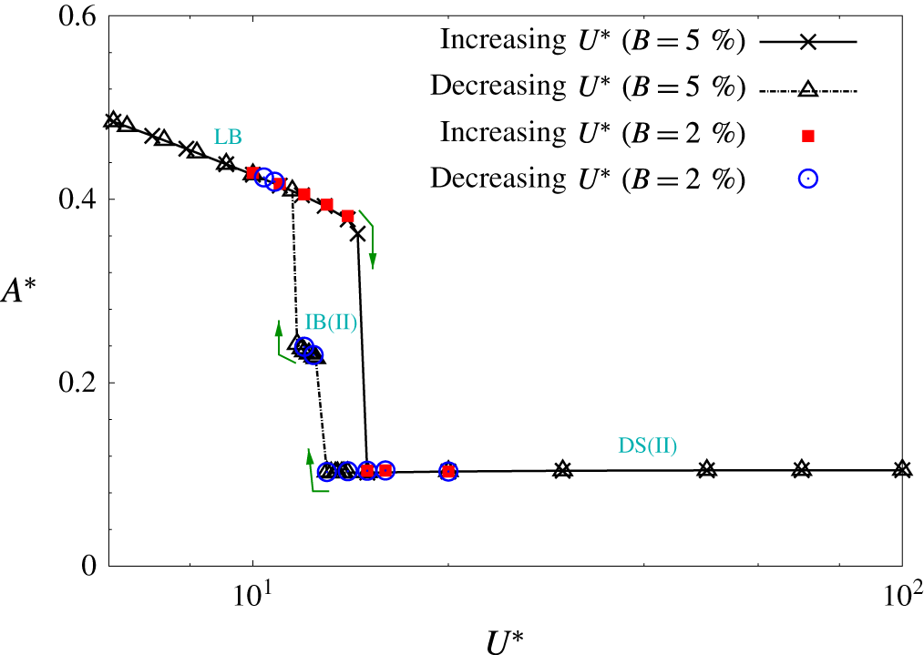
Figure 14 shows the response curves for various
 $m^{\ast }$
obtained via the different approaches. For
 $m^{\ast }=0.06$
, the fluid–structure system has only one response at
 $U^{\ast }=\infty$
and it belongs to the lower branch. In this situation, both the increasing and decreasing
 $U^{\ast }$
approach result in the lower branch solution. For
 $m^{\ast }=0.08$
, solutions obtained via increasing
 $U^{\ast }$
approach remain on LB. With the decreasing
 $U^{\ast }$
approach, two different response curves are obtained corresponding to the two solutions at
 $U^{\ast }=\infty$
. The decreasing
 $U^{\ast }$
(LB) approach results in the same response curve as the increasing
 $U^{\ast }$
approach. On the other hand, with the decreasing
 $U^{\ast }$
(IB(II)) approach the response continues on IB(II) up to
 $U^{\ast }=22.0$
. With further decrease in
 $U^{\ast }$
, it jumps to LB. For
 $m^{\ast }=0.1$
, the increasing
 $U^{\ast }$
and decreasing
 $U^{\ast }$
(LB) approach result in the lower branch response. With the decreasing
 $U^{\ast }$
(IB(II)) approach, the solution remains on IB(II) up to
 $U^{\ast }=20$
and then jumps to LB. On the other hand, with the decreasing
 $U^{\ast }$
(DS(II)) approach, the fluid–structure is desynchronized up to
 $U^{\ast }=16.0$
. With further reduction in
 $U^{\ast }$
, the response first jumps to IB(II) and then to LB. For
 $m^{\ast }>0.1$
, depending on
 $m^{\ast }$
, the response for increasing
 $U^{\ast }$
approach may either transit directly from LB to regime DS(II), or it may first transit from LB to IB(II) and then to DS(II). Similarly, with the decreasing
 $U^{\ast }$
approach there may be a direct transition from DS(II) to LB or a two staged transition from DS(II) to IB(II) and then to LB. The reduced speed at which the transitions occur for the two approaches are different and the two response curves form a hysteresis loop. This regime of hysteresis has been referred to as secondary hysteresis in some of the earlier studies (Prasanth & Mittal Reference Prasanth and Mittal2008; Navrose et al.
Reference Yogeswaran, Sen and Mittal2014).
We define the loop width, of the secondary hysteresis, in terms of
 $U^{\ast }$
. It is the range of
 $U^{\ast }$
where, the increasing
 $U^{\ast }$
approach leads to a response on LB, while the decreasing
 $U^{\ast }$
approach results to a response on either the IB(II) or DS(II). How does the loop width, of the secondary hysteresis, vary with
 $m^{\ast }$
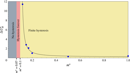
? Figure 15 shows the variation of the width of secondary hysteresis regime (
 $\unicode[STIX]{x0394}U_{H}^{\ast }$
) with mass ratio for
 $Re=150$
.
 $\unicode[STIX]{x0394}U_{H}^{\ast }$
increases with decrease in mass ratio up to
 $m^{\ast }=0.1$
. For
 $0.07\leqslant m^{\ast }\leqslant 0.10$
the system exhibits hysteresis forever wherein the hysteresis regime continues up to
 $U^{\ast }=\infty$
. The occurrence of this phenomenon can be attributed to the existence of multiple states at
 $U^{\ast }=\infty$
(figure 13). For
 $m^{\ast }<0.07$
, the response stays on LB for all
 $U^{\ast }>U_{\{C_{EA}=0\}}^{\ast }$
: lock-in forever. Therefore, the secondary hysteresis does not occur for
 $m^{\ast }<0.07$
.
 $Re=150$
flow past a freely vibrating cylinder: variation of the width of secondary hysteresis regime with mass ratio. The curve is generated from least squares interpolation that utilizes the data points shown as solid circles. For
 $m^{\ast }>0.1$
, hysteresis occurs for finite range of
 $U^{\ast }$
. For
 $0.07\leqslant m^{\ast }\leqslant 0.1$
, the regime of hysteresis continues up to
 $U^{\ast }=\infty$
. For
 $m^{\ast }<0.07$
, no hysteresis is observed in the response of the cylinder.

Flow past a freely vibrating cylinder in the absence of springs: regime of synchronized and desynchronized oscillations on
 $Re{-}m^{\ast }$
plane. The data for high-
 $Re$
regime are taken from Morse & Williamson (Reference Morse and Williamson2009a
) and are shown via hollow squares. The data points for Ryan et al. are shown using solid and hollow triangles. The data points from the present study are shown as filled circles.
 $Re_{j}$
is marked on the
 $Re$
-axis via an arrow.

8 The
$Re{-}m^{\ast }$
map

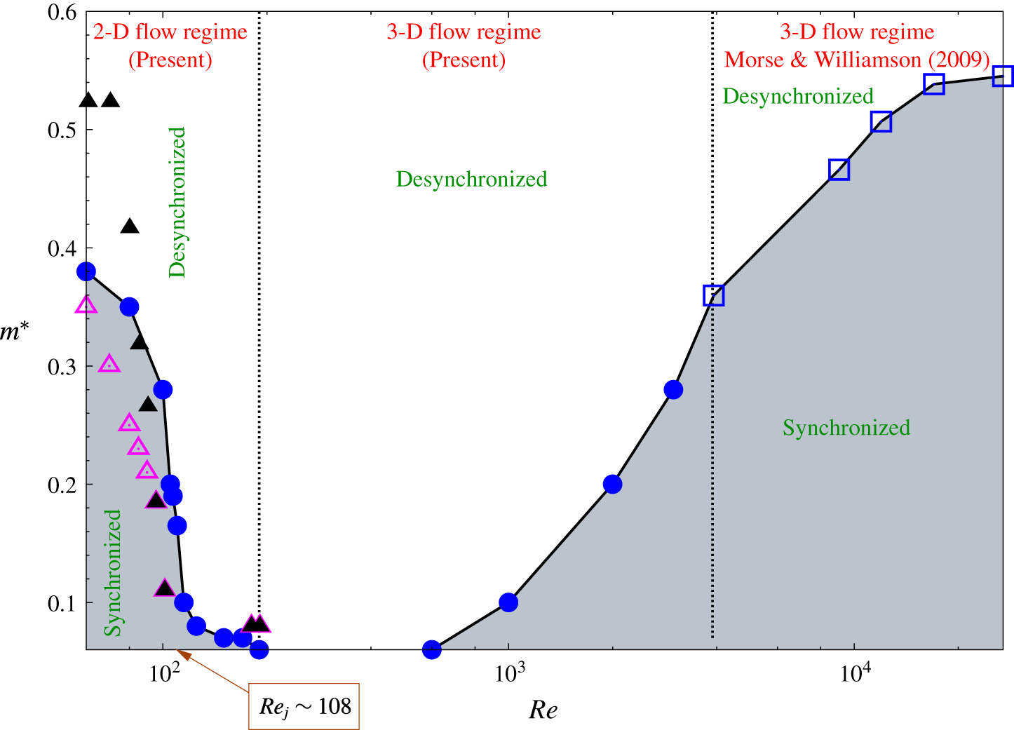
Figure 16 shows a map of synchronized and desynchronized oscillations for
 $U^{\ast }=\infty$
on the
 $Re{-}m^{\ast }$
plane. It addresses the last of the four questions posed in § 4. For
 $Re\leqslant Re_{j}$
, the definition of
 $m_{crit}^{\ast }$
proposed by Ryan et al. (Reference Ryan, Thompson and Hourigan2005) has been utilized. Also shown in figure 16 are the results for high-
 $Re$
regime from Morse & Williamson (Reference Morse and Williamson2009a
). For large
 $Re$
,
 $m_{crit}^{\ast }$
increases with
 $Re$
and saturates beyond
 $Re=10\,000$
to
 ${\sim}0.54$
. In the 2-D flow regime,
 $m_{crit}^{\ast }$
decreases with increase in
 $Re$
. The value of
 $m_{crit}^{\ast }$
decreases from
 $0.38$
for
 $Re=60$
to
 $0.11$
for
 $Re=190$
. Ryan et al. (Reference Ryan, Thompson and Hourigan2005) presented a plot showing the variation of
 $m_{crit}^{\ast }$
with
 $Re$
in viscous (
 $40\leqslant Re\leqslant 95$
) and higher
 $Re$
region (
 $180\leqslant Re\leqslant 200$
). Their results are shown using solid triangle in figure 16. The results from present computation are in reasonable agreement with those from Ryan et al. (Reference Ryan, Thompson and Hourigan2005) in the higher
 $Re$
region where the response jumps sharply as
 $m^{\ast }$
is reduced to a value below the critical mass ratio. However, significant differences are observed in the viscous region where the amplitude of cylinder oscillation increases smoothly with decrease in
 $m^{\ast }$
. To investigate this difference, we utilize the response curves presented by of Ryan et al. (Reference Ryan, Thompson and Hourigan2005) for various
 $m^{\ast }$
to estimate
 $m_{crit}^{\ast }$
using their criterion to determine critical mass ratio for
 $Re\leqslant Re_{j}$
. We found that the
 $m_{crit}^{\ast }$
value, estimated in this manner, is different from the
 $m_{crit}^{\ast }$
data explicitly presented in their paper. These estimates of
 $m_{crit}^{\ast }$
are shown in figure 16 by hollow triangles. The variation of
 $m_{crit}^{\ast }$
so obtained is somewhat closer to the results from present computation. We note that the value of
 $m_{crit}^{\ast }$
estimated using the criterion of frequency minimum depends strongly on the density of the data points near the turning point. Therefore, the difference in
 $m_{crit}^{\ast }$
between the present study and Ryan et al. (Reference Ryan, Thompson and Hourigan2005) may be attributed to difference in the number of data points used to estimate
 $m_{crit}^{\ast }$
. The present work utilizes more data points as compared to the study of Ryan et al. (Reference Ryan, Thompson and Hourigan2005).
To populate the
 $m^{\ast }{-}Re$
plot with more points, we carried out a few simulations beyond the laminar regime. Since the flow is expected to be three-dimensional (3-D) in this regime (Williamson & Govardhan Reference Williamson and Govardhan2004), the computations are carried out in a 3-D domain. The finite element mesh is generated by stacking several slices of the 2-D mesh along the span of the cylinder. The details of the mesh along with its convergence study can be found in our earlier article (Navrose & Mittal Reference Mittal2013). It is observed that for
 $190<Re<1000$
, the fluid–structure system at
 $U^{\ast }=\infty$
is in a desynchronized state even for
 $m^{\ast }$
as low as
 $0.06$
. In this flow regime the critical mass is expected to be less than
 $0.06$
. Because of the enormous computational effort required for the system to achieve a fully developed state at such low values of mass ratio, we have restricted our
 $3D$
computations to
 $m^{\ast }\geqslant 0.06$
. For
 $1000\leqslant Re\leqslant 4000$
,
 $m_{crit}^{\ast }$
increases with
 $Re$
. The trend in in good agreement with that reported by Morse & Williamson (Reference Morse and Williamson2009a
) in the high-
 $Re$
regime.
9 Conclusions
Free vibration of a circular cylinder placed in a uniform flow has been investigated for various mass ratios (
 $0.05\leqslant m^{\ast }\leqslant 10.0$
). In particular, we have explored the existence of critical mass ratio (
 $m_{crit}^{\ast }$
) in the 2-D flow regime. Earlier studies at large
 $Re$
have shown that the width of the lock-in regime increases with decrease in
 $m^{\ast }$
, and below
 $m_{crit}^{\ast }$
, the lock-in regime continues up to infinite reduced velocity (resonance forever). The variation of amplitude of cylinder oscillation at
 $U^{\ast }=\infty$
(
 $A_{\infty }^{\ast }$
) with
 $m^{\ast }$
exhibits a sharp jump below
 $m_{crit}^{\ast }$
signifying the transition from desynchronized state to upper branch of lock-in response. The present computations show that in the 2-D flow regime, the jump in
 $A_{\infty }^{\ast }$
occurs only above a particular
 $Re$
, denoted by
 $Re_{j}$
. For
 $Re<Re_{j}$
,
 $A_{\infty }^{\ast }$
increases smoothly with decrease in
 $m^{\ast }$
with no discernible jump. The value of
 $Re_{j}$
is estimated to lie between
 $107$
and
 $110$
.
Based on the results of the computations at
 $U^{\ast }=\infty$
, four questions were posed that served as motivation for the present work. These are addressed below.
Why is the variation of
 $A_{\infty }^{\ast }$
with
 $m^{\ast }$
associated with jump(s) for
 $Re\geqslant Re_{j}$
, while it is smooth for
 $Re<Re_{j}$
?
The reason is attributed to the change in the nature of transition between the lock-in and desynchronized state towards the higher-
 $U^{\ast }$
end of the lock-in regime.
 $Re\geqslant Re_{j}$
: the transition between lock-in and DS(II) regime occurs with a jump in the response of the cylinder. While the amplitude of cylinder oscillation in regime DS(II) remains nearly constant with
 $m^{\ast }$
, it jumps to relatively large values below
 $m_{crit}^{\ast }$
. For higher
 $Re$
(e.g.
 $Re=150$
), resonance forever may be associated with different branches of lock-in depending on
 $m^{\ast }$
. For example, for
 $(Re,m^{\ast })=(100,0.06)$
resonance forever occurs on LB while for
 $(Re,m^{\ast })=(100,0.08)$
it occurs on IB(II). The transition between the two branches is associated with a sharp change in the amplitude and frequency of cylinder oscillation. In these situations, therefore, the response at large
 $U^{\ast }$
exhibit an additional jump as the mass ratio is reduced further below
 $m_{crit}^{\ast }$
.
 $Re<Re_{j}$
: the transition between lock-in and desynchronized state is smooth. As such, there is no demarcation between the two regimes via a jump in the response of the cylinder. The response for large-
 $U^{\ast }$
increases smoothly with decrease in
 $m^{\ast }$
.
Is the response of the cylinder at
 $U^{\ast }=\infty$
related to that at finite
 $U^{\ast }$
? In particular, can the response at finite
 $U^{\ast }$
be used to estimate that at
 $U^{\ast }=\infty$
?
The dynamics of the fluid–structure system for
 $U^{\ast }=\infty$
is found to satisfy
 $m^{\ast }=[-C_{EA}]$
. Using this equation and the collapsed data curves obtained from finite
 $U^{\ast }$
computation, the response of the cylinder for
 $U^{\ast }=\infty$
is estimated for various
 $m^{\ast }$
. The estimated response is found to be in excellent agreement with the response obtained via direct time integration of the equations at
 $U^{\ast }=\infty$
. Unlike at large-
 $Re$
, the collapsed curves depend on
 $Re$
in the laminar regime.
Variation of
 $A_{\infty }^{\ast }$
with
 $m^{\ast }$
is devoid of jump for
 $Re<Re_{j}$
. Is it possible to identify an alternate criterion to define
 $m_{crit}^{\ast }$
for
 $Re<Re_{j}$
?
For
 $Re<Re_{j}$
, the criterion of
 $m_{crit}^{\ast }$
proposed by Ryan et al. (Reference Ryan, Thompson and Hourigan2005) is used:
 $m_{crit}^{\ast }$
is the mass ratio for which
 $(f_{v_{o}}/f)$
at
 $U^{\ast }=\infty$
achieves the largest value.
 $f_{v_{o}}$
is the vortex shedding frequency associated with the flow past a stationary cylinder at a given
 $Re$
and
 $f$
is the frequency of cylinder oscillation. This criterion is found to be consistent with the conventional definition of
 $m_{crit}^{\ast }$
that is based on the jump in
 $A_{\infty }^{\ast }$
for
 $Re\geqslant Re_{j}$
.
How does
 $m_{crit}^{\ast }$
vary with
 $Re$
, specifically in the low-
 $Re$
regime?
The value of
 $m_{crit}^{\ast }$
decreases with increase in
 $Re$
for
 $Re\leqslant 190$
. For
 $190<Re<600$
, the response of the cylinder at
 $U^{\ast }=\infty$
remains desynchronized up to the lowest value of
 $m^{\ast }$
that has been considered in the present work. Possibly, the value of critical mass ratio is lower than
 $0.05$
in this flow regime. For
 $Re\geqslant 600$
,
 $m_{crit}^{\ast }$
increases with
 $Re$
. The trend matches with the variation of
 $m_{crit}^{\ast }$
in the high-
 $Re$
regime that was reported by Morse & Williamson (Reference Morse and Williamson2009a
). The present work brings out several differences in the response of the fluid–structure system at
 $U^{\ast }=\infty$
between high- and low-
 $Re$
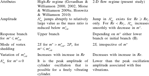
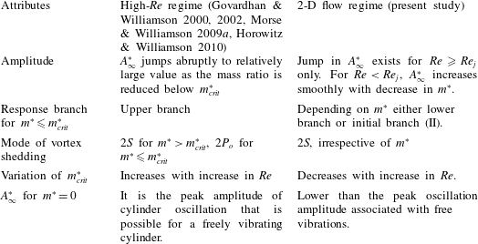
regime. These are listed in table 2.
Difference in the characteristics of the fluid structure system at
 $U^{\ast }=\infty$
between the high-
 $Re$
and 2-D flow regime.
The possibility of multiple response states of the fluid–structure system at
 $U^{\ast }=\infty$
is explored by carrying out computations with different approaches with respect to the initial condition. It is found that only one response state exists for each
 $m^{\ast }$
, for
 $Re<Re_{j}$
. However, two or more response states may exist for
 $Re\geqslant Re_{j}$
for a certain range of
 $m^{\ast }$
. Detailed computations have been carried out for
 $Re=150$
to reveal the existence of multiple states for various
 $m^{\ast }$
. These could lie on lower branch, initial branch(II) or in the desynchronization region (II). Possibly, this is the first time that multiple states have been found for the fluid–structure system at
 $U^{\ast }=\infty$
. The existence of these states lead to an interesting phenomenon: hysteresis forever. It is found, via finite
 $U^{\ast }$
computations, that the cylinder response can be hysteretic in the sense that the increasing
 $U^{\ast }$
and decreasing
 $U^{\ast }$
approaches could lead to different response for the same
 $U^{\ast }$
. The dependence of the width of the hysteresis loop on
 $m^{\ast }$
has been studied for
 $Re=150$
. No hysteresis exists for
 $m^{\ast }<0.07$
. However, hysteresis extends all the way up to
 $U^{\ast }=\infty$
for
 $0.07\leqslant m^{\ast }\leqslant 0.10$
. This is referred to as hysteresis forever. The width of the hysteresis loop decreases with increase in
 $m^{\ast }$
for
 $m^{\ast }>0.1$
. Although it has not been explored, we suspect that multiple states also exist in the high-
 $Re$
regime for certain range of
 $m^{\ast }$
at
 $U^{\ast }=\infty$
. In that case, hysteresis forever might exist for high-
 $Re$
flows as well. The existence of multiple states at
 $U^{\ast }=\infty$
pose a slight ambiguity in the definition of
 $m_{crit}^{\ast }$
. In this work, we have determined the critical mass ratio from the decreasing
 $m^{\ast }$
approach following the work of Govardhan & Williamson (Reference Govardhan and Williamson2000).
Acknowledgements
The authors are grateful to Dr T. K. Prasanth and Mr R. Roy for their help in carrying out some computations. We acknowledge the use of computational resources at High Performance Computing facility, Computer Center, Indian Institute of Technology Kanpur that has been set up with assistance from Department of Science and Technology (DST), India. We are also grateful to Dr D. Philip, Department of Industrial and Management Engineering, IIT Kanpur, for providing access to his computational resources.
Appendix A. Effect of blockage
The effect of blockage on the computations for a freely vibrating cylinder in the laminar flow regime was investigated by Prasanth et al. (Reference Prasanth, Premchandran and Mittal2011). Their study focused on the response of the cylinder during the primary hysteresis that may occur at the onset of synchronization at relatively low
 $U^{\ast }$
. They found that for
 $m^{\ast }<10.11$
, the primary hysteresis depends very significantly on the blockage; it exists for relatively large blockage and disappears when the blockage is smaller than a certain threshold. The focus in the present study is on the critical mass phenomenon which primarily depends on the cylinder response for large
 $U^{\ast }$
. In fact, for
 $Re>Re_{j}$
, large amplitude oscillation of the cylinder may continue up to
 $U^{\ast }=\infty$
. The computations in the present work are carried out for
 $0.05\leqslant m^{\ast }\leqslant 10.0$
using a domain corresponding to
 $5\,\%$
blockage. It is found that although this value of blockage affects the regime of primary hysteresis, the cylinder response towards the end of the synchronization regime is unaffected by this value of blockage. To demonstrate that the blockage in the present work does not significantly affect the results of interest, we compare the response of the cylinder at
 $U^{\ast }=\infty$
for two values of blockage:
 $B=2\,\%$
and
 $5\,\%$
. The regime of secondary hysteresis is also compared for the two blockages. Figures 17(a) and 17(b) show the variation of
 $A_{\infty }^{\ast }$
with
 $m^{\ast }$
for
 $Re=150$
and
 $100$
, respectively. The data points for
 $B=5\,\%$
are shown as hollow squares and that for
 $B=2\,\%$
are shown as filled squares. It is observed that the response is in excellent agreement for the two values of
 $B$
. Figure 18 shows the amplitude response of the cylinder for
 $m^{\ast }=0.15$
computed via increasing
 $U^{\ast }$
and decreasing
 $U^{\ast }$
approach. Excellent agreement is observed between
 $B=5\,\%$
and
 $2\,\%$
. In view of the relative insensitiveness of the results of simulations at large
 $U^{\ast }$
to reducing blockage below
 $5\,\%$
, all the computations in the present work are carried out with
 $B=5\,\%$
.
Flow past a freely vibrating cylinder: effect of blockage ratio on computations carried out at
 $U^{\ast }=\infty$
for (a)
 $Re=150$
and (b)
 $Re=100$
.

 $(Re,m^{\ast })=(150,0.15)$
flow past a freely vibrating cylinder: effect of blockage ratio on the response of the cylinder near the higher-
 $U^{\ast }$
end of the lock-in regime.

Appendix B. The interesting case of
$C_{EA}=0$

The transverse displacement and lift coefficient associated with free vibrations can be represented by the following equations:
 $$\begin{eqnarray}\displaystyle y(t)=A\sin (2\unicode[STIX]{x03C0}ft),\quad F_{y}(t)=F_{o}\sin (2\unicode[STIX]{x03C0}ft+\unicode[STIX]{x1D719}). & & \displaystyle\end{eqnarray}$$
Here,
 $A$
and
 $F_{o}$
are the amplitude of cylinder oscillation and lift force, respectively. The frequency of cylinder oscillation is denoted by
 $f$
. The lift force lags the cylinder displacement by phase angle
 $\unicode[STIX]{x1D719}$
. In general, the sinusoidal variation of displacement and lift force, as given by (B 1), is an excellent representation for a freely vibrating circular cylinder and has been used in several earlier studies (Hover et al.
Reference Hover, Techet and Triantafyllou1998; Khalak & Williamson Reference Khalak and Williamson1999; Govardhan & Williamson Reference Govardhan and Williamson2000; Leontini et al.
Reference Leontini, Stewart, Thompson and Hourigan2005; Morse & Williamson Reference Morse and Williamson2009b
). In certain flow regimes, however, the lift force may have significant contribution from higher harmonics despite the cylinder displacement being nearly sinusoidal (Prasanth & Mittal Reference Prasanth and Mittal2008). In such cases,
 $F_{o}$
is the component of force that varies at fundamental frequency.
Substituting (B 1) in (2.1), and assuming the structural damping to be zero, we obtain:
 $$\begin{eqnarray}-4\unicode[STIX]{x03C0}^{2}mAf^{2}\sin (2\unicode[STIX]{x03C0}ft)+kAsin(2\unicode[STIX]{x03C0}ft)=F_{o}\sin (2\unicode[STIX]{x03C0}ft)\cos (\unicode[STIX]{x1D719})+F_{o}\cos (2\unicode[STIX]{x03C0}ft)\sin (\unicode[STIX]{x1D719}).\end{eqnarray}$$
For (B 2) to hold at all
 $t$
, the following must be satisfied,
 $$\begin{eqnarray}\displaystyle & \displaystyle F_{o}\sin (\unicode[STIX]{x1D719})=0, & \displaystyle\end{eqnarray}$$
 $$\begin{eqnarray}\displaystyle & \displaystyle -4\unicode[STIX]{x03C0}^{2}mAf^{2}+kA=F_{o}\cos (\unicode[STIX]{x1D719}). & \displaystyle\end{eqnarray}$$
These relations are similar to the amplitude and frequency equations proposed by Govardhan & Williamson (Reference Govardhan and Williamson2000). Here, they have been derived for zero structural damping. Equation (B 3) suggests that the phase angle between cylinder displacement and lift force can either be
 $0^{\circ }$
or
 $180^{\circ }$
. The same criteria can also be derived from the balance between the energy transfer from the fluid to structure and the energy dissipated by structural damping. Equation (B 4) can be cast in terms of non-dimensional parameters as
 $$\begin{eqnarray}\frac{f_{v_{o}}}{f}=U^{\ast }St_{o}\sqrt{\frac{m^{\ast }+C_{EA}}{m^{\ast }}},\end{eqnarray}$$
where,
 $$\begin{eqnarray}C_{EA}=\frac{1}{2\unicode[STIX]{x03C0}^{3}}\frac{C_{L_{o}}\cos (\unicode[STIX]{x1D719})}{A^{\ast }St_{o}^{2}}\left(\frac{f_{v_{o}}}{f}\right)^{2}.\end{eqnarray}$$
The quantity represented by
 $C_{EA}$
appears along with the mass ratio in (B 5) and is referred to as the effective added mass coefficient (Khalak & Williamson Reference Khalak and Williamson1999). Physically,
 $C_{EA}$
may be interpreted as an additional mass due to the component of transverse force that is in phase with the body acceleration.
Each point on the collapsed
 $C_{EA}$
curve (CCC) is associated with combinations of
 $\{U^{\ast },m^{\ast }\}$
that satisfy the frequency equation given by (B 5). An example of CCC for
 $Re=100$
is shown in figure 10(b). For
 $C_{EA}=0$
, equation (B 5) becomes independent of
 $m^{\ast }$
and can be written as,
 $$\begin{eqnarray}U_{\{C_{EA}=0\}}^{\ast }=\frac{1}{St_{o}}\left(\frac{f_{v_{o}}}{f}\right)_{\{C_{EA}=0\}}.\end{eqnarray}$$
As seen from figures 10 and 11,
 $C_{EA}=0$
is associated with a certain fixed value of
 $f_{v_{o}}/f$
. Therefore, it can be deduced from (B 7) that for a given
 $Re$
,
 $C_{EA}=0$
occurs at a specific
 $U^{\ast }$
, irrespective of
 $m^{\ast }$
. Further, as seen from the CAC, the amplitude of cylinder oscillation for
 $C_{EA}=0$
also does not vary with
 $m^{\ast }$
. The
 $U^{\ast }$
for
 $C_{EA}=0$
is
 $6.6$
for
 $Re=100$
and
 $5.9$
for
 $Re=150$
. It is seen from figure 5(a,b) that at these
 $U^{\ast }$
, for the respective
 $Re$
,
 $A^{\ast }$
is indeed independent of
 $m^{\ast }$
. Figure 5(a,b) helps us answer another interesting question. At a given
 $Re$
and
 $U^{\ast }$
, does the amplitude of cylinder response increase or decrease with decrease in
 $m^{\ast }$
? These figures show that for
 $U^{\ast }<U_{\{C_{EA}=0\}}^{\ast }$
,
 $A^{\ast }$
decreases with decrease in
 $m^{\ast }$
in the lock-in regime. The trend is opposite for
 $U^{\ast }>U_{\{C_{EA}=0\}}^{\ast }$
.