Introduction
In modern wireless communication systems such as 5G technology, two things are very important: (i) high data rate without enhancing the power level and (ii) a compact system with low insertion loss [Reference Kornprobst, Wang, Hamberger and Eibert1]. In order to attain these features, the concept of multiple-input multiple-output (MIMO) antennas comes into forefront, which provides a very high data rate. Even at the millimeter (mm)-wave range, this system becomes more efficient because of its subsequent bandwidth. It is due to the attainment of a higher data rate with the assistance of increment in bandwidth and improvement in the signal-to-noise ratio. Filtering antennas are used to reduce the size of the antenna while maintaining a low insertion loss [Reference Liu, Leung, Ren and Sun2]. This study has merged two concepts, namely MIMO and filtering response. This idea is being suggested for the first time in the literature, and it results in a highly efficient antenna for 5G communication systems. Due to its minimal dielectric loss even at extremely high frequencies, dielectric resonator antennas (DRAs) are commonly employed in mm-wave applications. That is why it has high efficiency of radiation at mm-wave frequencies. Shen and his research team established the radiating capacity of the dielectric antenna for the first time in 1983 [Reference Long, McAllister and Shen3].
In the case of mm-wave MIMO antenna design, researchers have focused on the high isolation between the antenna ports for obtaining a good diversity value. One of the most generalized techniques for obtaining high isolation is to create orthogonal modes between different ports [Reference Sharma, Sarkar, Biswas and Akhtar4, Reference Sharma and Biswas5]. Zhang et al. proposed the concept of parasitic metallic strips among the different ports for enhancing the isolation value [Reference Zhang, Deng, Li, Sun and Guo6]. Metasurface shield [Reference Sufian, Hussain, Askari, Park, Shin and Kim7], as well as frequency selective surface wall [Reference Thummaluru, Kumar and Chaudhary8] inserted in between the ceramic material, provides a better isolation value. These techniques provide a better diversity value through S-parameters. In the case of MIMO antennas, diversity parameters must be calculated through far-field parameters. Beam tilting with the assistance of partially reflecting surfaces [Reference Das, Sharma, Gangwar and Sharawi9] and radiator location in a different direction [Reference Das, Sharma, Gangwar and Sharawi10] provides the efficient value of diversity parameter through far-field parameters.
Additionally, other approaches such as filter synthesis are accessible in the literature for prototyping filtering antennas. The antenna output is coupled to the filter input in this approach. However, this strategy does not result in a reduction in the size of the system [Reference Yusuf, Cheng and Gong11, Reference Mao, Gao, Wang, Sanz-Izquierdo, Wang, Qin, Chu, Li, Wei and Xu12]. The alternative method for establishing a filtering response is to include parasitic strips or metallic vias into the feeding mechanism of the radiator. The fundamental problem of these systems is that the electromagnetic (EM) energy is trapped in the feed network and cannot be effectively disseminated over the antenna. Rather than changing the feed network, aperture and metallic patches of the antenna provide the filtering response [Reference Hu, Pan, Zhang and Hu13, Reference Hu, Pan, Zhang and Zheng14]. This approach enables both size reduction and harsh band edge selection.
This paper suggests an MIMO antenna based on filtering dielectric resonators. This is the first time that a filtering approach has been used with an MIMO antenna operating at low mm-wave frequencies. With the help of a metallic plate sandwiched between the ports, the suggested antenna configuration attains a high diversity parameter. The antiparallel orientation of the antenna ports also aids in this endeavor. The field formed within the DRA is equivalent in amplitude and phase to the field outside. It gives the filtering response, i.e. gain suppression of ~15 dB slightly outside the frequency spectrum. The suggested antenna operates between 27.9 and 28.5 GHz and has a >30 dB isolation value. Sections “Antenna design and fabrication” and “Antenna analysis” include both antenna design and analysis. Sections “Experimental outcomes” and “conclusion” summarize the results of the experiments and reach a conclusion.
Antenna design and fabrication
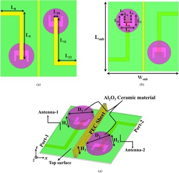
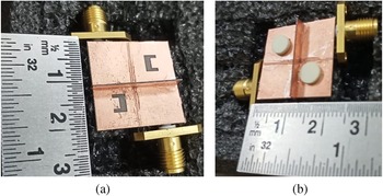
Figure 1 illustrates the geometrical layout of the proposed filtering MIMO antenna. Two cylindrical DRs are fixed on the Rogers RT 5880 substrate (ɛ r = 9.8 and tanδ = 0.002). The size of the substrate is 20 × 20 × 0.254 mm3. Its relative permittivity is 2.2 and tan δ is ~0.0009. Microstrip line fed U-shaped aperture is cut in the ground plane for the excitation of ceramic material. The double-sided Rogers RT 5880 substrate is placed in between two ports for beam tilting. Figure 2 shows the prototype of the proposed MIMO filtering antenna. Table 1 lists the optimized value of different parameters of the proposed antenna.
Geometry of the proposed MIMO filtering antenna: (a) bottom view, (b) top view, and (c) 3D view.

Fabricated MIMO filtering Antenna: (a) top view with aperture without ceramic and (b) side view with ceramic.

Optimized dimensions of the different parameters of the proposed MIMO filtering antenna

Antenna analysis
This section provides a full overview of the design process of the proposed antenna in a step-by-step fashion. The antenna was modeled and analyzed using ANSYS HFSS simulation software.
Accountability of resonance
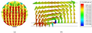
For finding out the accountability of resonance obtained at 28.0 GHz, Fig. 3 displays the |S 11| variation for the proposed MIMO antenna with and without cylindrical ceramic. From Fig. 3, it can be confirmed that the complete operating frequency band for the proposed antenna is due to cylindrical-shaped ceramic. Figure 4 presents the side and top views of the E-field plot on cylindrical ceramic at 28.0 GHz. From Fig. 4, it is confirmed that HEM11δ mode is obtained at 28.0 GHz [Reference Kajfez, Glisson and James15]. The resonance frequency of HEM11δ mode can also be verified by using the following mathematical formula [Reference Mongia and Bhartia16]:

Variation in |S 11| with and without cylindrical ceramic.

E-field plot on cylindrical ceramic at 28.0 GHz: (a) top view and (b) side view.

In equation (1), “ɛ r” denotes the permittivity of cylindrical ceramic and “c” denotes the velocity of light. From equation (1), the resonance frequency is ~27.56 GHz, which is quite close to simulated results.
Step-by-step design process
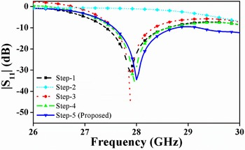
Figure 5 shows the step-by-step development of the proposed aperture for feeding the cylindrical-shaped alumina. Step-1 and step-2 are simply horizontal and vertical apertures coupled ceramic respectively. Step-3 is L-shaped (smaller edge) aperture coupled cylindrical ceramic. Step-4 is L-shaped (larger edge) aperture coupled with cylindrical ceramic. Step-5 shows the proposed asymmetrical U-shaped aperture. Figures 6 and 7 display the |S 11| and realized gain for different steps involved in designing of the proposed aperture. From Figs 6 and 7, some observations are found: (i) horizontal aperture excites the cylindrical ceramic and provides ~5.0 dBi within the operating band; (ii) vertical aperture does not excite the ceramic and gain value is ~−6.0 dBi within the band; (iii) L-shaped aperture with smaller edge provides the resonance at 28.0 GHz, while gain value suddenly decreases at 28.2 GHz; (iv) L-shaped aperture with larger edge provides the resonance at 28.0 GHz, while gain value suddenly decreases at 27.8 GHz; and (v) proposed asymmetrical U-shaped aperture provides resonance at 28.0 GHz and bandpass type gain response is obtained.
Step-by-step design process for the feeding aperture of the proposed radiator.

Reflection coefficient (|S 11|) variation with different steps involved to design the feeding aperture of the proposed radiator.

Realized gain variation with different steps involved to design the feeding aperture of the proposed radiator.

Analysis of filtering response
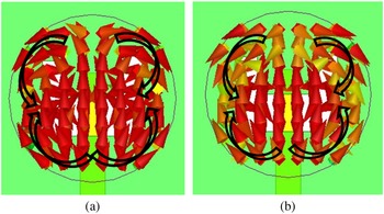
To investigate the radiation nulls at 27.8 and 28.2 GHz, the near field is plotted at these two frequency points. It is shown in Fig. 8. It is observed from Fig. 8 that asymmetrical U-shaped aperture creates two out-of-phase E-field lines at 27.8 and 28.2 GHz respectively. It creates radiation nulls at these two frequency points. The authors have taken advantage of vertical aperture, which provides radiation null in the operating frequency range. So, the vertical aperture with different dimensions is placed at two different positions on the horizontal aperture (asymmetrical U-shaped aperture), which provides a bandpass filtering response.
Plot of E-field lines on cylindrical ceramic material at (a) 27.8 GHz and (b) 28.2 GHz.

Analysis of mutual coupling
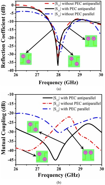
Figures 9(a) and 9(b) illustrate the variation of the reflection coefficient and mutual coupling in three distinct cases: (i) two ports placed parallel; (ii) two ports placed antiparallel; and (iii) two ports placed antiparallel with a Perfect Electric Conductor (PEC) plate between the ports. As illustrated in Fig. 9(a), the reflection coefficient (|S 11|) is nearly identical in all three scenarios. The lowest mutual coupling (<−40 dB) is obtained when the PEC plate is placed in between two anti-parallel ports shown in Fig. 9(b). The anti-parallel placing of ports provides the space diversity as well as placing of the PEC plate in between two ports resists the current flow from one port to another [Reference Dwivedi, Sharma, Singh and Singh17].
(a) Reflection coefficient variation with three different cases. (b) Mutual coupling variation for different configurations.

Correlation between the radiation patterns obtained from different ports should be minimal in the case of an efficient MIMO antenna design [Reference Sharawi18]. This is accomplished by encasing a PEC sheet between two ports. The use of a PEC sheet modifies the wavefront of the EM wave. For understanding the concept of beam tilting, EM wave with wavelength “λ” is strike on PEC at angle “φ”. Because of the phase gradient of the PEC sheet, the beam is slanted by angle “θ”. This can be calculated as follows [Reference Yu, Genevet, Kats, Aieta, Tetienne, Capasso and Gaburro19]:

At the specific frequency, the PEC sheet creates a constant phase gradient. Because of this,

In equations (2) and (3), dϕ/dr denotes the phase gradient. From equations (2) and (3), it can be observed that the tilting angle “θ” directly depends upon “φ”. This striking angle of EM wave (φ) is to be governed by the relative distance between cylindrical ceramic and PEC sheet. Figure 10 illustrates a three-dimensional radiation pattern plot with port-1 and port-2 operating at 28.0 GHz. Between two ports, a PEC plate is inserted. From Fig. 10, it is observed that the presence of a PEC sheet in between two ports tilts the radiation pattern.
3D radiation pattern obtained from two antenna ports in the presence of PEC sheet at 28.0 GHz.

Experimental outcomes
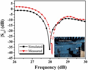
In this section, practical results obtained from the fabricated prototype are discussed and compared with the simulated outcome. Scattering parameters are measured with the assistance of E8363C Keysight-based PNA. Figures 11 and 12 show the measured and simulated |S 11| and |S 12| variation. From Figure 11, it is confirmed that the proposed antenna operates within the frequencies of 27.9 and 28.5 GHz. Similarly, throughout the working frequency range, mutual coupling between two ports is <−30 dB. It is confirmed from Fig. 12. However, shifting is observed in measured results concerning the measured one. It is due to the use of adhesive material as well as connector used [Reference Faiz, Gogosh, Khan and Shafique20]. A shift in measured results is also due to the imperfect soldering of the connectors and the small difference in the value of the relative permittivity/loss tangent of the materials.
Measured and simulated |S 11| variation for the proposed MIMO filtenna.

Measured and simulated |S 12| variation for the proposed MIMO FILTENNA.

Figure 13 presents measured and simulated realized gain variation. Practically, the gain is measured with the help of the two antenna method [Reference Stutzman and Thiele21]. From Fig. 13, it is confirmed that the maximum gain is ~4.5 dBi within the operating frequency band. Bandpass type filtering response is obtained for the proposed antenna. It is also observed from Fig. 13 that there is a change in measured and simulated gain value. It may be fabrication tolerances or imperfect soldering. During measurement, sometimes there is misalignment between reference as well as a testing antenna. It is also a reason for a change in measured results.
Peak gain variation for proposed filtering MIMO antenna.

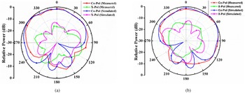
Figure 14 displays the far-field pattern in the YZ plane with port-1 and port-2 at 28.1 GHz. During far-field measurement inside the anechoic chamber, one port is terminated with matched load, while the other port is excited. Radiation pattern is tilted ~−45 and +45° with port-1 and port-2, respectively. The cross-polarization level is also well below (>15 dB) with respect to the co-polarization in the desired direction.
Far-field pattern in the YZ plane at 28.1 GHz: (a) port-1 and (b) port-2.

In the case of MIMO antennas, the most vital diversity parameters are the envelop correlation coefficient (ECC) and diversity gain (DG) [Reference Sharawi22]. There are two methods for determining the ECC and DG: (i) using the S-parameter or (ii) using the far-field parameter [Reference Sharawi22]. Figure 15 shows the ECC and DG with the help of the S-parameter. From Fig. 15, it is observed that the value of ECC and DG is ~0.003 and 9.99 dB in the operating band, which is quite good in comparison with the standard one. Table 2 lists the calculated value of ECC and DG with the help of the far-field parameter. From Table 2, it is observed that the value of ECC is quite low. Similarly, the value of DG is high. It is due to the tilting radiation pattern. As the uncorrelated radiation pattern is obtained from different ports, the value of ECC using far-field becomes quite low and makes the MIMO radiator more efficient [Reference Sharawi18]. Figure 16 shows the variation of another important diversity parameter, i.e. total active reflection coefficient (TARC). It is the reflection coefficient of the complete MIMO antenna [Reference Sharawi22]. As illustrated in Fig. 16, resonant peak and impedance bandwidth of the proposed MIMO antenna remain constant regardless of the feeding phase angle.
ECC and DG variation over the complete frequency range.

Variation of TARC for the proposed MIMO filtering antenna.

Calculated value of ECC and DG using far-field value

The suggested MIMO antenna is compared to other published DR-based MIMO antennas in Table 3. According to Table 3, the suggested antenna possesses both filtering and beam tilting capabilities. This is the key characteristic of the antenna.
Performance comparison of the proposed MIMO antenna with existing DR-based MIMO antenna

Conclusion
This paper describes the design and analysis of a two-port MIMO filtenna operating at low mm-wave frequencies. A ceramic-based radiator has been used to attain excellent antenna properties at low mm-wave frequencies. The proposed antenna works in a frequency range of 27.9–28.5 GHz. Mutual coupling between the two ports also exceeds 30 dB. Two critical aspects distinguish the proposed radiator from others: (i) the asymmetrical U-shaped aperture offers bandpass filtering and compacts the antenna and (ii) the employment of a PEC sheet between the two ports tilts the radiation pattern, which enhances the performance of MIMO antenna. All of these features of the proposed antenna make it suitable for 5G Internet of Things applications.
Data availability statement
Data sharing not applicable – no new data generated.
Acknowledgement
Anand Sharma wishes to acknowledge SERB, New Delhi for providing financial support to conduct this study successfully under the scheme of Startup Grant (SRG) with notification No. SRG/2020/000043 dated 27/10/2020.
Conflict of interest
The author declares no potential conflict of interest.
 Darshika Sharma was born in Jaipur district of Rajasthan in 1999. She has completed her bachelor's in 2021 from the Motilal Nehru National Institute of Technology in Electronics and Communication Engineering. She is working as an associate software engineer in Gartner. Her research interest lies in communication technology and machine learning techniques for image enhancement and medical image processing. She has collaborated actively with researchers in several disciplines of research interest.
 Rishika Katiyar was born in Kanpur district of Uttar Pradesh in 1998. She has completed her graduation in 2021 from the Motilal Nehru National Institute of Technology, Kanpur (U.P.) in Electronics and Communication. She is working as a technology analyst in Deutsche Bank since July 2021. She worked on a project based on “Design and Analysis of Dielectric-Resonator Antennas for 5G Communication” in her final year of engineering. Apart from this, she also worked as Intern for Visa Inc. in summer 2020.
 Dr. Ajay Kumar Dwivedi is an Associate Professor at the Department of Electronics and Communication Engineering at the Nagarjuna College of Engineering and Technology in Bengaluru, India. He received his Ph.D. in Electronics and Communication Engineering from the Indian Institute of Information Technology Allahabad, Prayagraj, Uttar Pradesh, India in 2021. He received his Master of Technology degree in Wireless Communication Engineering from the Sam Higginbottom University of Agriculture, Technology, and Sciences, a Deemed University in Allahabad, Uttar Pradesh, India, in 2015. In 2010, he received his Bachelor of Technology in Electronics and Communication Engineering from Uttar Pradesh Technical University in Lucknow, India. He has published about 50 research papers in international/national journal/conference proceedings as an author or co-author. His research interests include radiofrequency and microwave engineering, microstrip patch antennas, wireless communication, antenna theory, dielectric resonator antennas, MIMO DRAs, and metamaterial-based dielectric resonator antennas.
 Dr. K.N. Nagesh is working as a Professor and Head of the Department in Electronics and Communication Engineering, Nagarjuna College of Engineering & Technology, Bengaluru, India. He has completed his Ph.D. from Jawaharlal Nehru Technological University Anantapur (JNTUA), Anantapur, A.P., India in 2016. In 2007, he received his M.Tech. degree in Digital Electronics and Communication from Nitte Mahalinga Adyanthaya Memorial Institute of Technology (NMAMIT), Mangalore, VTU, Karnataka, India. He has completed his B.E. in Electronics and Communication Engineering from the Siddaganga Institute of Technology (SIT), Tumkur, VTU, Karnataka, India in 2005. He has 15 years of teaching experience for UG and PG students. He has authored or co-authored more than 35 research papers in international journal/conference proceedings. His research interests include wireless communication, communication systems, IoT, and antennas. He is a reviewer of several international journal/conference proceedings.
 Dr. Anand Sharma was born in Agra (U.P.), India, in 1990. He received his B.Tech. in Electronics and Communication Engineering from Uttar Pradesh Technical University, Lucknow, India, in 2012 and his M.Tech. in ECE from the Jaypee University of Engineering and Technology, Guna (M.P.), India. He has completed his Ph.D. from the Department of Electronics Engineering of the Indian Institute of Technology (Indian School of Mines), Dhanbad, India in 2018. He is currently an Assistant Professor in the Department of Electronics and Communication Engineering, Motilal Nehru National Institute of Technology Allahabad, Prayagraj, U.P., India. He has authored or co-authored over 80 research papers in international/national journal/conference proceedings. His research interests include dielectric resonator antennas and microstrip antennas.
 Dr. Pinku Ranjan born in Nalanda (Bihar), India, in 1988. He is working as an Assistant Professor in ABV-IIITM Gwalior, M.P., India. He received his Ph.D. degree from the Indian Institute of Technology (Indian School of Mines), Dhanbad, India in 2017. He received his B.Tech. in Electronics and Communication Engineering from Jawaharlal Nehru Technological University (JNTU), Hyderabad, India in 2010. He has authored or co-authored more than 30 research paper in international/national journal/conference proceedings. He is a reviewer of several international/national journal/conference proceedings such as IEEE Transactions on Image Processing, IEEE Access, AEU: International Journal of Electronics and Communications, Elsevier. His research interests include dielectric resonator antennas, MIMO 5G antennas, monopole antennas, multiband hybrid antennas, circularly polarized antennas, bio-electromagnetics, machine learning, deep learning, IOT devices, and Image processing.