I. INTRODUCTION
Nose-cones of hypersonic vehicles experience temperatures in excess of >2200 °C, and are associated with severe oxidation, extreme heat fluxes, and high mechanical stresses. Such demanding requirements mandate good chemical resistance, and high melting temperatures (>3300 K) toward use as an ultrahigh temperature ceramic (UHTC).Reference Storms1 Among the UHTCs, TaC is an important transition metal mono-carbide, possessing an extremely high melting point of ∼4200 K (Ref. Reference Kim, Gottstein and Grummon2), making its consolidation into useful engineering shapes a major challenge. Since, solid state sintering occurs typically at temperatures >0.5T m, the temperature required for consolidation of TaC exceeds >2500 K under pressureless conditions, whereas under pressure-assisted sintering conditions, i.e., spark plasma sintering (SPS) and hot pressing, sintering temperature can be brought down to as low as 1600 K.Reference Samonov and Petrikina3–Reference Zhang, Hilmas, Fahrenholtz and Deason7 SPS is a relatively novel consolidation method for the synthesis of UHTCs composites, and provide an advantage of short sintering duration even to achieve nearly full densification (∼100%) while showing superior mechanical properties (hardness, elastic modulus, and fracture toughness) than hot pressing.Reference Monteverde8,Reference Zhang, Xu, Du, Liu, Han and Han9 In earlier publications, the unique capability of multistage SPS approach to develop ceramics with uniform and better mechanical properties has already been established.Reference Bajpai, Balani and Basu10,Reference Dubey, Ea, Balani and Basu11 An alternative method to deal with the issue of sinterability and difficulty to reach full densification and the relatively low strength (∼400 MPa) and toughness (∼3.4 MPa m1/2) of TaC materials,Reference Liu, Kan and Zhang4,Reference Hackett, Verhoef, Cutler and Shetty12,Reference Silvestroni, Bellosi, Melandri, Sciti, Liu and Zhang13 secondary agent such as TaB2, B4C, MoSi2, and SiC have been utilized, among which SiC is proved to be one of the best additives.Reference Zhang, Hilmas and Fahrenholtz14–Reference Zhu, Fahrenholtz and Hilmas18 Liu et al. have reinforced 5–40 vol% SiC in TaC and have demonstrated that the addition of 15–20 vol% SiC improves fracture toughness by 200% (∼6.8 MPa m1/2) and increases strength (∼703 MPa) when compared to that of monolithic TaC (280 MPa).Reference Liu, Ye, Zhang and Zhou19 In the recent studies, carbon nanotubes (CNT) and graphene nanoplatelets have also been utilized to improve consolidation and fracture toughness using SPS, and make CNT-reinforced TaC a preferred candidate for aerospace application.Reference Balani, Gonzalez, Agarwal, Hickman, O'Dell and Seal20–Reference Nieto, Lahiri and Agarwal24 On one hand, where the thermal resistance of SiC reinforcement is well established, reinforcement of thermally conductive CNTs [∼3000 W/(m K)]Reference Bakshi, Balani and Agarwal25 may provide enhanced resistance to thermal damage of TaC-composites. It may be noted that Bakshi et al. have utilized 4 wt% CNT in TaC matrix, which roughly corresponds to reinforcement of ∼22 vol% CNTs in TaC matrix.Reference Srinivasa, Musaramthota, Virzi, Keshri, Lahiri, Singh, Seal and Agarwal21 Thus, based on the literature, a synergistic reinforcement of 15 vol% SiC and 15 vol% CNTs in TaC matrix is adopted in the present study. Apart from achieving enhanced densification, the current study focuses on correlating the synergistic role of SiC and CNT reinforcement on the fracture toughness and fracture energy of resulting TaC-based UHTC composites. The thermal residual stresses are well known to affect the macroscopic mechanical behaviors of ceramics and their composites: depending upon the stress state of the constituents (compressive or tensile stresses).Reference Khaleghi, Lin, Meyers and Olevsky5,Reference Chen, Balani and Agarwal26 Therefore, it is of fundamental significance to investigate the contributions of thermal residual stresses on the toughness of TaC based composites. Accordingly, contributions of the interfacial thermal residual stresses, between the matrix and reinforced particles, on affecting the fracture toughness are established using an analytical model.
II. MATERIALS AND METHOD
A. Preparation of composites
Commercial powders of TaC (Inframat Advanced Materials LLC, Manchester, Connecticut, 99.7% pure, particle size < 2 μm), SiC (H.C. Starck, Munich, Germany, 99.9% pure, particle size < 1 μm) with the spherical morphology and multiwalled carbon nanotubes (CNTs, 95% pure, outer diameter of 40 nm, inner diameter of 20 nm, and 1–2 μm long; Nanostructured and Amorphous Materials Inc., Houston, Texas) were used as the starting materials.
TaC (labeled as T, Fig. 1(a)) is blended with: (i) 15 vol% SiC (labeled as T15S), (ii) 15 vol% CNT (labeled as T15C), and (iii) 15 vol% SiC and 15 vol% CNT (labeled as T15S15C, Fig. 1(b)). These mixtures were ultrasonicated in ethanol for 30 min for uniform dispersion, dried for 12 h and sieved (mesh size > 1 μm) to obtain the composite powders. Figures 1(a) and 1(b) show the micrographs of the starting powder compositions in T and T15S15C, along with the pristine CNT powder [Fig. 1(c)]. The uniform distribution of secondary phase particles (SiC as well as CNT) in TaC matrix is attached as supplements S1(a) and S1(b).
SEM micrographs of the starting TaC based composite powders: (a) T, (b) T15S15C, and (c) TEM micrograph of the pristine CNT powder.

B. Spark plasma sintering for processing of TaC–SiC–CNT composites
The blended composite powders were processed via spark plasma sintering (SPS; Dr. Sinter Lab Series, SPS-515S, Tokyo, Japan) at 1850 °C in vacuum (<6 Pa), uniaxial pressure of 40 MPa, soaking time of 5 min, and a heating rate of 150 °C/min. Triple stage sintering was used to provide uniform densification for each composition, which involved temperature cycle holding for 5 min at 1350, 1650, and 1850 °C (as shown in supplement S2). Graphite dies and punches were used for sintering disc-shaped samples of diameter 15 mm and 3 mm thickness. The ram displacement was observed throughout during the SPS sintering cycle to investigate the densification behavior. The final density values were measured using Archimedes principle (water immersion technique).
C. Phase analysis
Phase characterization of SPS processed TaC based composites was carried out using Cu Kα radiation (λ = 1.54 Å) on a X-ray diffractometer (XRD; Bruker AXS, D8 Focus, Karlsruhe, Germany) operated at 25 kV and 15 mA (at scan speed of 0.5 s/step and step size of 0.02°) in the 2θ-range from 20° to 80°. Further, to study the effect of the processing conditions on the structure of CNT, micro-Raman spectroscopy (STR Raman, TE-PMT detector, Princeton Instruments, Tokyo, Japan) was carried out using Nd-YAG green laser (λ = 532 nm) in the backscattered mode.
D. Microstructural characterization
As-sintered TaC/SiC/CNT based composites were ground using SiC papers to remove the graphite layer and then further polished up to 0.1 μm finish using diamond suspension. The fractured surface of the SPS samples were observed using scanning electron microscope (SEM; Carl Zeiss Model EVO 50, Oberkochen, Germany). Transmission electron microscopy (TEM, FEI UT 20, FEI Company, Hillsboro, Oregon), operating at an accelerating voltage of 200 kV, was used to study interfaces and structure of the TaC–SiC–CNT based composites. TEM samples were prepared using 3 mm ultrasonic disc cutter followed by dimpling and precession ion-beam polishing.
E. Mechanical property characterization
1. Hardness and elastic modulus
Hardness and elastic modulus of the TaC-based sintered pellets were measured using instrumented micro indenter (MHT, CSM instruments, Ostfildern, Germany). The load function comprised a loading to 2 N (at ramp rate of 66.67 mN/s and hold at maximum load for 10 s followed by unloading at the same rate) using V-I 51 Vickers' indenter tip. Fracture toughness was calculated by loading of TaC-based sintered pellets at 19.6 N using universal Vickers hardness testing machine (FH-10, Tinius-Olsen Ltd., Horsham, Pennsylvania) with dwell time of 10 s. The generated crack lengths (c) were measured using SEM from the center of indents, and the indentation fracture toughness (K IC) was computed employing Anstis equationReference Anstis, Chantiklul, Lawn and Marshall27
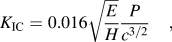 $${K_{{\rm{IC}}}} = 0.016\sqrt {{E \over H}} {P \over {{c^{{3 \mathord{\left/ {\vphantom {3 2}} \right. \kern-\nulldelimiterspace} 2}}}}}\quad ,$$
where E is the elastic modulus, H is hardness, P is load utilized, and c is radial crack length. Student-t-test was performed for an average of ten values for each composite, and the mean indentation fracture toughness value with the confidence level of >95% is reported for TaC based sintered pellets. Although, Vickers' indentation is not very suitable for measuring fracture toughness values when compared with that of single-edge-notched beam (SENB) method,Reference Awaji and Sakaida28,Reference Wang, Padture and Tanaka29 but a similar trend of fracture toughness is reported for samples in the literature.Reference Anstis, Chantiklul, Lawn and Marshall27,Reference Chantikul, Anstis, Lawn and Marshall30 It is to be noted that indentation fracture toughness technique is used only as a “ranking parameter” toward comparing the toughness of TaC based composites.
2. Diametrical compression test
Diametrical compression test was carried out on each material (pellets with diameter 15 mm and thickness 3 mm) using a 100 kN Universal Testing Machine (UTM, Model: BiSS Ltd., Bengaluru, India) at a strain rate of 0.05 mm/min (see Fig. S3). The fracture-strength of the material was calculated using the following formula:Reference Albedah and Benyahia31,Reference Procopio, Zavaliangos and Cunningham32
 $$\sigma = {{2P} \over {\pi Dt}}\quad ,$$
where σ is the fracture tensile strength, P is the maximum load at which the fracture occurs, t is the thickness, and D is the diameter of the sample. Due to limitation of material cost and processing techniques, only two TaC based SPSed samples were tested and their average (obtained within 15% deviation) is reported.
III. RESULTS AND DISCUSSION
A. Densification of TaC–SiC–CNT based composites
The densification of TaC based composites increased from 93% for monolithic TaC to 98% with synergistic reinforcement of both SiC and CNT in TaC matrix (mentioned along with their nomenclature in Table I) under similar SPS processing conditions shown in Fig. 2. During SPS, the recorded punch displacement profile indicates three distinct regions, i.e., (i) initial increasing trend (step I, compaction) corresponding to increasing pressure due to the rearrangement of powder particles, (ii) intermediate decreasing trend (step II) corresponding to thermal expansion, and (iii) final increasing trend (step III, shrinkage) corresponding to final densification stages as shown in Fig. 2. The extent of punch displacement during the step I is minimum in TaC, but the displacement increases with the increasing content of SiC (T15S) and CNT (T15C), and especially T15S15C, which has shown to facilitate the densification even during step I (compare the flat step I for TaC). It may be noted that punch displacement is observed to decrease (or a decrease in densification is observed in step II for T15C and step III for T15S15C), which may be attributed to the thermal expansion of composites at sintering temperature. Step III is crucial in rendering closure of pores and achieving completion of densification, which is observed to shift at lower times (or temperature) with SiC and CNT reinforcement (Fig. 2).Reference Yadhukulakrishnan, Rahman, Karumuri, Stackpoole, Kalkan, Singh and Harimkar33 Also, CNTs seem to promote early stages of densification dominated by particle re-arrangement, the step II–III transition point in T15C is observed to shift to lower temperature (∼1300 °C, and lower time) when compared to that of 1850 °C for TaC,Reference Yadhukulakrishnan, Rahman, Karumuri, Stackpoole, Kalkan, Singh and Harimkar33 indicating attainment of full densification even at an early stage. For the monolithic TaC, densification begins at the start of soaking cycle after 1650 °C (t = 5 min) followed by the cycle at 1850 °C (t = 5 min). Similarly, the step II–III transition point shifts to temperature of <1600 °C for T15S and T15S15C, however, the densification was faster (steeper slope) in T15S15C, as elicited from the punch displacement (Fig. 2) during processing. Carbon has long been used as a sintering aid for the densification of ceramics, and it is often proposed that incorporation of carbon removes the native oxides on the surfaces of the nonoxide ceramics by interfacial reactions and promotes the densification.Reference Yadhukulakrishnan, Rahman, Karumuri, Stackpoole, Kalkan, Singh and Harimkar33 As evident from densification curve (Fig. 2), densification is complete for T15C at temperature <1600 °C, whereas T15S15C elicit reaching complete densification at temperature <1850 °C, whereas T still shows increase in densification temperature >1850 °C.
Nomenclature, density, and microstructural property of the processed TaC based composites.
Plot showing variation of instantaneous densification with time processed in subsequent stages during SPS processing of TaC/SiC/CNT composites.
B. Phase retention in spark plasma sintered TaC–SiC–CNT composites
The XRD pattern recorded for TaC/SiC/CNT based composite powders and their SPS pellets [as shown in supplements S4(a) and S4(b)] indicates the retention of starting TaC and SiC phases [i.e., cubic TaC and 6H–SiC, see supplement S4(a)] even after SPS processing [see supplement S4(b)]. Since, the x-ray reflecting ability of the SiC is relatively poorReference Liu, Ye, Zhang and Zhou19 than that of TaC, and the amount of reinforcement is only 15 vol%, the intensity of SiC phase peak is appearing low in the XRD pattern. Also, no peak-shift is observed in the processed SPS pellet when compared to that of starting powders, which confirms that SiC has not formed any solid solution with TaC up to the processing temperature of 1850 °C. As CNTs are not detected in the XRD pattern, Raman spectra (Fig. 3) elucidate D, G, and G′ peaks confirming the presence of CNTs after SPS processing (i.e., similar to that of starting CNTs). The G-peak (1585 cm−1) corresponds to C–C stretching mode from doubly degenerated phonon E2g at the Brillouin zone center, while D-peak (1360 cm−1) arises from disorder and defects, whereas G′ (2719 cm−1) and D′-peaks corresponds to the second order phonon counter part of G and D-peak, respectively.Reference Bakshi, Musaramthota, Lahiri, Singh, Seal and Agarwal15 The peak shift of D and G peaks to higher wave numbers in the SPS samples as compared to pristine CNTs (D-peak at 1348 cm−1, G-peak at 1578 cm−1, and G′-peak at 2697 cm−1), indicate the presence of compressive stress on the CNTs after sintering. The defect to graphitic peak ratio, I D/I G increased from 0.78 for pristine CNT powder to 0.85 and 0.81, respectively, for T15C and T15S15C composites, which indicates high temperature (1850 °C) current-induced damage to sp 2 bonds of CNTs during SPS. It may be noted that other factors such as oxidation and intercalation may not contribute damage to CNTs during SPS because the sintering is performed under vacuum.
Raman spectra showing D, G, D′, and G′ peaks of CNTs in pristine CNT powder as well as reinforced spark plasma sintered composites (high noise to signal ratio was observed when pristine CNTs were green compacted due to surface roughness).
C. Microstructural analysis of TaC–SiC–CNT composites
Fractured-surface microstructure shows improvement in sintering and densification with SiC and CNT reinforcement (Fig. 4). The average grain size calculated from fractographs [Figs. 4(a)–4(d)] via line intercept method (presented in Table I) was of similar order (1.5–2.0 µm) with SiC and CNT reinforcement in TaC matrix. Also, the fractographs of TaC based composites in Figs. 4(c) and 4(d) show that CNTs underwent deformation during processing by SPS at 1850 °C and pressure (40 MPa), however, some of the CNTs are still retained as evident from Fig. 4(e).
Fractographs of the TaC based composites (a) T (b) T15S (c) T15C and (d) T15S15C showing homogeneous distribution of SiC and deformation occurred in CNTs (e) High magnification image showing retention of CNT even after processing in T15S15C composite.
D. Evaluation of mechanical properties of TaC–SiC–CNT composites by instrumented indentation technique
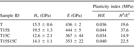
The Young's modulus, hardness and plasticity index of TaC-based composites (see Table II) are calculated from the load–displacement curves (plotted in supplement S5) using the Oliver–Pharr indentation method.Reference Oliver and Pharr34 Vickers' hardness for TaC is observed to increase from 15.5 to 19.5 GPa with the addition of SiC while it decreased to 12.5 GPa with CNT addition, which is in agreement to that reported in the literature.Reference Hackett, Verhoef, Cutler and Shetty12,Reference Kim, Woo, Doh, Yoon and Shon35 For T15S, higher relative density and grain refinement (Table I) leads to increased hardness values (Table II). The decreases in hardness value with CNT addition in T15C and T15S5CReference Chen, Balani and Agarwal36–Reference Singh, Diaz, Balani, Agarwal and Seal40 (showing lower value than that of base TaC), is attributed to agglomeration and damage of CNTs, which is confirmed by the electron microscopy and Raman analysis, respectively. The hardness of graphite (i.e., graphitization of CNTs during SPS processing) is reported to be in the range of 0.2–1 GPa.Reference Lee, Wei, Kysar and Hone41
Hardness and Young's modulus of processed TaC based composites measured using instrumented indentation technique.
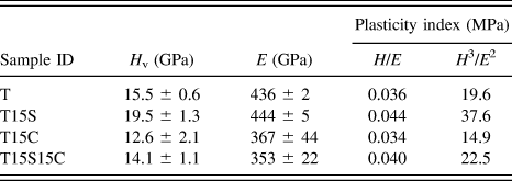
The measured Young's modulus of TaC is ∼436 GPa at theoretical densification of ∼93%, which is in agreement with that of the reported value.Reference Zhang, Hilmas and Fahrenholtz14 The measured value increased to 444 GPa with SiC addition, while it decreased to about 353 GPa with CNT addition. Although, CNTs possess high elastic modulus of 600–1000 GPa,Reference Peng, Locascio, Zapol, Li, Mielke, Schatz and Espinosa42 which may actually enhance the elastic modulus, but graphite possesses a low modulus of 10–15 GPa,Reference Lee, Wei, Kysar and Hone41 which has led to a decreased elastic modulus value for T15C (367 GPa) even though it exhibits a higher densification (∼97.6%). Flaky graphitic structure, resulted due to deformation and shearing offReference Lee, Wei, Kysar and Hone41 of CNTs during SPS processing, may not contribute toward the stiffness and thus, the modulus. The H/E ratio and H 3/E 2 determined experimentally by instrumented indentation (Table II) show similar trend of hardness and modulus with SiC and CNT reinforcement, confirming the resistance to plastic deformation.
E. Deformation and consolidation mechanism of CNTs during SPS
Structural stability of CNTs is essential in rendering enhanced toughness in TaC-based composites. As shown in Fig. 4(e), some of the CNTs are found intact even after being subjected to severe SPS processing conditions at 1850 °C (also see schematic in supplement S6). The confinement of CNTs in a singular intergranular region after transformation (observed in TEM micrographs) leads to a higher fracture strength and toughness, as discussed later in Sec. III. F. Buckling of CNTs due to the hydrostatic compressive stresses can be quantified either using molecular mechanics and atomistic simulations or utilizing Raman spectra.Reference Yakobson, Brabec and Bernholc43,Reference Zhang, Khare, Belytschko, Hsia, Mielke and Schatz44 Continuum mechanics expresses that the buckling pressure (P B) for the collapse of tubes can be predicted as:
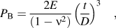 $${P_{\rm{B}}} = {{2E} \over {\left( {1 - {\nu ^2}} \right)}}{\left( {{t \over D}} \right)^3}\quad ,$$
where E is the elastic modulus, ν is the Poisson's ratio (=0.27), t is the thickness (considering it to be 5 nm for CNTs), and D is the diameter (∼40 nm for used CNTs) of the tube. Based on these values, the P B turns out to be 0.0042E for the CNTs. The room temperature elastic modulus for multiwalled CNTs has been reported as 21 ± 7 GPa.Reference Muthaswamy, Zheng, Vajtai, Shehkawat, Ajayan and Geer45 Thus, the pressure required for collapse and buckling of CNTs at room temperature is ∼88.5 MPa. However, at processing temperature of 1850 °C during SPS, this collapse may occur at much lower pressure. This observation is similar to that of Huang et al. who have reported a marginal increase in I D/I G ratio due to current induced damage in CNTs.Reference Huang, Jiang, Ovid’ko and Mukherjee46 Also, Zhang et al. have reported damage to CNTs and formation of submicrometer sized diamond during SPS even at 1500 °C and 80 MPa pressure.Reference Zhang, Khare, Belytschko, Hsia, Mielke and Schatz44 The retention of CNTs after SPS processing may be attributed to the high hardness of TaC, as CNTs may slip off to the void region formed between the mating TaC particles [as seen from Fig. 4(e) and Raman spectra in Fig. 3].
F. Effect of residual stress on the fracture energy of TaC–SiC–CNT composites
The fracture strength and toughness depends on the content of SiC and CNT reinforcement (ignoring the effect of size and distribution) in TaC matrix, and occurrence of interfacial compressive stress field (between reinforcement and matrix) in the TaC based composites. The fracture strength is observed to increase by 3.7, 4.1, and 7.8 times, respectively, with in T15S, T15C, and T15S15C when compared to that of T. Due to limitation of material and processing, only two set of samples were diametrical-compression-tested and the values obtained were within reported statistical limits. The load versus displacement relationship during the diametrical compression test is shown as supplement S7. Fracture energy of the samples was measured using area under the curve (in supplement S7) and then further related with the fracture toughness of the TaC-based composites (see Table III).
Theoretical calculation of modulus (E), thermal residual stress (σm, σr), fracture strength (σ), and fracture energy ratio of TaC based composites.
a Confidence limit > 95%.
Interfaces and structure of various phases of the TaC-based SPS composite pellets are elicited in TEM micrographs [Figs. 5(a)–5(d)]. The powder analysis via TEM (not presented here) also elicited distribution of SiC and CNT in the TaC matrix. It is established from Fig. 5(a) that SiC is encapsulated in the TaC matrix and the presence of carbonaceous material is observed between TaC grains [Fig. 5(b)], both constrained at the triple point junction without interconnects. Again, along with the presence of anisotropic TaC grains, Fig. 5(c) shows the presence of both SiC as well as transformed CNTs. However, the detailed micrograph of the transformation of CNT into layered graphite [as also observed in Fig. 5(b)] is shown in Fig. 5(d), which is in agreement with that observed from Raman spectroscopy (Fig. 3) and fractured microscopic analysis (Fig. 4). To distinguish present phases, i.e.; TaC, SiC, and CNTs, selected area electron diffraction (SAED) patterns were taken from different regions [Figs. 5(e)–5(g), respectively]. The indexed SAED pattern in Figs. 5(e) and 5(f) correspond to TaC [zone axis [212], Fig. 5(e)] and 6H–SiC [zone axis [111], Fig. 5(f)]. The nanocrystalline nature of the transformed CNTs into flaky graphitic structure was also indexed and is shown in Fig. 5(g).
Bright field TEM micrographs of the TaC based composites (a) T15S (b) T15C, and (c) T15S15C showing SiC and CNT sits at the intergranular junctions (d) transformed CNTs showing bending and deformation occurred in T15S15C sample. SAED pattern showing (e) cubic TaC in (a) (f) hexagonal SiC in (a) and (g) nanocrystalline graphitic system in (g).
Schematic illustration of the effect of residual compressive stresses on fracture toughness of TaC based composites (a) T, (b) T15S, (c) T15C, (d) T15S15C and correlated with the microstructure showing toughening mechanisms such as crack deflection, branching and bridging with reinforcement of (e) SiC, (f) CNT, and (g) SiC as well as CNT in TaC.
To understand the mechanisms of fracture toughness in TaC-based composites, interfacial residual stresses between the reinforcement and matrix is analytically computed. The fracture toughness (measured using Palmqvist indentation methodReference Anstis, Chantiklul, Lawn and Marshall27) is observed to increase with SiC and CNT addition, when compared to that of monolithic TaC (Table III), and showed a similar trend as that of tensile strength. The indentation fracture toughness of TaC matrix (∼3.1 MPa m1/2, which is in good agreement with the published resultReference Nieto, Lahiri and Agarwal24) is increased to ∼5.8, 8.9, and 11.4 MPa m1/2 for T15S, T15C, and T15S15C, respectively. To access the role of thermal expansion, coefficient misfit between the matrix and reinforced materials on toughening is quantified by the proposed model. Generation of such stresses may favor interfacial debonding as observed through pullouts in the fractographs [Figs. 4(c)–4(e)]. The mismatch in thermal expansion coefficient of matrix and reinforced particles create interfacial compressive stress field in the composite and play a vital role in dictating toughening mechanisms in UHTCsReference Yang, He, Su, Reppert, Skove, Tritt and Rao47 due to their high operational temperature. This interfacial compressive stress lowers the high tensile stress in the matrix, and, thus, favors crack closure. The quantification of such thermal residual stresses in composites becomes primarily important, since processing has been carried out at very high temperature where these stresses develop (ΔT), due to the difference in coefficient of thermal expansion (CTE) . It has been reported in literature that stresses begin to accumulate at 1400 °C during cooling from the processing temperature for ZrB2 based UHTCs.Reference Ghosh, Subhash and Orlovskaya48,Reference Watts, Hilmas, Fahrenholtz, Brown and Clausen49 Since the composites are being cooled from the final densification temperature (1850 °C) to room temperature; TaC (CTE ∼ 7.1 × 10⁻⁶ K−1) tends to shrink faster than the reinforced particles (SiC, CTE ∼ 3.5 × 10⁻⁶ K−1, and CNTs, CTE ∼ 2.5 × 10⁻⁶ K−1).Reference Silvestroni, Pienti, Guicciardi and Sciti50 This leads to the generation of tensile stress state in the matrix, σm, and corresponding buildup of compressive stress in the reinforced particles, σr, can be evaluated using Taya's model,Reference Taya, Hayashi, Kobayashi and Yoon51 (tabulated in Table III):
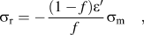 $${\sigma _{\rm{r}}} = - {{\left( {1 - f} \right)\varepsilon '} \over f}{\sigma _{\rm{m}}}\quad ,$$
 $${\sigma _{\rm{m}}} = + {E_{\rm{m}}}{{2f\beta \varepsilon '} \over {\left( {1 - f} \right)\left( {\beta + 2} \right)\left( {1 + {\nu _{\rm{m}}}} \right) + 3\beta f\left( {1 - {\nu _{\rm{m}}}} \right)}}\quad ,$$
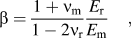 $$\beta = {{1 + {\nu _{\rm{m}}}} \over {1 - 2{\nu _{\rm{r}}}}}{{{E_{\rm{r}}}} \over {{E_{\rm{m}}}}}\quad ,$$
 $$\varepsilon ' = \left( {{\alpha _{\rm{r}}} - {\alpha _{\rm{m}}}} \right)\Delta T\quad ,$$
where, f is the volume fraction of the reinforcement;  ${E_{\rm{r}}}$,
 ${E_{\rm{m}}}$,
 ${\nu _{\rm{r}}}$, and
 ${\nu _{\rm{m}}}$ are the Young's modulus and Poisson's ratio (taken as 0.27, 0.14, and 0.17, respectively, for TaC, SiC, and CNTs)Reference Silvestroni, Pienti, Guicciardi and Sciti50 of the reinforcement and matrix, respectively;
 $\varepsilon '$ is the thermal expansion misfit strain;
 ${\alpha _{\rm{r}}}$ and
 ${\alpha _{\rm{m}}}$ are the CTE of reinforcement and matrix, respectively (taken as 7.1 × 10⁻⁶ K−1, 3.5 × 10⁻⁶ K−1, and 2.5 × 10⁻⁶ K−1 for TaC, SiC, and CNTs, respectively)Reference Silvestroni, Pienti, Guicciardi and Sciti50 and
 $\Delta T$ is the temperature at which stresses begin to accumulate (base temperature set as 1400 °C). Young's modulus, E r for each composite is experimentally measured using instrumented indentation technique and modulus for each phase is estimated using the rule of mixture considering modulus of matrix E m of TaC) as 435.9 ± 24.4 GPa.
Apart from the toughening resulting from the usual toughening mechanisms (such as crack-deflection, CNT crack-bridging, crack-divergence, etc.), a noticeable change in the indentation fracture toughness value of TaC with addition of secondary phases is attributed to the residual stresses developed in the matrix (see Table III). The value of compressive residual stress ranges from ∼7.6 to 10.6 MPa with the SiC and CNT reinforcement, which remains almost the same (∼5% of that in matrix), see Table III. Whereas, it is evident (in Table III) that residual tensile stress in the matrix is observed to be the least for T15S15C (∼195 MPa) when compared to that of T15S (∼310 MPa) and T15C (∼220 MPa). Thus, it is indicated that the reduction in the tensile stress at the matrix interface dominates over the compressive stress in the reinforcement, and is observed to correlate well with the trend of fracture energy, and fracture toughness obtained for TaC-based composites. Apparently, T15S15C has shown highest fracture toughness (∼11.4 MPa m1/2) when compared to that of other TaC-based composites (i.e., 3.1, 5.8, and 8.9 MPa m1/2, respectively, for T, T15S, and T15C), eliciting a synergistic reinforcement of SiC and CNT in TaC matrix. It may be mentioned that the isolated contribution of CNT-bridging, crack-deflection, and CNT pullout is not quantified, but the interfacial residual stress does indicate the trend of how the fracture toughness is affected by various reinforcements. A schematic illustration of the effect of residual stress on affecting fracture toughness of composites with SiC and CNT reinforcement in TaC matrix is presented in Fig. 6. The improvement in the fracture toughness values with SiC and CNT reinforcement is subjected to the extent of adhesion of secondary phase with the matrix, supplemented by the TEM micrographs in Figs. 5(a)–5(c). The secondary compressive forces acting between the TaC and SiC interface have shown to reduce the effective residual tensile stress (∼310 MPa) in T15S [Fig. 6(b)] as mentioned in Table III. Figure 6(c) shows that fibrous nature of the CNTs enhance the anchoring [or pullout, Fig. 4(e)] with the TaC matrix, leading to further decrease in the effective residual tensile stress (∼220 MPa). A synergistic improvement in the adhesion zone due to reinforcement of both SiC and CNT, in T15S15C, has led to a further reduction in the interfacial tensile residual stress (i.e., to ∼195 MPa) of TaC, which is proportional to the toughness improvement [Fig. 6(d)] when compared to that of pure TaC [Fig. 6(a)]. The fracture toughness of TaC with synergetic addition of SiC and CNT is enhanced by almost ∼8 times (i.e., from ∼3.1 to 11.4 MPa m1/2) because of the intrinsic energy dissipating mechanism such as CNT-bending, CNT-bridging, crack deflection [Figs. 6(e)–6(g)], and interfacial residual stresses are found to be consistent with the value of fracture-energy ratio listed in Table III. Thus, the intrinsic CNT energy dissipation mechanism along with the interfacial residual stresses resist the crack propagation (via crack deflection and rendering high energy path) result an enhanced toughness of the SiC and CNT reinforced TaC composites.
IV. CONCLUSIONS
TaC based composites were successfully spark plasma sintered with densification ranging between ∼93 and 98%. The decrease in the hardness values of TaC (from 15.5 to 12.6 GPa) with CNT addition was attributed to the partial transformation of CNTs into graphitic structure as confirmed by increase in I D/I G ratio, which was further supplemented by TEM, however, some CNTs do remain intact even after SPS processing. The synergistic addition of SiC and CNT enhanced fracture toughness from 3.1 to 11.4 MPa m1/2 of TaC based composite. Thus, incorporation of SiC and CNT (in T15S, T15C, and T15S15C) generate beneficial compressive residual stresses at the interface during SPS. The reduced interfacial residual tensile stresses, generated in the matrix, were observed to be inversely proportional to the fracture toughness, and elicited a corresponding increase in the fracture energy with synergistic reinforcement of SiC and CNT in TaC matrix. Thus, enhanced performance (e.g., fracture toughness) of T15S15C gives them an edge over T, T15S, and T15C as a candidate damage-tolerant structural material for high temperature applications.
Supplementary Material
To view supplementary material for this article, please visit http://dx.doi.org/10.1557/jmr.2016.65.
ACKNOWLEDGMENTS
Authors acknowledge the financial support received from IITK-Space Technology Cell and ISRO (Indian Space Research Organization), Trivandrum, India. Authors also acknowledge Electron Microscope Facility, MSE Department, IIT Kanpur, and instrumented indentation facility and mechanical testing in Advanced Center for Materials Science, IIT Kanpur. K.B. acknowledges P.K. Kelkar Fellowship, IIT Kanpur.