

INTRODUCTION
Recent years have witnessed an increasing awareness of the use of long-distance alignments in Roman surveying and planning practices, not just in Britain but across the Empire.Footnote 1 For the author, the initial discovery came in 2004–5, while investigating the direction of planning of Roman Dere Street, from the Vale of York to Newstead in Scotland. This revealed that much of the course of that Roman road had been based upon a framework of long-distance alignments, from which, in places, deviations had been made. Typically, these deviations seem to have been undertaken in order for the road to reach suitable crossing-places over major rivers, to service important sites off the alignments or to avoid unsuitable ground — after which the course of the road would often return to the long-distance alignment.Footnote 2 This discovery had been completely unexpected at the time, but, since then, particularly via the work of Robert Entwistle, many more examples of the same process of planning have been identified along Roman roads in other parts of BritainFootnote 3 and it seems likely that this was a fairly standard procedure for setting out the course of Roman roads, at least in the early conquest periods. It must be stressed that not all Roman roads in Britain appear to have been planned in this way, but in a previous publicationFootnote 4 the author offered a practical explanation of how and why such long-distance alignments could have been set out and then deployed in helping to determine the courses of certain Roman roads.
When, following the work on Dere Street, the author sought to examine the directions of planning of Hadrian's Wall, it became clear that the same mixture of long-distance alignments and deviations had been employed when laying out the line across the countryside. This is not necessarily the best way of setting out a wall across an undulating landscape and, at the time, it was assumed that the Roman surveyors must simply, but rather unimaginatively, have adopted the process with which they were most familiar — i.e. one which they apparently used when setting out the lines of some of their roads.Footnote 5 However, in the light of the new discoveries about the planning of the Antonine Wall, described below, it now seems possible that the Roman surveyors may have been aiming to facilitate lateral communication along the line of Hadrian's Wall, as an adjunct to their primary objective of signalling to the forts and fortlets along the Stanegate.Footnote 6
Naturally, in the light of the discoveries along Dere Street and Hadrian's Wall, when attention turned to the planning of the Antonine Wall in Scotland, a search was specifically made for any long-distance alignments which might have underpinned the line of that Wall as it ran across the Forth-Clyde isthmus (fig. 1). Apart from a single isolated and rather short-ranged example,Footnote 7 however, no such alignments were detected. Instead, the line of the Wall was found to be predominantly sinuous in nature. In contrast, the installations along the Antonine Wall — the forts and fortlets, etc. — were observed to follow a much less sinuous course across the countryside than that of the Wall. Moreover, although the evidence was incomplete, there appeared to be strong indications that each of the military installations along the Antonine Wall had been positioned so as to be inter-visible (at tower heightFootnote 8) with its nearest neighbours to east and west. If so, this would seem to imply that these installations had been so positioned as to be able to signal to their immediate neighbours and, in practical terms, it is highly unlikely that this could have been achieved had not their locations all been planned at the outset. This would suggest that, for the Antonine Wall, all the military installations had been laid out first and that the line of the Wall, i.e. the rampart and ditch, had then been set out to link each installation to the next by taking the best advantage of the ground in between.Footnote 9
Known military installations along the Antonine Wall, showing the locations of the enclosures, expansions and towers to which reference is made in the article.

This conclusion runs counter to the prevailing perception that several of the military installations along the Antonine Wall had been added or modified as afterthoughts, as the result of one or more changes of plan during the operational existence of the Wall. The difference between these two opposing views has now become a matter for debate.Footnote 10 As it happens, one outcome from the present paper, which will be discussed in the concluding section, appears to add weight to the view that all the military installations along the Antonine Wall had been planned at the outset. Rather than engage in the debate, however, the purpose of this paper is simply to report the new discoveries and to offer what would seem to be the likeliest interpretation for what has now been found.
NEW EVIDENCE
Based upon investigations which had been conducted down to 2009, the author had declared that no significant long-distance alignments had been found to underpin the course of the Antonine Wall.Footnote 11 This situation changed in 2014, when, at the suggestion of Erik Graafstal, an exercise was undertaken to examine, at a viewing height of 7.6 m above ground level, the inter-visibilities between all the military installations along the Antonine Wall, including the small features attached to the rear of the rampart which are known as enclosures and expansions.Footnote 12 At the time it was unclear what this exercise would contribute, but with modern digital mapping, using Ordnance Survey (OS) 1:50,000 data in digital form and Fugawi software, it was a straightforward if somewhat laborious desktop exercise to undertake, albeit with the need for some on-the-ground verification in certain places.
The results are presented in online table 1, while online table 2 lists the OS grid references which were used for the location of each installation.Footnote 13 online table 1 clearly illustrates that inter-installation signalling facilities could have existed along the Wall line, with many of the forts and fortlets being visible from more than their immediate neighbours. The chief uncertainties concern the inter-visibilities around the fort at Bearsden and the arrangements east of Inveravon, where extensive modern build-up may obscure undetected Roman remains.
For completeness, the inter-visibilities were also checked with those forts which might appear to have been peripheral to the Antonine Wall, i.e. those at Bishopton, Camelon and Carriden. While the results will be addressed in detail later in the paper, in advance it is worth noting the exceptional range of inter-visibilities which Camelon appears to have possessed. From the fort's south gate, all the known military installations at the eastern end of the Antonine Wall, from Kinneil to Rough Castle, would have been inter-visible with it. At a much greater distance, the fortlet on Croy Hill and the stations on Bar Hill would also have been inter-visible with it. This appears to mirror the situation near the western end of the Wall, where, as indicated in online table 1, a tower located at the fort at Castle Hill would have been able to observe not only most of the installations along the western half of the Wall, from Duntocher up to Bar Hill, but also many of the installations beyond, up to and including the fort at Rough Castle. This raises the possibility that Castle Hill and Camelon might have been able to serve as communications hubs for the western and eastern ends of the Wall respectively.Footnote 14
These results in themselves were illuminating about the degree of planning which appeared to have gone into selecting where to position the Wall's installations, but it was only when the lines of inter-visibilities between each of the installations were drawn on a map that the more significant discoveries were made. Initially, this mapping had been undertaken purely for illustrative purposes, but what emerged was that several of the lines of inter-visibility appeared to pass exactly over other installations. For instance, the line of sight between the expansion at Bonnyside West and the fortlet on Croy Hill proved to pass directly over the forts at Castlecary, Westerwood and Croy along the way. At first these occurrences were dismissed as coincidences; after all, as already noted, the installations along the Antonine Wall did follow a line which curved only gently, so that some overlapping of the lines of inter-visibility could be expected. As the mapping progressed, however, the frequencies with which these overlaps continued to occur made it obvious that they needed to be taken more seriously, since it appeared that they might have been deliberate.
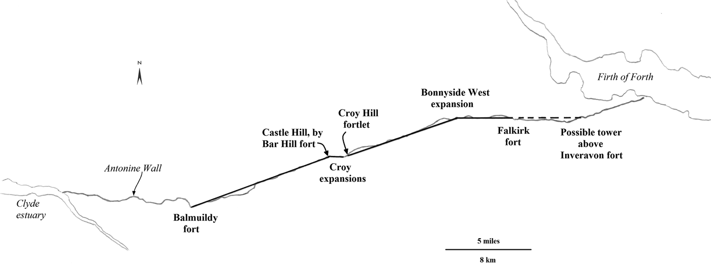
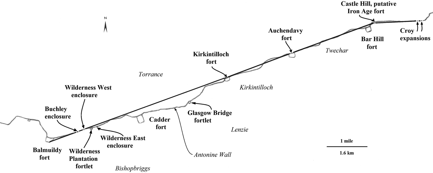
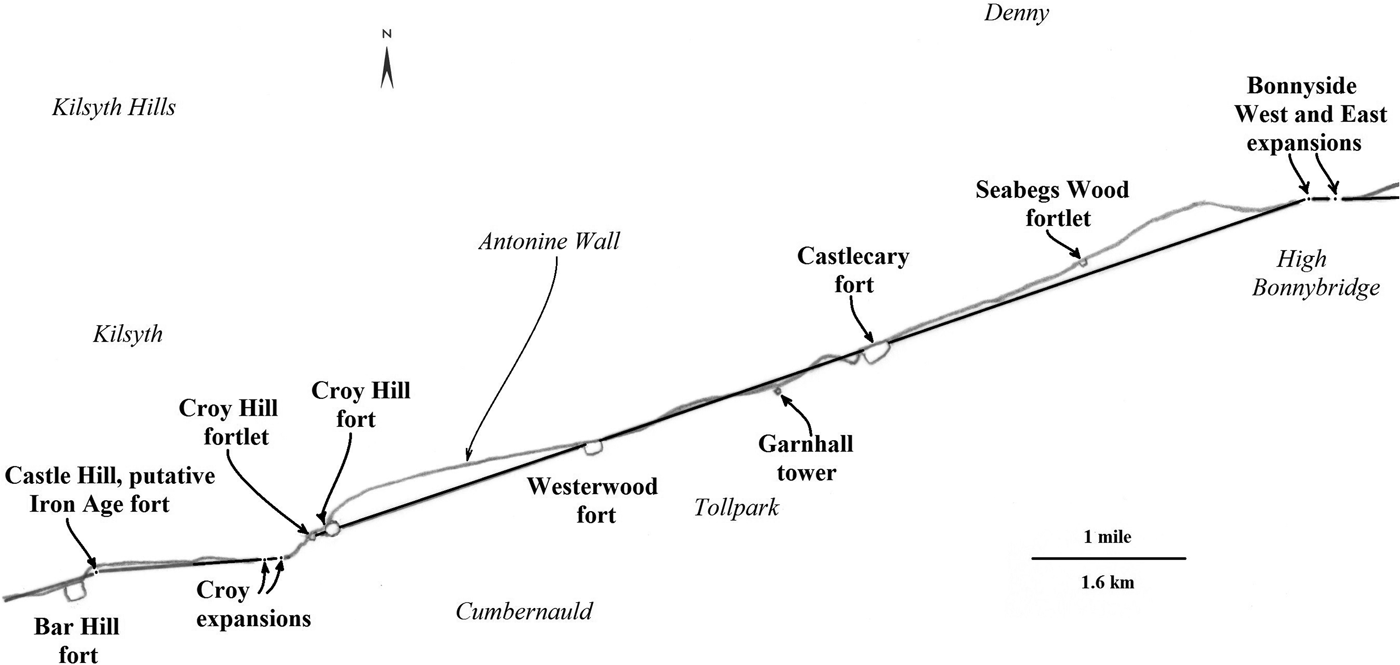
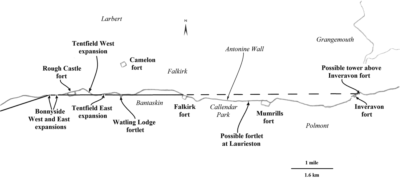
When this possibility was analysed across all the sites, what emerged were three long-distance alignments and a short dog-leg, upon which the majority of the Wall's central installations appeared to have been located (see figs 2–5). These alignments were:
(a) from the fort at Balmuildy to Castle Hill,Footnote 15 just to the north of the fort on Bar Hill;
(b) a short dog-leg from Castle Hill to the expansion at Croy East on Croy Hill;
(c) from the fortlet on Croy Hill to the expansion at Bonnyside West;
(d) from the expansion at Bonnyside West to the fort at Falkirk, possibly continuing to a towerFootnote 16 above the fort at Inveravon.
Overview of the long-distance alignments spanning the central sectors of the Antonine Wall.

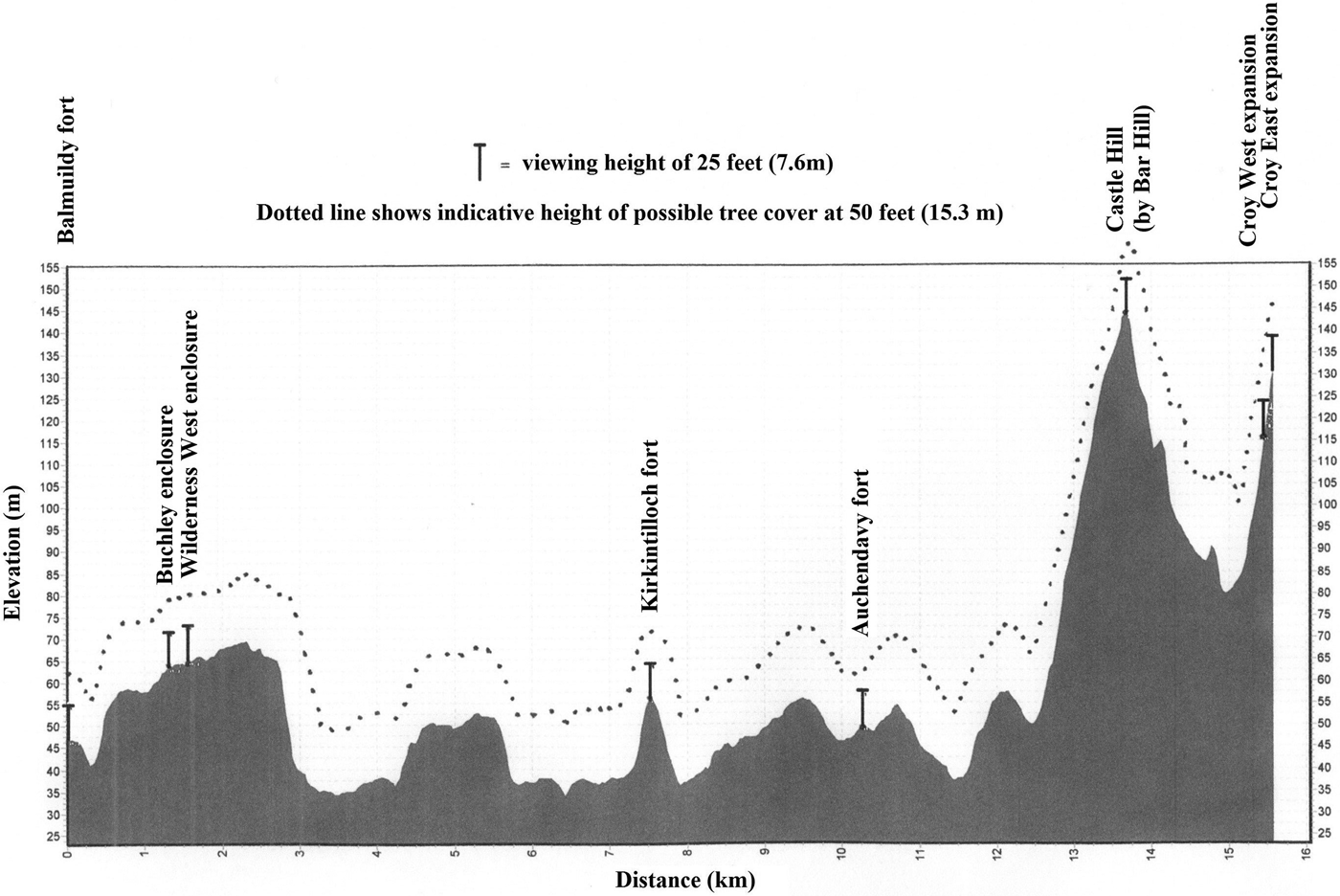
The alignments from the fort at Balmuildy to Castle Hill and from Castle Hill to Croy West and Croy East expansions. Castle Hill is the site of a putative Iron Age fort which appears likely to have been reused by the Romans as an observation and signalling post (see note 15). The enclosures at Buchley and Wilderness West and the forts at Kirkintilloch and Auchendavy stand exactly upon the alignment between Balmuildy and Castle Hill, and the Croy West and East expansions are exactly aligned upon Castle Hill.

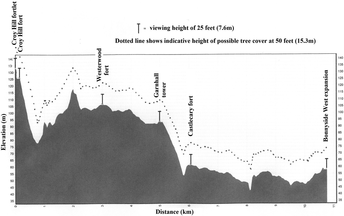
The alignment from the fortlet on Croy Hill to the expansion at Bonnyside West. The forts on Croy Hill, at Westerwood and at Castlecary stand exactly upon this alignment.

The alignment from the expansion at Bonnyside West to the fort at Falkirk with a possible extension to the tower above the fort at Inveravon (see note 16 for the possibility that the latter site may have had a Roman origin). The expansion at Bonnyside East, the south-west corner of the fort at Rough Castle, the expansion at Tentfield East and the fortlet at Watling Lodge all fall upon this alignment.

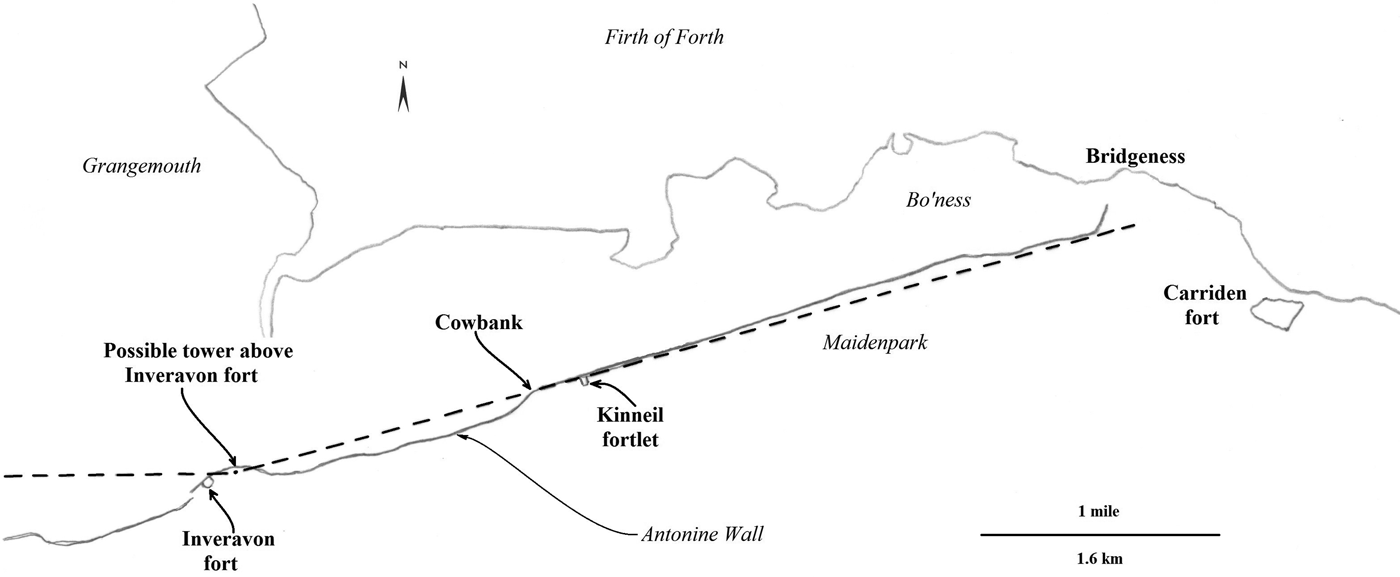
Elsewhere, no long-distance alignment was detected along the installations west of Balmuildy, while east of Inveravon it is possible that an alignment may have helped to fix the rather curious position of the fortlet at Kinneil, which is set back c. 62 m from the edge of the cliff it was presumably intended to overlook; the remainder of the evidence at the eastern end of the Wall seems rather less clear (see fig. 6 for further details about this possibility).Footnote 17
A possible alignment which may have been used to help set out the course of the Antonine Wall from Kinneil to Bo'ness. The alignment runs from the potential tower above the fort at Inveravon to the high ground above Bridgeness. Where this line crosses the edge of the cliff overlooking the Carse of Falkirk, at Cowbank, the character of the course of the Wall changes abruptly, from being almost straight to the east but notably sinuous to the west.

From figs 3–5, it can be seen that not only do the majority of the central forts and fortlets of the Antonine Wall lie upon long-distance alignments, but so do the majority of the known enclosures and expansions, and exactly so, too. The possibility that all this could have happened by chance can be readily dismissed as highly improbable. Overall, there seems little doubt that the existence of these long-distance alignments was indeed deliberate and that they had played a dominant role in determining the positioning of many of the military installations along the central sections of the Wall.
POSSIBLE EXPLANATIONS
Arguably the existence of these alignments represents a significant discovery. Naturally, the question which arises is why the Romans would have sought to ensure that so many of their military installations along the Antonine Wall should stand exactly in line.
It seems unlikely that it would have been for political reasons. Even if there were some need to negotiate a boundary between the Roman and native interests to the south and north of the Forth-Clyde isthmus, it would surely have been more sensible to set the line out along the low-lying valleys of the Kelvin, Bonny Water and Carron — which run just to the north of the Antonine Wall — rather than upon a trio of dog-legged alignments straddling the hilly ground behind. Even today, the floors of these three interlinked valleys are largely a marshy zone prone to flooding, surely a substantial enough obstacle to movement and a much more logical natural boundary of choice for both parties had they sought one.
Nor is it inherently necessary for military installations to be positioned exactly in line for operational reasons — as may be observed, for instance, with the forts and fortlets along the Stanegate, to the rear of Hadrian's Wall. Admittedly, not all the Stanegate's installations were erected at the same time, but, closer to home, the Romans did not apparently consider it necessary for their installations to lie in line along the Antonine Wall to the west of Balmuildy. The long-distance alignments only seem to have existed in connection with the commanding heights of Bar Hill and Croy Hill, and with the break of views to east and west which occurs on the high ground between Rough Castle fort and the fortlet at Watling Lodge, in Tentfield Plantation.
There are, however, certain operational advantages which arise from having installations exactly in line:
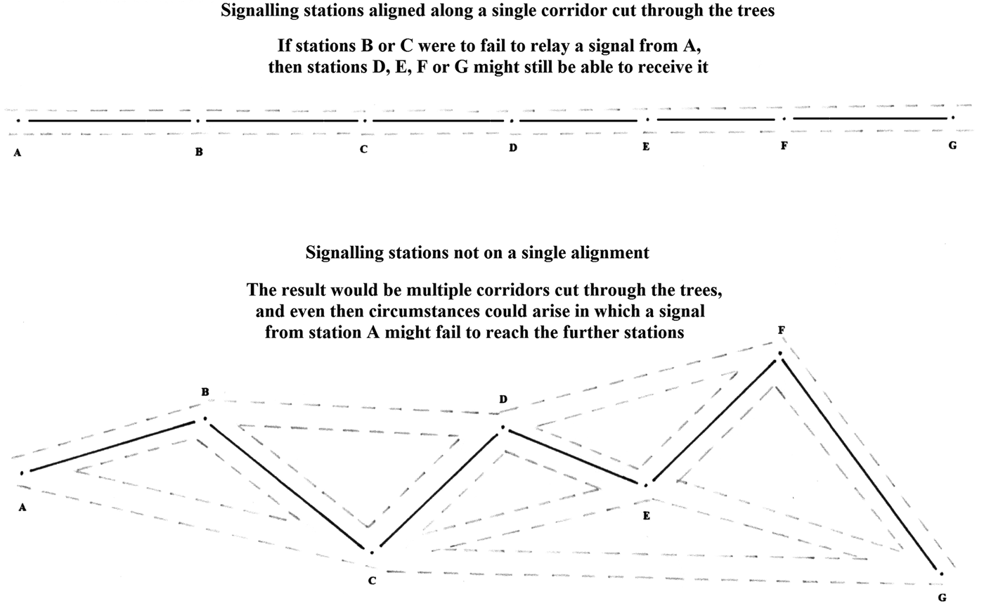
(a) if there were a scattering of trees in the landscape (n.b. it would not have to have been thickly woodedFootnote 18), only a single visual corridor would need to have been cut through the trees and kept open for observation and signalling;
(b) for signalling purposes there would also have been a degree of redundancy, in that if one installation failed to relay a signal, others in the line might still have been able to pick it up, as illustrated in fig. 7;
(c) a chain of installations would have offered a station-to-station fall-back mode for long-distance signalling in the event of reduced visibility;
(d) it would have reduced the risk of deception from bogus signals, potentially created by hostile forces so as to mislead Roman responses, but which, in practice, would normally have had to be created off the line.
One advantage of having signalling stations in line across a wooded landscape.

It might be wondered how, if a chain of installations is exactly in line, it would be possible to determine from which installation a signal might or might not be coming — for instance, when on look-out in the dark. The answer is that because of natural rises and falls in the landscape, the installations would almost inevitably have stood at different heights relative to their neighbours, when viewed from any other installation. Hence a series of notches or pegs driven into the timberwork of each viewing station, rather like gun sights, would have enabled observers to distinguish precisely from which installation a signal might or might not have originated. This arrangement would also have helped to differentiate between bogus and genuine signals.
POSSIBLE ALARM SYSTEM
When examining the landscape crossed by the Antonine Wall, it can readily be appreciated that the commanding heights of Croy Hill and Bar Hill, in particular, would have made them outstanding vantage points for long-distance observation. However, it would also have made them ideal locations for broadcasting alert signals, in clear conditions, to many of the forts and fortlets along the line of the Wall, with the added advantage of being able to do so virtually simultaneously (see figs 8 and 9).
Profile of the land along the alignment from Balmuildy to Castle Hill and then across to Croy East expansion. Note that the indication of tree heights is not meant to imply that this landscape would have been thickly wooded. Rather, even if only a scattering of trees had been present then the dotted line shows where, at a height of 15.3 m, they could have obstructed the views between the various military installations along the alignment. In practice fully grown oak, birch, and even alder, could have stood considerably higher than 15.3 m, but hazel less so.

Profile of the land under the alignment from Croy fortlet to Bonnyside West expansion. With regard to the indication of tree heights, see the caption for fig. 8. Note: the tower at Garnhall is some 80 m off the alignment.

It is possible that this second point is why the Romans set out so many of the installations to be exactly in line in the central sectors of the Wall. For raising a general alarm over long distances, the foregoing benefits from having all installations in line would have been intensified, not least with regard to the deployment of a fall-back mode and the reduced chances of being deceived by bogus signals. Perhaps more importantly, though, if it was also standard practice for each fort and fortlet to fire a beacon whenever an alarm signal had been spotted, this would have enabled the commanders at each installation to judge by a glance in each direction which installations had received the signal and which had not. This would have been key information to have had in an emergency situation. Having all the installations in line would have facilitated this, whereas having them scattered across a landscape — even one sparsely populated with trees — would not.
As it happens, excavations beneath both the forts on Bar Hill and on Croy Hill have revealed the remains of structures which preceded their erection. Usually referred to as camps, neither actually resembles other Roman camps. Instead, they might have been small enclosed areas which, from their elevated positions, may have housed facilities for setting out the long-distance alignments to the west and east of the two central hills. This possibility will be examined in more detail below.
Even so, for the specific purpose of raising a general alarm, it is not absolutely essential for all the installations to have been positioned exactly in line and the Antonine Wall apparently offers the observer a limited number of examples of divergence from the alignments, seemingly for entirely practical reasons in each case. Details of these examples are, again, discussed below.
POTENTIAL ROLES OF THE ENCLOSURES AND EXPANSIONS
Returning to the Antonine Wall itself, what is noticeable is that the known enclosures and expansions only occur where the alignments have been detected. Indeed, the majority happen to lie exactly on the long-distance alignments, and therefore it appears that the two features were connected in some way. This picture could, of course, change were more enclosures and/or expansions to be discovered, but so far, even with the advantage of modern technological aids such as geophysical surveys, aerial photography and LiDAR, there is no indication that they were studded along the entire length of the Wall.
There are three known enclosures, at Buchley, Wilderness West and Wilderness East, all standing close by the fortlet at Wilderness Plantation, to the north-east of Balmuildy. Discovered by aerial photography in 1977, only one of them — at Wilderness West — has so far been examined by excavation.Footnote 19 Six of the expansions, which occur in pairs at Croy West and East, Bonnyside West and East, and Tentfield West and East, have been known to observers for a long time, while a seventh may have been found more recently during limited excavation at Inveravon in 1991.Footnote 20 The two expansions on Croy Hill were initially examined in the nineteenth century; that at Croy East was reopened in 1967, while the expansion at Bonnyside East was fully excavated in 1957.Footnote 21
The enclosures differ from the expansions in being surrounded by a ditch. This apart, there are similarities between the two types in that, despite extensive examination, no signs of any internal timberwork or structure have been found in any of the investigations to date, except for a single post-hole in the possible expansion at Inveravon. In addition, the size of the area at the one enclosure which has been excavated was almost exactly the same as that occupied by an expansion.Footnote 22
Numerous explanations have been advanced as to the function or functions of these enigmatic structures, but so far archaeological excavation has failed to provide an unequivocal answer, let alone indicate whether the functions of the two types of structures might have been the same or different. Hence it seems apt to see what might be deduced from their positions in the landscape and their possible relationships to other features along the Antonine Wall, including the newly found alignments.
As already noted: (a) the enclosures and expansions only seem to occur where the long-distance alignments have been found; (b) all but one of the six long-known expansions, and two out of the three more recently discovered enclosures, lie exactly upon the long-distance alignments. In addition, all are attached to the rampart of the Wall. This has led to the following proposals for their possible functions:
(1) That they were beacon sites, employed for raising an alarm. This possibility was firmly advocated by Kenneth Steer in the report of his excavation of the expansion at Bonnyside East and it apparently concurs with the view previously reached by Sir George Macdonald.Footnote 23 However, Steer envisaged that the need for such an alarm system would have been ‘to arouse the garrisons of Clydesdale’ to serious threats which had been spotted approaching the Antonine Wall from the north.Footnote 24 He thus saw that the alarm would have been raised from Rough Castle fort via the Bonnyside expansions, before being transmitted southwards to Clydesdale via the expansions on Croy Hill. Unfortunately, since Steer's time, archaeology has failed to locate any Roman forts lying south of Croy Hill which were unequivocally occupied in the Antonine period and sufficiently close to be able to receive such a signal with any reliability. The nearest fort which certainly appears to have been in use at the time is located at Bothwellhaugh, near Motherwell, c. 18.5 km from Croy Hill. However, it occupies a low-lying position close to where the South Calder Water joins the river Clyde and is thus not directly visible from the expansions on Croy Hill; to have enjoyed any form of visual communications between the two locations it would have required a chain of relay stations.Footnote 25
(2) That they were observation stands from which the soldiers could monitor the land to the north of the Wall. This might apply particularly if there were no wall-walk along the top of the rampart, as is sometimes proposed. However:
(a) some of the known enclosures and expansions do not appear to be in especially suitable positions for observation and there also seem to be examples of needless duplication in places;Footnote 26
(b) to date they have not been found at more sensitive points at which they might be expected;Footnote 27
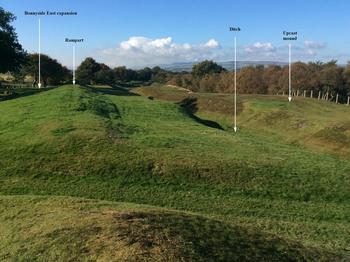
(c) the short- and medium-distance views northwards from the expansion at Bonnyside East appear to have been obstructed rather than facilitated by a pronounced rise in the upcast mound immediately in front, on the northern side of the ditch (see fig. 10).Footnote 28 Unless material had been dumped in post-Roman times — which does not appear to have been the case — this mound could not have grown after it was built.
FIG. 10.View westwards towards Bonnyside East expansion, showing the upcast mound to be raised in front of the expansion. (Photograph kindly provided by Mark Winter)


More importantly, as already noted, none of the enclosures and expansions excavated to date (except for the possible expansion at Inveravon) has revealed evidence for the kind of substantial permanent structure that would be required for an observation post.Footnote 29 To be at its most effective, a look-out post has to be continually manned, because it is important to be able to recognise that something — somewhere in the field of view — has changed or is abnormal; it is this which invariably gives the warning that trouble is about to occur.Footnote 30 This requirement for constant scrutiny calls for some kind of structural protection from the elements, in the climate of the Antonine Wall, not to mention from the unwanted attention of hostile marksmen.
(3) That they might have been platforms for Roman artillery. The objections to this idea are, though, similar to those against the notion that they were observation stands. Those which are known do not appear to be in particularly vulnerable positions which would have required artillery, nor have they yet been found where such devices might be expected to have been located. In addition, there is no indication that they possessed any kind of substantial structure which might have improved the effectiveness of their weaponry, while at the same time providing protection from native archers and slingers.
(4) That they could have carried steps or stairways, allowing soldiers access to the top of the Wall rampart. However, so few are known at present that this scarcely seems a practical proposition. Besides, portable ladders would surely have offered a more flexible and secure solution for such needs.
It is the first of these proposals which has found most favour among archaeologists, while, with regard to the preceding discussion, beacons are what would have been required for raising alarms rapidly over long distances. The fact that the expansions tend to occur in duplicate (or in triplicate for the enclosures) may provide a further clue to their intended purpose.
In his book on Roman Military Signalling, David Woolliscroft makes the point that beacon systems are, in comparison with more complex signalling systems, very limited in the information they can convey. Essentially, like a modern fire alarm, they simply alert people to the possibility of a threat, but not necessarily to where or how serious it might be. Effectively, therefore, an alarm signal amounts to no more than a call to action stations. Woolliscroft does, however, suggest that it would have been possible for the Romans to have operated a slightly more sophisticated two-level alarm system, in which one beacon lit meant ‘trouble’ while two beacons lit meant ‘serious trouble’.Footnote 31 Arguably such an arrangement could have been implemented along at least the central sections of the Antonine Wall, where a close examination of all the military installations between Balmuildy and Inveravon appears to offer opportunities for pairings right across the central sectors, rather than just where the enclosures and expansions happen to be located. Since, as far as the author is aware, there are no known reports of the existence of such a two-level alarm system elsewhere along the Roman frontiers, it will be appropriate to examine this possibility in some detail.
FEASIBILITY OF A TWO-LEVEL ALARM SYSTEM
At this juncture, because of the inevitable intricacies that are involved in any feasibility study and a recognition that not every reader will wish to pursue the details in depth, the full report of this aspect has been consigned to an Appendix, where those who wish to investigate the possibility in full may do so. For the rest of the readers, what the analysis seems to demonstrate is: (a) that a two-level alarm system would have been feasible; (b) how it might have worked. This does not prove that the Romans implemented such a scheme, but it shows that it would have been practical for them to have done so, given the disposition of their installations across the particular landscape of the Antonine Wall.
If such a scheme had indeed been implemented, it seems likely that the process of setting it out would have called for an extensive degree of surveying and testing, including the use of lights at night, and that facilities would have been required to achieve it. As already noted, on the two highest hills along the Antonine Wall, an enclosure or camp has been found to underlie the forts on Croy and Bar Hills. Rebecca Jones has commented that, as mentioned previously, neither of these resembles any known Roman camps and she suggests that they may have housed teams of surveyors engaged in the initial planning exercise.Footnote 32 Indeed, it seems eminently possible that they were used to help survey the newly discovered long-distance alignments. Such facilities, though, may have been needed to serve more purposes than merely surveying:
(a) to carry out testing during the erection of the various installations along the Wall, to ensure that they were in line and inter-visible;
(b) to confirm the working of the entire alarm scheme upon completion;
(c) to take part in routine testing and training exercises thereafter, to ensure that the troops knew how and when to fire the alarms and how to respond to them.
If these enclosures or camps were retained in commission for such purposes, they are likely to have been occupied for quite some time, a suggestion which is supported by certain archaeological indications. Jones, for instance, mentions that cobbling and burning were discovered in the remains under Bar Hill,Footnote 33 which seems to indicate sustained occupation. Later, when these enclosures or camps were replaced by the forts on Bar Hill and Croy Hill, the latter could then have assumed the residual functions which the original structures seem likely to have been performing.
With regard to the third long-distance alignment, from Bonnyside West expansion towards the east, the natural position for such a sighting and testing facility would have been at the break of view, on the high ground in Tentfield Plantation. This would have enabled both ends of the alignment to be set out in line and observations to be made about the positioning of the installations and the functioning of the scheme once in operation. It must be admitted, however, that no enclosure or camp has yet been detected at this location; while this remains a gap in the evidence, Tentfield Plantation has been thickly wooded since Victorian times at least, so further investigation here may prove fruitful.
The setting-up of such surveying and testing facilities would have called for a considerable effort on the part of the Romans, to the extent that it would seem to have been unwarranted had it not been really important for so many military installations to have been positioned exactly in line. Otherwise, forcing the installations along the Antonine Wall to do so for no specific purpose would have been a handicap to their construction, not a convenience. In fact, to the author, the creation of an alarm system would appear to offer the only practical explanation for the justification of such effort.
Finally, it should be emphasised that the proposed alarm scheme is envisaged as having been created to respond to threats of significant proportions. It would seem likely that opportunistic raids upon the Antonine Wall by small gangs of hostile natives would have been dealt with locally by soldiers in the nearest forts and fortlets. Serious military threats, involving the approach of many hundreds of men or even more, would have been of far greater concern to the Romans, especially since it has been pointed out that the Wall may have been quite lightly manned once completed and brought into commission.Footnote 34 In a military context, the strategic reason for building a wall is to achieve an economy of manpower. This is well understood nowadays and is unlikely to have been lost upon as militaristic an organisation as the Roman army; but, once the point had been grasped, it would clearly have heightened the need for an effective early-warning system. Thus it is possible that the conscious intention of keeping the Antonine Wall lightly manned, once commissioned, had been a principal stimulus for the creation of the proposed alarm scheme.
From the foregoing it can also be envisaged that control of such an alarm system would have been at a senior military level. As Woolliscroft points out, once a beacon has been fired, the alarm so raised is very difficult to cancel or countermand.Footnote 35 Thus it may be imagined that the frivolous triggering of such a system by a fearful sentry would not have been allowed. If necessary, any such emergencies would have called for the inter-installation signalling system to be deployed, so that concerns could be brought to the attention and discrimination of the nearest senior officers.
ARGUMENTS AGAINST THE PROPOSED ALARM SCHEME
Perhaps the most obvious objection to such a scheme is that it would seem strange to try to set up and operate a long-distance visual alarm system across a landscape which, as David Breeze puts it, is beset with weather issues.Footnote 36 Certainly the Scottish climate can be prone to long spells of cloud, mist and rain, from which the countryside between the Forth and Clyde would not have been immune. However, these days at least, the frequency of such spells is not as high as is sometimes complained and, when good weather does break through, the visibility is often so clear that distant features can appear much closer than they really are. Roman soldiers serving in Scotland would have been well aware of these characteristics, but in view of the potential threat which may have been contemplated when the design of the Antonine Wall was being worked out, coupled with a possible intention to garrison it as lightly as possible once completed, it might have been considered worthwhile to try to create such a scheme and make it work. Besides, as described in the detailed analysis in the Appendix, the scheme would appear to have incorporated some elements upon which to fall back in conditions of poor visibility, especially around Croy and Bar Hills.
A second objection might be that not all the military installations lie along the long-distance alignments, even in the central sections of the Antonine Wall. If an alarm scheme was so important to the Roman planners, why, it might be asked, were not all the military installations positioned on the alignments? The answer would appear to be that those installations which lie away from the alignments were positioned where topographical considerations had to take precedence over any linear allegiances. Thus:
(a) the fort at Cadder and the fortlet at Glasgow Bridge seem to have been positioned at the edge of the Kelvin valley so as to monitor access across its marshes, which are prone to regular flooding even nowadays. Had they been sited on the long-distance alignment, they would have been located in the marsh itself;
(b) the fortlet at Seabegs Wood stands less than 160 m north of the long-distance alignment from Croy fortlet to Bonnyside West, on a convenient knoll above the Bonny Water. From here it was presumably better placed to oversee what, in Roman times, was likely to have been an extensive bog towards the upper reaches of that river and to control attempted infiltration across it;
(c) the forts at Mumrills and Inveravon occupy strong points close by natural routes of penetration into Roman territory, via the Grange Burn and the river Avon respectively, and this may have had to take priority in the selection of their locations. More specifically, if the fort at Mumrills had been located on the alignment from Tentfield East and Watling Lodge, it would have lain near the foot of the slope running down to the flat lands which nowadays extend north-eastwards towards Grangemouth. As built, it stands on a bluff well above the flats, but only c. 390 m south of the alignment. Similarly, the possible expansion and later fort at Inveravon lie only 100 m south of the extended long-distance alignment, just below where the river Avon emerges from a gorge opposite Polmonthill.
Since neither Seabegs Wood, Mumrills nor Inveravon stand very far from the long-distance alignments, in most instances they would still have been able to receive the alarm signals. Another point to be made is that the main focus in raising an alarm would have been to alert those locations which housed sufficient numbers of men to do something about the approaching threat, i.e. the forts. For the far smaller numbers of soldiers in the fortlets, the alarm may have represented little more than a call to exercise extra vigilance — except, of course, where there were beacons to be fired for which they may have been responsible.
FEATURES WHICH MAY HAVE BEEN INFLUENCED BY THE PROPOSED ALARM SCHEME
There are several features along the Antonine Wall which, it appears, may have been influenced by the creation of the proposed alarm scheme. Some have intrigued scholars and students for no little time, so it is interesting to note that the possible existence of a two-level alarm system could offer explanations for a number of them.
When Steer excavated the expansion at Bonnyside East, he found that a pit had been dug underneath the foundation for the expansion. Since the Military Way ran closely behind that expansion, it was interpreted as a quarry pit for the construction of the road.Footnote 37 However, when Hanson and Maxwell excavated the enclosure at Wilderness West, they found that a pit had also been dug underneath that structure. This time the Military Way was too far to the south for the same explanation to apply.Footnote 38 It now seems more likely that these pits were dug to raise cairns to mark the exact locations where the enclosure and expansion were to be sited, when the rampart came to be built past them.Footnote 39
Since it appears to have been important for the enclosures and expansions to be attached to the rampart and since it would have been essential for their locations to have been fixed first if the alarm scheme were to work, it might be expected that the line of the rampart would have been adjusted in places in order to run past where the enclosures and expansions were destined to be sited. A good example of this may be found between Bonnyside East and West expansions. As can be seen in fig. 10, the best stance for the rampart to have taken in this location, for both observation and defensive functions, would have been somewhat further to the north (i.e. to the right, on the picture), roughly along the line of the fence where the slope begins to steepen downwards. Instead it would appear that the line of the rampart has been dragged southwards to the top of the rise in order to run past the two expansions at this point. It is also noticeable that, once past the expansions, the course of the rampart then swings away immediately to adopt a more effective positioning in the landscape in both directions.
Another example where the alarm scheme might have influenced the line of the rampart can be detected in the curious course which the Antonine Wall takes across the eastern flank of Croy Hill. Many observers have commented upon the defensive weakness of this line, in that it leaves a large area of fairly flat and dry land immediately to the north of the Wall. On such ground, a sizeable hostile force, having negotiated the Kelvin valley, could have regrouped before mounting an assault on the Wall itself. To the west of Dullatur, much the better defensive line for the Wall would have been gained by keeping to the edge of the cliff above the river Kelvin, around by Craigmarloch; however, by doing so, the Wall might have had to double back upon itself to run past the fort and fortlet on Croy Hill, since both lay at the western end of the long-distance alignment to Bonnyside West expansion. This is admittedly a somewhat tenuous explanation, but to the author it seems not impossible that the planners of the Wall had to accept a weaker line in order to fit in with the proposed alarm scheme.
In addition, several people have expressed surprise that the fortlet on Croy Hill should have been positioned somewhat back from the edge of the crags which it overlooks, leaving a small area of relatively level ground in front of it and limiting the fortlet's view down the face of the crags. Again, defensively, this does not seem to possess as strong a position as might have been adopted, but as the fortlet appears to have been located at the start of the alignment to Bonnyside West, its precise position would have been fixed on that account rather than for the needs of local defence.
LIFE OF THE PROPOSED ALARM SCHEME
Despite the care and thoroughness with which the proposed alarm scheme appears to have been worked out, there are some indications that it may have had a fairly short operational life. The evidence, however, is far from clear.
In his excavation of the expansion at Bonnyside East, Steer discovered considerable quantities of burnt wood and burnt turfwork around the base of the expansion and against the north face of the Wall, deposits which he described as being ‘clearly the result of successive conflagrations on top of the expansion’.Footnote 40 Scraps of charred wood were also observed ‘on the surface of the turf expansion’ at Croy East, when the excavation was reopened in 1967,Footnote 41 but at the other expansions or the enclosure which have been excavated no further traces of burning have been reported. Several patches of burning were located when the large enclosure or camp under the fort at Bar Hill was excavated in 1978–82, but there could be other explanations for these, which are not necessarily directly connected with long-distance signalling. One area of intensive burning, for instance, was related to a hearth, which the excavators connected with cooking.Footnote 42 On balance, therefore, though the evidence is ambivalent, the impression is gained that the proposed alarm scheme may not have experienced intensive use.
It is also difficult to make a precise judgement about the duration of the proposed scheme. The interiors of at least some of the fortlets along the Antonine Wall were cobbled over at some stage, suggesting a change of usage, which has even led some scholars to consider that they might have been decommissioned.Footnote 43 However, the fortlets where cobbling has been found include Duntocher, Seabegs Wood and Kinneil, none of which appears to have had a direct relationship with the functioning of the proposed alarm scheme. Hence, whatever reason may have prompted the cobbling, it is unlikely to have been directly related to a demise of the scheme. Similarly, from the excavation of the fortlet at Wilderness Plantation, two layers of material were found in the inner ditch and appeared to be derived from the ramparts, which led to the suggestion that the fortlet had been demolished.Footnote 44 However, such demolition could, for instance, have occurred when the Antonine Wall was finally given up, rather than having anything to do with a premature abandonment of any alarm scheme.
By contrast, the fact that the large enclosures or camps on Bar Hill and Croy Hill came to be replaced by forts could be taken to imply the consolidation rather than the abandonment of the proposed scheme, as it progressed from development and testing into operational use. Against this, it is reported that the site at Inveravon was converted to a fort after the possible expansion there had fallen out of use.Footnote 45
Therefore, though far from clear, it remains possible that the proposed alarm scheme did not survive in use for long. If this short operational existence were indeed the case, there could have been several reasons for it:
(a) notwithstanding its planners’ apparent optimism, the scheme might have been defeated by the weather after all;
(b) the military situation might, after a while, have proved to be less critical than expected, such that anticipated threats appeared unlikely to materialise;
(c) the Romans might have found that other tactics, such as aggressive forward patrolling from the Wall forts, proved more effective;
(d) a change of plan might have occurred, conceivably resulting in a decision to recommission some of the Flavian forts up to the river Tay. This would have provided a far better early-warning and defensive system against serious threats approaching from the north, albeit one much more expensive in manpower.
It is even conceivable that the proposed scheme never saw use in anger and that the signs of burning here and there were simply the result of testing or training exercises. If so, the scheme would not have been the first initiative, nor the last, to have had a short career in a military context.
RELATIONSHIP WITH MILITARY INSTALLATIONS FURTHER TO THE NORTH
The nearest Roman fort to the north of the Antonine Wall lay at Camelon, a little over 1 km north of the fortlet at Watling Lodge. Its relationship with the Wall will be discussed in the next section. Beyond Camelon, to the north, a chain of forts and fortlets, linked by a road over the Gask Ridge, had, in Flavian times, extended for more than 60 km north-east of Stirling. Its purpose had been to service a network of military installations across the then newly conquered territory in Strathearn and Strathmore. At some point in the Antonine period, certain elements of this chain of fortifications were recommissioned, at least as far as the river Tay and possibly beyond.
It was not uncommon for the Romans to station forts beyond their boundary works. The forts at Bewcastle, Netherby and Birrens, for instance, were maintained as outpost forts north of Hadrian's Wall during the earlier part of that structure's existence. However, the restoration of components of this Flavian chain so far to the north of the Antonine Wall does seem to be something of a curiosity and, as suggested above, it is at least conceivable that this Antonine recommissioning could have resulted from a change of plan.
This is speculation, of course, but it is not impossible that, after certain initial experiences, the Roman high command might have judged the restitution of some of the Flavian fortifications — at least to the Tay — as a better long-term solution to the approach of serious threats from the north than a clever and more economical, but potentially unreliable, alarm scheme stretched out along the Antonine Wall. Certainly, during both the Flavian and Antonine periods, this line of fortifications would appear to mark the likeliest route by which a significant body of hostile forces could have attempted to penetrate the Roman defences from the north and, hence, good communications between this area and the Antonine Wall would have been essential.
Unfortunately, little can be specified about how such communications would have been achieved, because the disposition of Roman stations between Camelon and the area around Stirling remains largely unknown.Footnote 46 It might seem most likely that the fort at Rough Castle, prominently situated on a forward brow of high ground, would have been the principal station for transmitting such communications to the Antonine Wall zone, since it was well placed to raise any general alerts along the line of the Wall, both to the east via the Tentfield expansions and to the west via those at Bonnyside. However, the view northwards from Rough Castle generally extends little more than 5–7 km in that direction, being blocked by rising ground beyond Dunipace, Denny and to the north-west of Larbert. All that can be ventured is that (a) where the Roman road to the north, on its climb towards Stirling, breasts a prominent rise in Tor Wood, north-west of Larbert, it passes what would have been an excellent location for signalling to the nearest vantage point on the Antonine Wall, and that (b) this vantage point would most likely have been the fort at Rough Castle, lying not far off due south and little more than 5.1 km distant. As yet, though, no evidence for a signalling station has been reported and so this must remain speculative.
RELATIONSHIPS WITH THE NEARER PERIPHERAL FORTS
Before concluding this analysis it seems appropriate, as mentioned previously, to examine the possible communications links between the Antonine Wall and its nearest neighbouring Roman forts, i.e. those at Bishopton, Camelon and Carriden, which are believed to have been in commission at the same time (see fig. 1).
The fort at Bishopton, sometimes known as Whitemoss, was located south of the river Clyde at OS grid reference NS 418 721, from where it would have been inter-visible at a viewing height of 7.6 m with Old Kilpatrick, Duntocher, Cleddans and Castle Hill. As far as is known, the Antonine Wall is believed to have terminated at Old Kilpatrick and not to have continued along the southern side of the Clyde. Even so, with these levels of inter-visibility, there would appear to be good grounds for considering that Bishopton could have been seen by the Romans as part of the Antonine Wall system.
At Camelon the second-century fort occupied low-lying ground north of the Antonine Wall, on what is likely in Roman times to have been the south bank of the river Carron. For testing inter-visibilities, the most suitable location for rearward observation and signalling is taken to have been from the fort's south gate, at grid reference NS 863 809. From here, at a viewing height of 7.6 m, Camelon would have been inter-visible with the fortlets and forts at Kinneil, Inveravon, Mumrills, the possible fortlet at Laurieston, Falkirk, Watling Lodge and Rough Castle. More distantly, it would also have been inter-visible with the fortlet on Croy Hill and the installations on Bar Hill. Since the eastern end of the Antonine Wall runs along high ground overlooking the Carron valley, this degree of inter-visibility might not seem surprising, but the fact that every manned installation along the eastern sector of the Wall is inter-visible with Camelon makes it seem unlikely that it was entirely accidental. If so, the position of Camelon could have been instrumental in the laying-out of the Antonine Wall and the installations at its eastern end.
The precise location for the fort at Camelon is unlikely, however, to have been determined by its potential role as a communications hub for the Antonine Wall, but rather by its function as a riverside port. Prior to the Antonine period, there had been a Flavian fort at Camelon which likewise functioned as a harbour, which would appear to explain why both the first- and second-century forts occupy, essentially, the same site.Footnote 47 In the Antonine period the fort is generally considered to have been a key supply base for the provisioning of the garrisons manning the Wall, in that it had access to the sea via the river Carron and was linked to the Wall via a road through the fortlet at Watling Lodge.Footnote 48
Nonetheless, with its unbroken range of inter-visibilities from Rough Castle to Kinneil, Camelon would have been well placed to broadcast an alarm along the entire eastern end of the Antonine Wall, which raises the possibility that it might have been able to act not just as a communications hub but also as a control centre for the eastern end of the Wall. In support of this, it has been noted that the Antonine fort at Camelon happens to be larger internally than any of the forts along the Wall itself.Footnote 49 However, the fact that the Antonine Wall appears to have possessed its own eastward-facing alarm system, driven from the Tentfield expansions, suggests that control would have lain under its own authority. As such, the Wall's commanders would have been able to make their own decisions about whether or not to trigger an alarm to their eastern installations, and at what level. Thus, while Camelon may have been able to act as a supply base and communications hub for the Wall, it does not appear to have operated as a control centre for it.
With regard to the fort at Carriden, the location of the eastern terminus of the Antonine Wall remains a matter of debate. Some archaeologists believe that the Wall continued to Carriden, overlooking the Firth of Forth, whereas most consider that it ended a little further upstream near Bridgeness, close to where one of the Wall's distance slabs was found. If the latter location had been the case, then, from the position of grid reference NT 025 808, soldiers manning the fort at Carriden would have had an unobstructed view down to the terminus of the Wall below. No other known permanent installation along the Wall, however, would have possessed direct visual contact with Carriden, because the high ground lying above Bo'ness, around the Maidenpark area, blocks all views from Carriden to the west. While two Roman camps have been traced on this high ground, if any signalling across it were to have been conducted as an on-going operation, it would have required one or more relay stations; so far none has been reported under what is now, unfortunately, an extensively built-up area. Thus, on the basis of its inter-visibility, the relationship between the fort at Carriden and the Antonine Wall must remain uncertain.
DISCUSSION
Technically, the author would seem to have been correct in reaching his previous conclusion, that, unlike Hadrian's Wall, long-distance alignments do not appear to have been used to underpin the line of the rampart and ditch of the Antonine Wall; instead, it is now evident that it was the installations which were aligned, at least in its central sectors.
Archaeological interpretation tends to depend upon the weight given to those items of evidence which seem most relevant. In the author's case the viewpoint is primarily that of a process and systems engineer, looking at (a) how things might have been achieved in practical terms and (b) the sequence of steps through which people in the past would need to have proceeded in order to attain the end result. On these grounds, and from the evidence available, the author believes that there is a good case for suggesting that the Romans who planned the Antonine Wall sought to set up a two-level alarm system across at least the central sections of the Wall, which, though it might not have lasted very long, was nevertheless ambitious and imaginative. While it remains possible that alternative interpretations might be advanced, the author finds it hard at present to envisage what other practical explanation could account adequately for the existence of the long-distance alignments and their seemingly associated enclosures and expansions.
By its nature, the scheme envisaged here would have required the framework of the Antonine Wall to have been fixed from the outset and, even if the Romans did instigate changes later (such as adding annexes to some forts and upgrading some fortlets to forts), the upshot is that the essential skeleton of the Wall and its installations would have remained unchanged throughout its operational existence.
It may be worth spelling out how, in the light of the foregoing, the author views the first steps which the Roman planners are likely to have taken, when faced with a decision that there should be a Wall between the Forth and Clyde:
(1) firstly, an assessment of the landscape across the Forth-Clyde isthmus, noting the natural advantages to be gained from the low-lying and probably marshy valleys linking the two estuaries and the heights of the two prominent hills in between, while also gauging the areas of possible weakness to penetration by would-be intruders into Roman territory;
(2) secondly, an evaluation of the scale of the potential military situation, the possible threats in size and direction, and the Roman manpower likely to be available to construct and then man the Wall;
(3) leading to a decision, given a range of possible options, as to how best to distribute and equip the available manpower along the Wall zone so as to be able to respond best to the potential threats.
In the author's opinion, it is likely that this could have led to the decision to place an emphasis upon communications along the line of the Wall, leading not only to the creation of an inter-installation signalling system, but also — probably because of the notable advantages offered by the two central hills — a two-level alarm scheme as well. Once these decisions had been taken, it would have been necessary to define precisely where each of the military installations, including the enclosures and expansions, should be sited so as to fit in with the signalling schemes. Thereafter the remaining details, such as whether to build the Wall in stone or turf, the sizes of the ditch and of each of the installations, and the courses to be taken by the rampart and the Military Way between the installations, could have been established and then converted into a programme of work for the soldiers to follow.
Thus, in the author's view, the entire plan for the Antonine Wall would have been worked out from scratch, although obviously such an exercise would have taken account of the lessons learned from other Roman frontiers, be they Hadrian's Wall or the German and other limes. This contrasts with the view held by some archaeologists that the planners of the Antonine Wall had simply begun with the idea of creating a replica of Hadrian's Wall and had then kept making alterations in the light of operational experience and circumstances. The discovery of the long-distance alignments, and the interpretation here placed upon them, would now appear to make this an even more unlikely proposition.
If this thesis is correct, this would be the first example of the creation of a two-level alarm system to have been detected along any of Rome's frontiers. It is understood, however, that there are many examples of the pairings of military installations along other Roman frontiers, especially in Germany. Now might be the time to examine the evidence elsewhere for the existence of such schemes, perhaps along the lines indicated above.
APPENDIX: DETAILED EXAMINATION OF THE POSSIBILITY OF A TWO-LEVEL ALARM SYSTEM
Before delving into the detailed examination, several general points need to be made:
(1) It is postulated that, as mentioned in the Introduction, there would have been an inter-installation observation and signalling system in operation along the Antonine Wall, whereby each fort or fortlet would have been able to communicate with its immediate neighbours. The presumption, therefore, is that a two-level alarm scheme would have existed alongside such an inter-installation signalling system and that, of necessity, the two systems would have to have been clearly distinguishable from each other in some way.
As it happens, the distances between each of the known forts and fortlets along the central sections of the Antonine Wall vary from 1.75 to 3.2 km,Footnote 50 which could have brought them within the range at which semaphore signalling would have been possible between neighbouring installations.Footnote 51 Thus the inter-installation signals could have been distinguished by being actuated via movement, whereas the alarm signals would have been static. In addition, in order to be seen over much longer distances, the alarm signals would need to have been significantly brighter at night than inter-installation signals and to have produced considerably more smoke in daylight. This is simply speculation, of course, about how the Romans would have achieved such a distinction, but the need to avoid confusion between two separate signalling systems would have been very evident to the Wall's commanders.
(2) It is important to appreciate an essential difference between an observation/signalling tower and a beacon stance, in that the latter does not need to be permanently manned. A beacon stance would only be brought into action when an alarm needed to be raised and so would normally only be employed to send signals, not to receive them. It follows that, in order to broadcast such signals, the stance would need to have been serviced by troops from the nearest manned installation.Footnote 52
(3) Different kinds of beacon can be envisaged. It is possible that the expansions, in particular, might have served as stances for considerable bonfires, such as that illustrated in fig. 11.Footnote 53 Alternatively, braziers might have been employed, hoisted aloft by some means, and it is conceivable that this might account for the physical differences between the enclosures and expansions — although this is simply a guess. For the purposes of testing, and based on the similarities of their positioning in relation to the Wall, it is assumed that both the enclosures and the expansions had been sites for beacons and that they would have been part of the same alarm scheme. If, when tested on this basis, the scheme should prove not to be feasible, this could cast doubt on the validity of that assumption.
(4) In order to assess whether such beacons could have been visible from the various manned installations along the Antonine Wall, it is necessary to estimate the heights to which the flames of the beacons would have reached above ground. After careful consideration it was decided to assume that the brightest point of illumination would have been at 6.1 m above ground level. This is because, for a beacon such as that depicted in fig. 11, the brightest part of the flame, once the bonfire had really got going, would normally have been a metre or so above the top of the stack. Thus it is estimated that the centre of the flame would have been up to 3 m above the level of the Wall rampart — or of that of any fort or fortlet upon which a beacon could also have been mounted — and the author has assumed that the heights of these ramparts would have been at least 3 m above the ground.Footnote 54 The smoke from such a beacon would naturally have risen higher and therefore in daylight would have been visible even further aloft, though it might have given less precise indications of the beacon's position in windy conditions. As before, the viewing heights of the observing stations were taken to be 7.6 m above ground level.
(5) For a two-level alarm scheme to work, the furthest observers from any pair of beacon sites would have needed the ability to distinguish whether one or two beacons were lit. From personal experiments, Woolliscroft has established that the smallest angle between two points that the human eye can resolve at a distance is 1.8 minutes of arc, which is 0.03°.Footnote 55 Therefore, when testing the feasibility of the visibilities, an examination was made of the angles which each of the possible pairings of beacon sites would have subtended, when viewed from the furthest point from which they would have been visible.
(6) Again, this feasibility study was conducted as a desk-top exercise, using digital OS 1:50,000 data. fig. 12 illustrates the way in which the data were examined. From this it can be seen, for instance, that from Castle Hill it would appear to have been easy for an observer to tell if one or both of the Croy expansions had been lit (although it should be noted that the angle shown between the two expansions is exaggerated on the diagram because of the different horizontal and vertical scales used; the actual angle subtended by the two expansions when viewed from Castle Hill is 0.475°). On the other hand, the same observer would have been unable to tell if one or both of the enclosures at Buchley and Wilderness West had been lit. This is because (a) these sites both stand on the same alignment from Castle Hill to Balmuildy and (b) along that alignment, they also happen to subtend the same angle when viewed from Castle Hill. The neighbouring enclosure at Wilderness East, however, stands aside 0.9° laterally from the long-distance alignment when viewed from Castle Hill, a displacement which would have allowed an observer to tell if one or multiple beacons had been lit in the Wilderness area.
Possible use of an expansion as a beacon stance. (© David J. Breeze and Michael J. Moore. Reproduced by kind permission of David Breeze)

Examination of the visibilities of beacons in the Wilderness Plantation area and of those on Croy Hill when viewed from Castle Hill. As with fig. 8 and 9, the dotted line is simply intended to indicate where any trees in the landscape with a height of 15.3 m could have blocked the lines of sight between the various beacons and observation stations, and thus would need to have been removed.

Thus, in the feasibility analysis which follows, it is postulated that:
(a) both the enclosures and expansions had been sites for beacons, albeit possibly for different types of beacon;
(b) there had been observation and signalling towers at Castle Hill and above Inveravon, despite the absence of Roman remains therefrom, and that they and at least some of the forts and fortlets would have been able to fire beacons in the event of an alarm;
(c) the beacons’ brightest point of illumination would have been at least 6.1 m above ground level.
The feasibility of the postulated two-level alarm system was tested in both directions: (a) from west to east, with alerts starting at Balmuildy and then being relayed over Bar and Croy Hills to Rough Castle and then on to the east via the Tentfield expansions; (b) in the reverse direction from east to west. This does not rule out the possibility that alerts could have been initiated from intermediate stations, particularly from such nodal observational points as Bar Hill, Croy Hill and Rough Castle, but in such cases the alerts would then have to have been transmitted both east and west via the same corridors.
Starting with the first long-distance alignment, from Balmuildy to the putative Iron Age fort site on Castle Hill, online table 1 shows that even at an observation-tower height of 7.6 m, the fort at Balmuildy would not have been inter-visible with either Castle Hill or Bar Hill, because the high ground in the Wilderness Plantation area blocks a direct line of sight between the two. Hence it would appear that the fortlet at Wilderness Plantation had been positioned to intercept beacon signals from either Balmuildy or Castle Hill and Bar Hill, and then to fire beacons on the nearby enclosures so as to relay the alarms to their intended destinations. Thus, in the case of an alarm raised at Balmuildy, beacons mounted a suitable distance apart on the fort's ramparts would have been readily visible and distinguishable at Wilderness Plantation and, for a level-1 alert, a beacon fired at Wilderness East enclosure would then have been visible from all the manned installations up to Castle Hill and Bar Hill, i.e. from Cadder, Glasgow Bridge, Kirkintilloch and Auchendavy, as well as from the topmost pair.
For a level-2 alert, however, where paired beacons would need to have been fired, the picture is not so clear. fig. 13 shows that the enclosures at Buchley and Wilderness East appear to be exactly aligned upon the fortlet at Glasgow Bridge, while those at Wilderness West and East appear to be aligned upon the fort at Cadder. Despite this, in order to have been visible from Glasgow Bridge, a beacon at Buchley would need to have been raised to nearly 15 m and a beacon at Wilderness West to more than 27 m in order to have been seen from Cadder. For practical purposes, such heights may be regarded as out of the question.Footnote 56 In daylight, a thick column of smoke rising from the location of Wilderness West, directly in line but over the horizon from Wilderness East, may have enabled the garrison at Cadder to recognise that a level-2 alert had been raised. Otherwise, and at night, as soon as the level-2 alarm — signalled by beacons fired at both Wilderness West and East — had reached what would appear to have been the next nodal pair of beacon stations at Castle Hill and Bar Hill, then these, once lit, would have been visible to all the forts and fortlets as far west as Wilderness Plantation, including Cadder (just), thus leaving no doubt about the level of the alert. At Cadder, the angle subtended by beacons on Castle Hill and Bar Hill would have been 0.6°, making it easy to determine if one or two beacons had been fired.
Geometrical arrangement of the three enclosures in the Wilderness area, in relation to the fort at Cadder and the fortlet at Glasgow Bridge. The pair of enclosures at Wilderness West and East appear to be aligned upon the fort at Cadder while the alignment of the enclosures at Buchley and Wilderness East appears to run to the fortlet at Glasgow Bridge.

As noted above, the author's presumption is that Castle Hill and the fort at Bar Hill would have formed a pair of beacon sites at the eastern end of the first long-distance alignment. Once lit, in clear conditions, they would have been visible from every manned installation onward to the east as far as the fort at Rough Castle, including the probable tower at Garnhall,Footnote 57 with the sole exception of the fort at Castlecary. At Rough Castle, their furthest point of visibility, their angular separation would have been 0.3° — again, well within the optical limit to enable distant observers to determine if one or two beacons had been lit.
Given the outstanding set of inter-visibilities eastwards from the area of Bar Hill, it might seem that a second long-distance alignment, from Croy fortlet towards the expansion at Bonnyside West, would have been superfluous. Indeed, taking Croy fortlet and fort as the probable beacon sites for alerting installations to the east along this alignment, the inter-visibilities are much poorer. Both beacons at Croy fortlet and fort would have been visible only from the forts at Westerwood and Rough Castle (just), but not from Castlecary or Seabegs Wood, while Garnhall tower would probably have been able to see only the upper beacon on Croy fortlet and thus unable to distinguish whether one or two beacons had been lit. In addition, the angle of separation of the two beacons when viewed from Rough Castle would have been only 0.045°, which is scarcely above the optical limit derived from Woolliscroft's personal experiments (see above). The impression is therefore gained that this part of the scheme had been intended as a fall-back arrangement, for occasions when cloud cover would have obscured Bar Hill and thus prevented direct signalling from it to the east. Certainly, the proposed pair of beacon sites on the eastern side of Croy Hill appears to have been sited as low down as the Roman surveyors felt they could get away with, while still being workable within the scheme.
From Rough Castle, it is envisaged that soldiers from the fort would have fired one or both Tentfield expansions to signal the alarm to all the manned installations to the east, probably as far as Kinneil. In order to have achieved this, the beacon at Tentfield West expansion might need to have been raised a little higher than 6 m above ground level, but this may be considered plausible. The angle subtended by the two Tentfield expansions would have been 0.5° at Inveravon fort, 0.4° at the possible tower above Inveravon, and 0.6° at Kinneil — all well above the optical limit for their discrimination.
For transmitting an alert along the Antonine Wall in the reverse direction, i.e. from east to west, a suitable starting-point would appear to have been the possible expansion at Inveravon and the tower which stands above it. As has been noted, no Roman remains have been reported from the tower, but it lies exactly upon the third alignment to Falkirk and the west. A pair of beacons at these two sites at Inveravon would have been visible from Mumrills, Laurieston, Falkirk and Watling Lodge and they would have subtended an angle of 0.5° at the furthest point, Watling Lodge. The fort at Rough Castle, though, would not have been able to witness such signals, because of high ground in Tentfield Plantation, and this might appear to offer a significant operational disadvantage. As already discussed, however, the fort at Camelon would have been inter-visible with all of the manned installations to the east, including Rough Castle, and so it may have been able to relay alerts to the latter in the event of a general alarm at the eastern end of the Wall.
Continuing westwards, it appears likely that the Bonnyside expansions, like the Tentfield ones, would have been serviced by soldiers from Rough Castle fort. Seen from the west, the Bonnyside expansions would have been visible from all the manned installations — including Castlecary — as far as Castle Hill and Bar Hill and they would have subtended an angle of 0.3° or more when viewed from those points, thus rendering any beacons lit upon them as clearly distinguishable. In this respect the alignment from the Bonnyside expansions to Croy Hill seems to have been much better geared for signalling from east to west rather than from west to east, as discussed above.
This does, though, raise the question of the need for the two expansions at Croy East and West, on the western side of Croy Hill. If the Bonnyside expansions could have been seen clearly from Castle Hill and Bar Hill, the Croy expansions would appear to have been superfluous. As with Croy fortlet and fort in the east-facing direction, however, the intention appears to have been to provide a fall-back arrangement to relay west-facing alarm signals to Castle Hill and Bar Hill in the event of low cloud or poor visibility around the two main hilltops. At beacon height, neither of the Croy expansions has any inter-visibility with the Bonnyside expansions, so it seems clear that they would have been serviced from Croy fortlet, near the summit of Croy Hill, when an alarm had to be raised from east to west.
Finally, to complete the westward transmission, and as already discussed, a pair of beacons at Castle Hill and Bar Hill would have been readily observable and distinguishable when viewed from the fortlet at Wilderness Plantation, subtending an angle of 0.5° at the latter point. Firing one or both enclosures at Wilderness West and Buchley, according to the level of the alert, would have relayed it to the fort at Balmuildy. Both Buchley and Wilderness West stand exactly upon the long-distance alignment from Castle Hill, but this alignment heads towards the southern side of the fort at Balmuildy. Viewed from the north gate of the fort, it would have been readily possible for soldiers to have determined whether one or both beacons had been lit.
Thus, with only a small number of work-arounds to cope with unhelpful features in the landscape and some slight uncertainty about the exact operational arrangements around the Wilderness area, it can be seen that a practical two-level alarm scheme could have been implemented along the central part of the Antonine Wall. Moreover, provision appears to have been made for a degree of fall-back operation if the two highest points, on Bar and Croy Hills, should have become obscured by cloud or rain. In addition, for the scheme to have been practical, it can be seen that both the enclosures and expansions would have needed to serve as beacon sites, notwithstanding their physical differences at ground level.
By way of a parting challenge, it might be thought that, rather than being components of a two-level alarm scheme, the pairing (or tripling) of beacon sites could have been adopted in order to provide back-ups for each other, so that if one beacon failed to light, its partner or partners could still be lit instead. However, the fact that all the postulated pairs (or trio) of beacon sites are placed some distance apart makes it clear that this was not so. If the pairs (or trio) of beacons had simply been intended to act as back-ups for each other, then it would have been more sensible, and easier to operate, to have sited them closely side by side.
SUPPLEMENTARY MATERIAL: CONTENTS
For Supplementary Material for this article please visit https://doi.org/10.1017/S0068113X18000284
Note: the Supplementary Material includes online tables 1–2.
ACKNOWLEDGEMENTS
The development of this paper has benefited immensely from the interest, comments, suggestions and challenges offered by Professor David Breeze and from the feedback provided by Erik Graafstal, Dr Rebecca Jones, Dr Matthew Symonds and Paul Bidwell. Dr David Woolliscroft also offered valuable comments upon an earlier draft; it will be evident that many of the arguments build upon the outcome of his own researches into Roman military signalling. The author is also grateful to friends such as Dr Mark Winter, who accompanied him on one of his visits to the Antonine Wall to inspect and verify some of his findings on the ground and kindly provided the photograph which appears as fig. 10. Likewise, the many thoughtful comments and suggestions made by two anonymous referees, along with numerous editorial inputs, have been much appreciated and have enabled many material improvements to be made to the clarity of the narrative and the presentation of the arguments.
In addition, the author must acknowledge his debt to the producers of the 2008 RCAHMS Map of the Antonine Wall,Footnote 58 which made it so much easier (than would have been possible, for instance, with the 1969 OS archaeological map of the Antonine Wall) to identify and verify the long-distance alignments and the relationships of the Wall's military installations to them. The ready availability of OS data in digital form, via the Fugawi software used by the author, has also enabled landscapes to be examined as easily in the vertical plane as in the horizontal; without this many of the analyses conducted in this study would scarcely have been practical.