1. INTRODUCTION
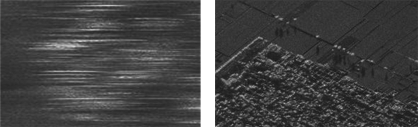
An airborne remote sensing system has advantages in mobility, real-time performance, costs and three-dimensional observation capability, which is widely used in disaster monitoring, military reconnaissance and meteorological observation. However, the remote sensing system requires the airplane to be moving in an ideal way (uniform rectilinear motion), which often cannot be achieved in real applications because of the external environment such as airflow disturbance and internal disturbance such as the vibration of the airplane, resulting in blurring, defocussing, distortion and pixel aliasing that lower the quality of the image (De Macedo et al., Reference De Macedo, Scheiber and Moreira2007; Chen et al., Reference Chen, Wang, Jia and Progri2012). At the beginning of this century, a direct geo-referencing system was proposed to directly measure the position and orientation of the sensor without the use of traditional ground-based measurements (Mostafa and Hutton, Reference Mostafa and Hutton2001). A Position and Orientation System (POS) such as a Global Position System (GPS)/Inertial Navigation System (INS) integrated measurement system, has become indispensable in airborne remote sensing systems because it can provide real-time motion parameters (Fang et al., Reference Fang, Chen and Yao2014). Figure 1 shows the results of an airborne Interferometric Synthetic Aperture Radar (InSAR) without use of a POS and using a POS. The accuracy of the POS will determine the quality of airborne remote sensing images.
Motion compensation for improving the quality of an airborne remote sensing image.

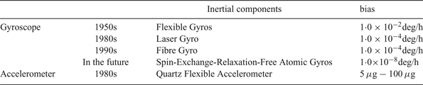
The accuracy of the INS will significantly influence POS accuracy, especially the accuracy of altitude. GPS can only provide position and velocity measurements at a low frequency (1–20 Hz) and the INS is needed to improve the output frequency to meet the payload's demands (200 Hz). Errors in INS can be divided into two basic groups; one is system errors (measurement errors, calibration errors, etc.) and another is modelling errors (model approximation errors, etc.) (Fang and Yang, Reference Fang and Yang2011). The INS system errors mainly depend on gyroscope drift and accelerometer bias. To eliminate these errors, the accuracy of the gyroscopes and accelerometers has been continuously improved. (see Table 1) shows the development of gyroscopes and accelerometers that are usually be used in POS.
Precision of inertial components.

With the improvement of the performance of the inertial components, the model errors have become one of the main error sources of INS. Typically, the gravity used in the INS solution is considered as a “normal” gravity model (World Geodetic System (WGS)-84) (Grejner-Brzezinska and Wang, Reference Grejner-Brzezinska and Wang1998), which leads to gravity disturbance, defined as the difference between “normal” gravity and actual gravity, being incorporated into the system, but not properly allowed for. Gravity disturbance is a vector reflecting the difference between normal gravity and actual gravity in east, west and vertical directions. The United States (US) National Geospatial-Intelligence Agency (NGA) gives statistical results of global gravity disturbance and these show that the maximum and minimum of gravity disturbance is 966·334 mGal and −385·543 mGal (1mGal = 10−5 m/s2), respectively, which is already even larger than accelerometer bias.
There are three major methods to achieve gravity compensation: a gravity sensor, gravity disturbance modelling and the Direct Difference Method (DDM) (Kwon, Reference Kwon2004), However, these methods are proposed for INS but not POS. A gravity sensor normally includes a gravimeter and a gravity gradiometer (Zhao et al., Reference Zhao, Liu and Yuan2009). A gravimeter can only acquire vertical gravitational acceleration and a gravity gradiometer can obtain gravity disturbance after complex mathematical calculations but cannot be applied to real-time gravity compensation (Wang et al., Reference Wang, Wang, Fu, Liu and Lin2016; Li et al., Reference Li, Shao, Paik, Huang, Song and Bian2014). Gravity sensor products are mainly used in static measurement, and to our knowledge, a dynamic gravity sensor has not been reported to date.
The gravity model method is proposed for the optimal theoretical estimation of gravity disturbance. There are generally two kinds of gravity model, the deterministic gravity model and the statistical gravity model. A deterministic model, such as the finite element model or spherical harmonic model, needs complex calculation to obtain gravity disturbance that cannot be used in real-time gravity compensation. A statistical model using large amounts of accurate data of local gravity disturbance (Siouris, Reference Siouris2009) is mainly used for the analysis of gravity data. This gravity model has the latest Gauss Markov model and Auto Regressive (AR) model.
The DDM uses GPS to obtain gravity disturbance and the accuracy is directly determined by GPS (Burton, Reference Burton2000). However, real-time single point GPS can only obtain gravity disturbance to a limited accuracy that cannot satisfy the requirement of real-time gravity compensation.
Motion errors will severely weaken the quality of the remote sensing image, hence precise motion information significantly improves the results of remote sensing processing. Consequently, the ability of a POS to provide motion information is becoming crucial as an important device for remote sensing motion compensation (Nagai et al., Reference Nagai, Chen and Shibasaki2009; Chen and Ma, Reference Chen and Ma2012). However, gravity disturbance is normally ignored in POS solution procedures. For high-precision POS, gravity disturbance is a significant error source with decisive effects on the accuracy of POS. The gravity compensation solution based on the DDM and AR models can substantially improve the horizontal attitude accuracy of POS (Fang et al., Reference Fang, Chen and Yao2014). However, when limited by single point GPS precision, this method is mainly used in post-processing of the images from the remote sensing load, and cannot meet the needs of real-time imaging. Because of this and the disadvantages of those methods, this paper proposes a new method named Gravity-map Modelling Method (GM-M).
The rest of this paper is organised as follows. In Section 2, the error analysis of the POS based on gravity disturbance is carried out to show the significance of gravity compensation. Section 3 introduces a new interpolation method based on Gaussian Process Regression (GPR) to update the gravity map. Section 4 introduces the proposed GM-M in POS gravity compensation. In Section 5, a flight experiment is carried out to evaluate the performance of the proposed method; the result analysis shows the comparison with other methods. Section 6 concludes the work.
2. BASIC ANALYSIS OF GRAVITY COMPENSATION
2.1. Errors of POS based on gravity disturbance
The error analysis is based on the specific equation of INS (Wang, et al., Reference Wang, Xiao, Deng and Fu2014)
 $$V^{n}= f^{n} - (2w^{n}_{en}) \times V^{n} + g^{n}$$
where V n is the velocity of the airplane in the n-frame, f nis the vector of specific force measured by accelerometers in the n-frame,  $\omega_{ie}^{n}$ is the earth rotation vector,
 $\omega_{en}^{n}$ is the angular airplane rate over the ellipsoid and gn is the actual gravity vector.
Generally, in the POS solution, gn is approximately replaced by γ which is normal gravity, the gravity disturbance  $\delta \hbox{g}^{n}$ is usually ignored.
 $$g^{n} = \gamma + \delta g^{n}$$
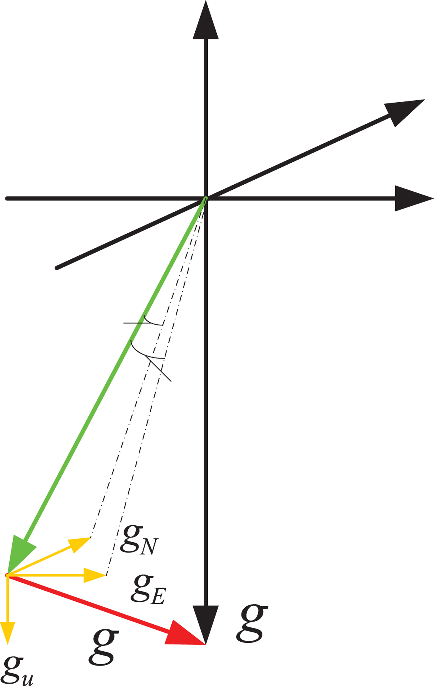
 $\delta \hbox{g}^{n}$ is the difference between actual gravity vector and normal gravity vector. The gravity disturbance can be also expressed as a vertical deflection:
 $$\delta g =[\Delta g_{E}, \Delta g_{N}, \Delta g_{U}] = [- \gamma\eta, \gamma\xi, \Delta g_{U}]$$
where  ${\rm \Delta}\hbox{g}_{E}$,
 ${\Delta}\hbox{g}_{N}$,
 ${\Delta}\hbox{g}_{U}$ are the east, north and vertical gravity disturbances, and are the east and north vertical deflection, as shown in Figure 2.
Gravity disturbance.

The “normal” gravity model regards the Earth as an ellipsoid with invariant mass distribution and it can be calculated using WGS84, which is as follows (DZ-T 0082-2006, 2006):
 $$\eqalign{ \gamma =& 9\cdot78032 \times (1+0\cdot005302\sin^{2} L - 0\cdot0000058\sin^{2} 2L) \cr &-(3\cdot0877 - 0\cdot0044 \sin^{2} L)\times 10^{-6} h + 0\cdot072 \times 10^{-12} h^{2}}$$
where L denotes the geographic latitude and h the altitude.
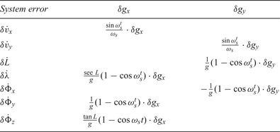
As the gravity disturbance error in a POS works in the same way as the accelerometer bias, it is easy to obtain the influence of gravity disturbance on the POS output from the inertial navigation error equation; the result is shown in Table 2. Table 3 gives the accuracy of POS product POS AV610, which is one of the most advanced POS products in the world. If east and north components of gravity disturbance are assumed as 15 mGal and 17 mGal (1 mGal = 10−5 m/s2), which is derived from an NGA global gravity map for the Beijing district, nearly 8‰ heading error may be caused, that may reach 26·7% of POS AV610 heading absolute accuracy and 2‰ pitch and roll error that may reach 40% of POS AV610 pitch and roll absolute accuracy. This will markedly lower the quality of the airborne remote sensing image. Additionally, the gravity disturbance is usually more than 15 or 17 mGal in real-world applications, so gravity compensation is indispensable in a high-accuracy POS.
The effect of gravity disturbance on POS.

Accuracy of POS AV610.

2.2. GPS accuracy required by gravity compensation
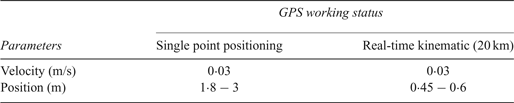
The Direct Difference Method (DDM) is generally adopted for airborne gravity measurement, and its accuracy largely relies on the accuracy of GPS. Nassar (Reference Nassar2003) analysed the accuracy of GPS and concluded that the position accuracy of GPS should be better than 0·1m, and the velocity accuracy should be better than 0·03 m/s to obtain the gravity disturbance at the 1 mGal accuracy level. There are two typical methods for real-time GPS measurements: Single Point Positioning (SPP) and Real-Time Kinematic (RTK). Table 4 shows the accuracy of these operating modes in a NovAtel DL-V3 (NovAtel, 2016). The results demonstrate that SPP GPS cannot meet the demand of real-time gravity disturbance measurement because the position accuracy is inferior to 1·8 m. Although RTK GPS has a higher accuracy in real-time position measurement that performs better than SPP GPS, its position accuracy still cannot reach 0·1 m and its accuracy can only be guaranteed within 20 km of the reference antenna (Wang et al., Reference Wang, Xiao, Deng and Fu2014), which is too small for airborne remote sensing applications. RTK GPS with 0·45 m position accuracy can only obtain gravity disturbance at around the 3 mGal level. Consequently, the real-time GPS technique still cannot reach the accuracy that is required by real-time gravity disturbance measurement in an airborne remote sensing system.
GPS accuracy in different status of NovAtel DL-V3.

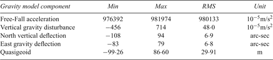
Accuracy of GGMplus.

3. GRAVITY MAP
A gravity map is a type of Earth gravity model constructed by the data from a gravity satellite combined with data from airborne gravitymeasurement and ground measurement, which can provide knowledge of Earth's gravity field structure. There is a strong scientific interest in modelling Earth's gravity field for its variety of applications in climate and sea level change research, surveying and engineering and inertial navigation (Siouris, Reference Siouris2009). Earth Gravity Model (EGM) 96 and EGM 2008 are the most common and advanced gravity maps released by the National Aeronautics and Space Administration (NASA) and NGA in 1996 and 2008 respectively, and their resolution remains limited to spatial scales of mostly 2-10 km globally, which is insufficient for gravity compensation in inertial navigation. With the development of gravity satellites, a new gravity map named GGMplus (Global Gravity Model, with plus indicating the leap in resolution over previous 10 km resolution global gravity models) has been proposed, which is an unprecedented ultra-high resolution Earth gravity field that is a combined solution based on the Gravity Field and Steady-State Ocean Circulation Explorer (GOCE)/Gravity Recovery and Climate Experiment (GRACE) gravity satellite (providing the spatial scale of ~10000 down to ~100 km), EGM2008 (~100 to ~10 km) and topographic gravity (scales of ~10 km to ~250m) (Hirt et al., Reference Hirt, Claessens, Fecher, Kuhn, Pail and Rexer2013). GGMplus can provide gravity disturbance data over all continents at 7·2 arc-seconds (~200 m in a north-south direction) spatial resolution.
An improved gravity map resolution is usually needed when we use it in a relatively small area, because the raw map is globally-based. An interpolation method based on Gaussian Process Regression (GPR) is proposed. The advantage of the proposed method is that it can update the gravity map by adding any local gravity disturbance data, such as DDM or known national data, to further improve the accuracy. The gravity map will be updated after GPR by the integration of original and added data. However, the GPR can also be used without any data added and can still guarantee the accuracy of the gravity map for real-time gravity compensation.
GPR is a new machine learning method in the context of Bayesian and statistical learning theory (Lawrence, Reference Lawrence2005). It provides a flexible framework for probabilistic regression and is widely used to solve high-dimensional, small-sample or nonlinear regression problems (He et al., Reference He, Liu, Zhao and Yang2013). It can accurately forecast new data points based on known data in the gravity map by considering the relationship between them. The principle of GPR follows.
Consider a training set  $D = \lcub \lpar x_{i}\comma \; y_{i}\rpar \vert i= 1\comma \; 2\comma \; \ldots \comma \; n\rcub = \lpar X\comma \; y\rpar $, where x i ∈ R d denotes an input vector of d dimensions and y i ∈ R denotes a corresponding scalar output.
 $X = \lsqb x_{1}\comma \; x_{2}\comma \; \ldots \comma \; x_{n}\rsqb $ denotes an input matrix of dimension d × n. The purpose of GPR is to learn the mapping relationship between inputs X and outputs y, and predict the most possible output value f(x *) of the new test point x *. The implementation of GPR can be divided into prediction and training steps.
3.1. The GPR prediction step
A Gaussian Process (GP) is a collection of random variables that can be completely determined by its mean function and covariance function as: (Lawrence, Reference Lawrence2005)
 $$\left\{{\eqalign{& {m(x) = E[f({x})]} \cr & {k(x,x^{\prime}) = E[(f({x}) - m(x)f(x^{\prime}) - m({x}^{\prime}))]} }} \right.$$
where x, x ′ ∈ R d denotes a random variable. The GP can be defined as  $f\lpar x\rpar \sim GP\lpar m\lpar x\rpar $, k(x, x’)). For the nonlinear regression cases, consider model:
 $$y = f(x) + \varepsilon$$
where x denotes an input vector, f denotes the function value and y is the observed value with noise. We assume that the noise satisfies the distribution  $\varepsilon \sim N\lpar 0\comma \; \sigma^{2}_{n}\rpar $. We can get the prior distribution of observed value y (Park et al., Reference Park, Huang and Ding2011; Petelin et al., Reference Petelin and Kocijan2011)
 $$y \sim N(0, K(X,X)+ \sigma^{2}_{n} I_{n})$$
and the joint prior distribution of observed value y and prediction:
 $$\left[ {\matrix{ y \cr {f_ * } \cr } } \right]N\left( {0,\left[ {\matrix{ {K(X,X) + \sigma _n^2 I_n} & {K(X,x_ * )} \cr {K(x_ * ,X)} & {k(x_ * ,X_ * )} \cr } } \right]} \right)$$
where  $K\lpar X\comma \; X\rpar = K_{n}= \lpar k_{ij}\rpar $ is the n×n symmetric and positive definite covariance matrix and its element
 $k_{ij} = k\lpar x_{i}\comma \; x_{j}\rpar $ measures the relativity between x i and x j.
Then the joint posterior distribution of prediction can be obtained as
 $$f_{\ast} \vert X, y,x_{\ast} \sim N (\bar{f}_{\ast}, \hbox{cov}(f_{\ast}))$$
where
 $$\bar{f}_{\ast}, K(x_{\ast},X)[K(X,X) + \sigma^{2}_{n} I_{n}]^{-1} y$$
 $$\hbox{cov}(f_{\ast}) = k(x_{\ast}, x_{\ast}) - K(x_{\ast}, X) \times [K(X,X) + \sigma^{2}_{n} I_{n}]^{-1} K(X,x_{\ast})$$
3.2. The GPR training step
The GPR can choose various covariance functions. We choose the most common function that is the squared exponential covariance function:
 $$K(x,x') = \sigma^{2}_{f} \exp(\displaystyle{{1}\over{2}}(x-x')^{T} M^{-1}(x-x'))$$
The set of parameters  $\theta = \lcub M\comma \; \sigma^{2}_{f}\comma \; \sigma^{2}_{n}\rcub $ are called hyper-parameters, and can be obtained by the Maximum Likelihood Estimate method. The training step of GPR is to obtain optimal hyper-parameters. We first build the negative log marginal likelihood function and its partial derivatives with respect to the hyper-parameters. Then we minimise the partial derivatives to obtain the optimisation of hyper-parameters based on the conjugate gradient and Newton's method, which is shown as follows (He et al., Reference He, Liu, Zhao and Yang2013):
 $$L(\theta) = \displaystyle{{1}\over{2}} y^{T} C^{-1} y + \displaystyle{{1}\over{2}}\log \vert c \vert + \displaystyle{{n}\over{2}} \log 2\pi$$
 $$\displaystyle{{\partial L(\theta)}\over{\partial \theta_{i}}} = \displaystyle{{1}\over{2}}tr\left((\alpha \alpha^{T} - C^{-1}) \displaystyle{{\partial C}\over{\partial \theta_{i}}}\right)$$
After that, we can compute the variance and mean of prediction point based on the hyper-parameters.
The implementation of the interpolation method based on GPR is as follows:
(1) Download the GGMplus data on (http://grodesy.curtin.edu.au/research/models/GGMplus/).
(2) Replenish local gravity disturbance data to the gravity map (Optional)
(3) Construct training set
(15) $$X = \left[ {\matrix{ {\lambda _1} & {\lambda _2} & \ldots & {\lambda _n} \cr {L_1} & {L_2} & \ldots & {L_n} \cr } } \right]$$(16)where the input vector X denotes the latitude and longitude of the data point and output vector y denotes the corresponding gravity disturbance. If there are any added local gravity data, it will also be put into the training set to update the gravity map.$$y = [\sigma g_{1}\quad \sigma g_{2}\quad \ldots\quad \sigma g_{n}]$$
(4) The GPR prediction step will output the gravity disturbance of the new position point based on the training step. Therefore, an interpolation process is completed to improve the resolution of the gravity map.


Thus, a high-resolution gravity map is established to provide the local gravity disturbance. To meet the real-time requirement of the sensing system, further gravity map processing is required.
4. GRAVITY MAP MODELLING METHOD (GM-M)
4.1. Gravity Model
4.1.1. Gaussian-Markov model
To achieve the real-time requirements of gravity compensation, a gravity model is constructed and introduces a Kalman filter to make a real-time estimation of gravity disturbance. A statistical gravity model takes the form of an Auto Covariance Function (ACF), Power Spectral Densities (PSD) or a linear system of differential equations driven by white noise. There are several benefits of a statistical model and it has received much attention in the last few years. First, more than 80% of the energy of the gravity field is contained in wavelengths that are very short relative to the radius of the earth. Second, statistical gravity models facilitate computational tools, such as the Kalman filter. Gravity modelling is used extensively in modelling of inertial error dynamics for Kalman filter integration.
The Gauss-Markov (GM) model and the Auto-Regressive (AR) model are the most common and developed statistical gravity models. However, there is limited research on gravity compensation using these statistical models. GM modelling is a stationary process that can describe many physical random processes to a good approximation. The AR model is based on the mathematical modelling of a time series of measurements. Although the AR model may construct a more accurate gravity model by appropriate measurements, it can only be applied in a post-process manner since it needs a time series of measurements. However, the GM model also needs a large amount of accurate local gravity disturbance data. As a result, the gravity map constructed before will be used to provide local gravity disturbance data to overcome the difficulty of modelling. The covariance functions of first-order Gauss-Markov model is shown in Equation (17) and PSD is shown in Equation (18).
 $$C_{x}(\tau)= \sigma^{2} e^{\beta \vert\tau \vert}$$
 $$\Phi_{x}(\omega)= \displaystyle{{2\sigma^{2}\beta}\over{\omega^{2}} + \beta^{2}}$$
where σ is the mean square deviation of state variable and β is the reciprocal of correlation time  $\lpar \beta = \displaystyle{{1}\over{\tau_{g}}}\rpar $.
Using a first order GM model, the gravity disturbance is defined by the following first-order differential equation:
 $$\dot{\delta} g(t) = -\beta\delta g(t) + \sqrt{2\beta \sigma^{2} w(t)}$$
The discrete form of the above equation is included inside the error model of the inertial system using the difference equation:
 $${\delta} g_{k+1} = (1-\beta\Delta t)\delta g_{k} + \sqrt{2\beta \sigma^{2} \Delta tw_{k}}$$
where Δ t is the sampling period of the system and depends on the POS product data sampling period. In the experiment, the sampling rate of the POS products is 200 Hz.
4.1.2. Parameter update of the GM model
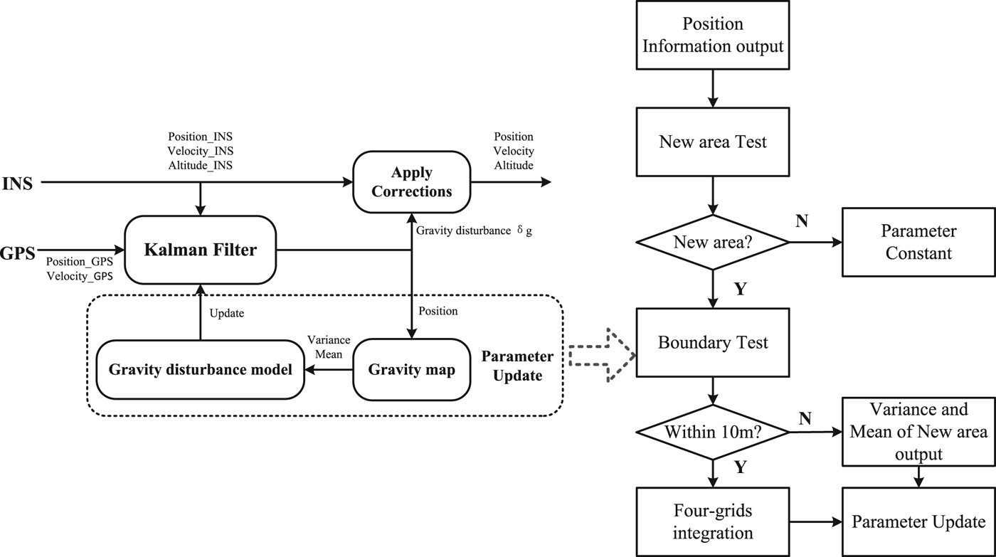
Using the same gravity model in the whole compensation process obviously cannot reflect actual gravity disturbance. Therefore, a time-varying GM model is proposed. The parameters of the model will change in different areas of the gravity map. Most present INS model the gravity disturbance as a first order GM model with a large correlation time. The gravity disturbance vector  $\delta g = \lsqb \Delta g_{E}\comma \; \Delta g_{N}\comma \; \Delta g_{U}\rsqb $ will be estimated respectively through three independent Markov models in Kalman filters. When the airplane moves to a new area, the parameter σ will be updated by the variance of that area from the gravity map and w(t) will be considered as a random noise with the mean of that area from the gravity map.
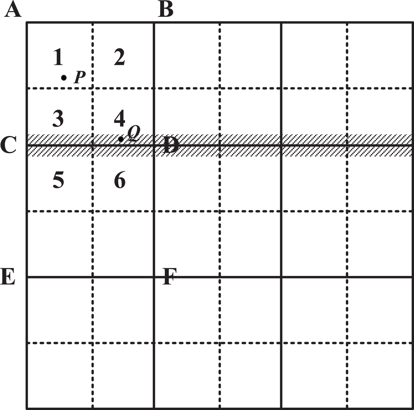
The gravity map will be divided into several areas before the take-off and the variance and mean of every area will be calculated to update σ and w(t) of the GM model. The velocity of the airplane determines the size of the area. According to the velocity of our experiment airplane, we divided the gravity map into 500 × 500 m segments, as shown in Figure 3. The squares ABCD and CDEF are of 500 × 500 m area, and its variance and mean will be calculated before flying. The parameter of the GM model will change due to the position information output by the POS, as shown in Figure 3. When the airplane moves from outside of area ABCD to point P, the parameters of the GM model will update according to the variance and mean of area ABCD. Thus, the judgment of the change of GM model is whether the airplane moves to another area in the gravity map. However, because the output of the POS includes position error that is in the order of 1–5 m, it is hard to determine if the point is in ABCD or CDEF when the airplane moves to the edge of the area such as point Q. Therefore, a four-grid integration method is proposed. Each area will be divided into four small squares such as squares 1, 2, 3 and 4 of ABCD, and the variance and mean of squares 1, 2, 3, 4 will be also calculated. Because the numbers of data are all the same in squares 1, 2, 3, 4, it is easy to get the variance and mean of any square constructed by four small squares. When the airplane moves to point Q, the small squares 3, 4, 5, 6 will be integrated to a new area to provide parameters to the GM model. Therefore, a time-varying GM model will be constructed to accurately reflect the change of gravity disturbance. The model can change according to its position based on the gravity map.
Diagram of gravity map.

The block diagram of GM-M is shown in Figure 4, where the parameter update process is shown in the right of picture. The detailed design of the Kalman filter will be introduced next.
Block diagram of GM-M and parameter update.

4.2. Kalman Filter
The time-varying-GM model will be introduced into the error equation of the POS to estimate gravity disturbance using a Kalman filter. The system state equation and observation equation in the Kalman filter is as follows:
 $$\dot{X} = F \cdot X + G \cdot w$$
 $$Z = H \cdot X+ V$$
where  $X = {\rm [}\sigma P\quad \sigma v\quad \theta \quad \varepsilon \quad {\rm \bigtriangledown }\sigma g{\rm ]}^T$ is the system state vector, including three position errors, three velocity errors, three altitude errors, three gyroscope drift errors, three accelerometer zero bias errors and three gravity disturbance errors. F and G are the state transition matrix and distribution matrix of the system noise and its specific form follows:
 $$F_{18 \times 18} = \left[ {\matrix{ {F_1} & {0_{15 \times 3}} \cr {0_{3 \times 15}} & {F_2} \cr } } \right]$$
 $$G_{18 \times 18} = \left[ {\matrix{ {G_1} & {0_{15 \times 3}} \cr {0_{3 \times 15}} & {G_2} \cr } } \right]$$
F 1 and G 1 are defined in (Nassar, Reference Nassar2003)
 $$F_1\left[ {\matrix{ { - \beta _1} & 0 & 0 \cr 0 & { - \beta _2} & 0 \cr 0 & 0 & { - \beta _3} \cr } } \right]$$
 $$G_1\left[ {\matrix{ 1 & 0 & 0 \cr 0 & 1 & 0 \cr 0 & 0 & 1 \cr } } \right]$$
w denotes the system noise vector, whose components are considered as zero-mean random white noise. Z is the observation vector, which is the difference of position, velocity and acceleration, which is different from the traditional Kalman filter that represents gravity disturbance, between the INS and GPS:
 $$Z = \left[ {\matrix{ {X_{INS} - X_{GPS}} \cr {V_{INS} - V_{GPS}} \cr {f^n + g^n - (2w_{ie}^n + \omega _{en}^n ) \times V_{GPS}^n - \tilde V_{GPS}^n }}} \right]_{9 \times 9}$$
H is the observation matrix which is defined as follows:
 $$H = \left[ {\matrix{ {I_{6 \times 6}} & {0_{6 \times 12}} & {} & {} & {} \cr {0_{3 \times 6}} & {H_1} & { - C_b^n } & {0_{3 \times 3}} & {H_2}}} \right]$$
 $$H_1 = \left[ {\matrix{ 0 & {f_2} & { - f_y} \cr { - f_z} & 0 & {f_x} \cr {f_y} & { - f_x} & 0 \cr } } \right]$$
 $$H_2 = \left[ {\matrix{ {1 - \beta _1\Delta t} & {} & {} \cr {} & {1 - \beta _2\Delta t} & {} \cr {} & {} & {1 - \beta _3\Delta t} \cr } } \right]$$
where  $\beta_{1}\comma \; \beta_{2}$ and β3 depend on the obtained gravity disturbance model. As a result, H 2 is time-varying. V is the observation noise vector which is also considered as zero-mean random white noise.
The gravity disturbance estimate by the Kalman filter can be used to compensate gravity in the INS according to Equation (1). Because there is not a standard gravity disturbance, the performance of the proposed method will be evaluated by the influence on the accuracy of the POS.
5. EXPERIMENTS AND RESULTS DISCUSSION
A flight experiment was carried out on 12 December 2015, in YanLiang, China, to evaluate the performance of the proposed GM-M in a POS application. The experiment was conducted by BeiHang University.
5.1. Experiment equipment
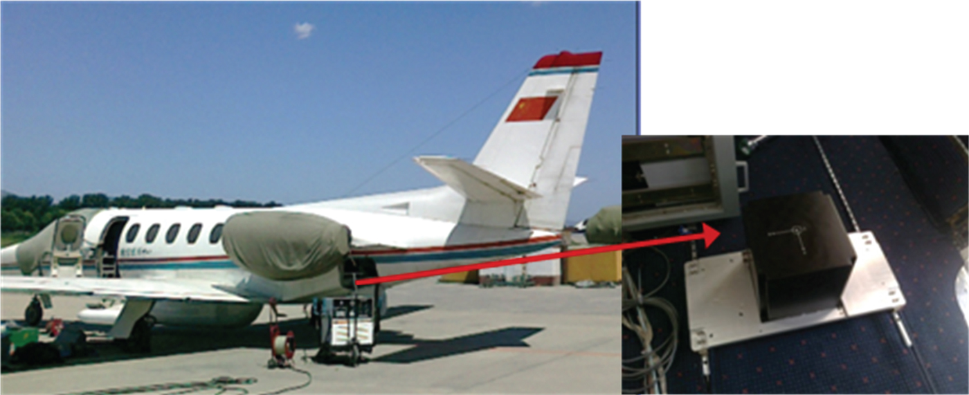
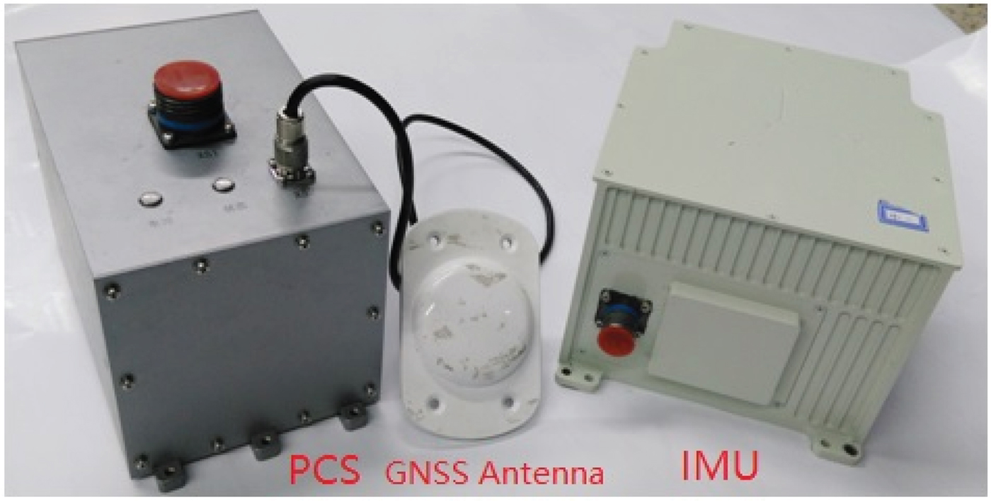
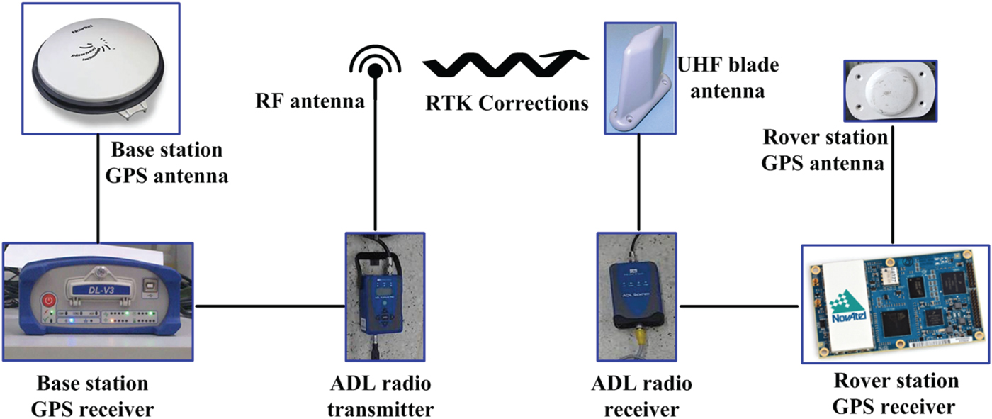
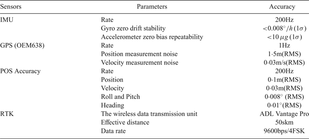
The aircraft used was a Yun 7 (Figure 5). The POS for the flight experiment used a high-precision Fibre Optic POS (TX-R610) developed by BeiHang University, and the specifications are shown in Table 6 and Figure 6. To obtain differential GPS data, a NovAtel DL-V3 GPS receiver as ground station was placed near the centre of the mapping area. RTK Corrections can be transmitted from the ground station to the rover station to improve position accuracy (see Figure 7). The base station is the Global Navigation Satellite System (GNSS) receiver which is acting as the stationary reference. In most cases, a data link is provided between the base station and rover station (two NovAtel receivers) in order to receive corrections.
Yun 7 airplane and high accuracy POS.

High precision TX-R610 POS products.

Yun 7 airplane and high accuracy POS.

TX-R610POS product performance list.

5.2. The flight experiment plan
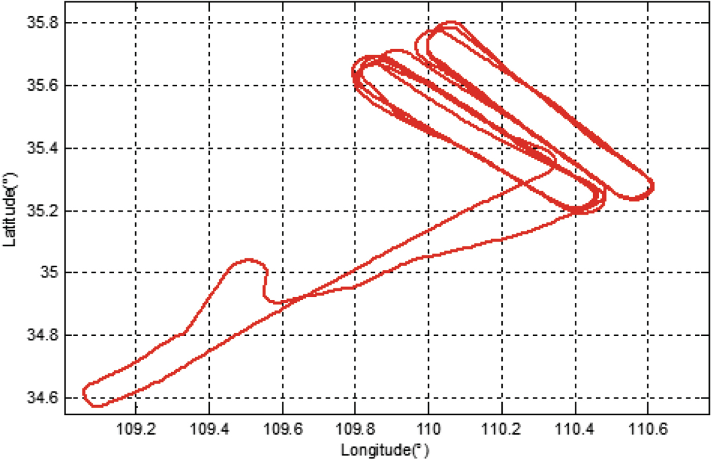
The whole experiment lasted for two hours, and the flight route is shown in Figure 8. The experiment data was selected from an experiment area that did not include take-off or landing. To analyse the performance of the proposed gravity compensation method, we select part of the route where the airplane moves smoothly.
Trajectory of flight experiment.

5.3. Data Analysis and Results
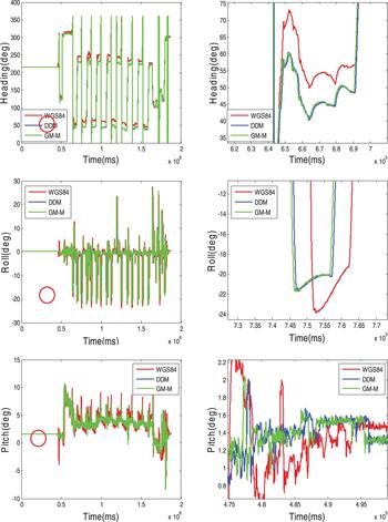
Three real-time gravity compensation methods are compared in this part. These are the normal gravity model (WGS84), DDM (RTK GPS) and the proposed GM-M method. The left panels of Figure 10 show the heading, pitch and roll of the POS using three different gravity compensation methods and the right panels of Figure 10 show a partial enlarged section of heading, roll and pitch data.
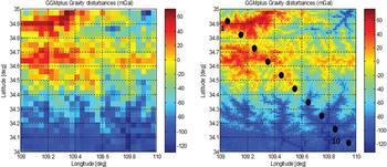
Gravity map.

Attitude error in POS using WGS84, DDM and GM-M.

5.3.1. Accuracy assessment of gravity map
Because there is no standard of gravity disturbance, the gravity disturbance obtained by DDM with post-processing differential GPS was carried out as a baseline of gravity disturbance to compare with the gravity disturbance from the gravity map since post-processing differential GPS can reach 0·1 m position accuracy. The original gravity map and interpolation result is shown in Figure 9, and Table 7 shows ten selected points to compare these two methods. The ten points selected are shown in Figure 9 and were selected randomly from the flight test trajectory shown in Figure 8. The results showed that the gravity disturbance from the gravity map could reach the same level as DDM (post-processing). The maximum difference between the gravity disturbance of DDM and the gravity map is 1·45 mGal and the minimum is 0·36 mGal. Although there are still errors in DDM with post-processing GPS, the error should be lower than 1 mGal. As a result, the accuracy of the gravity map can be proven to be at the same level as DDM with post-processing differential GPS.
Comparison of DDM and gravity map.

5.3.2. Accuracy assessment of GM-M
To evaluate the performance of the proposed GG-M, the results of three real-time gravity compensation methods, GM-M, DDM (RTK GPS) and WGS84 are given.
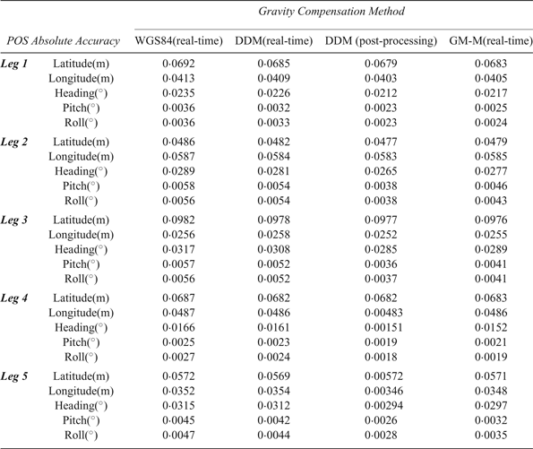
The method of gravity compensation is evaluated from five indices: latitude, longitude, heading, pitch and roll. The experimental results are shown in Table 8 which selects five level flight sections to evaluate the performance of proposed GM-M method. The experimental results are analysed as follows:
(1) From the experimental results of WGS84 and DDM (real-time) methods, it can be seen that the two methods have little difference in accuracy, so the DDM (real-time) method is not suitable for real-time gravity compensation, which is consistent with the analysis at the beginning of this paper.
(2) From the experimental results of the WGS84 and GM-M methods, it can be seen that the heading, pitch and roll accuracy of the GM-M method is obviously better than that of WGS84. From leg 1 to leg 5, GM-M performs better than WGS84. Taking leg 3 as an example, the pitch and roll error of the GM-M is nearly 0·002°, which is an 0·0016° and 0·001° (28·1% and 17·3% increments, respectively) improvement compared with WGS84, and the heading error of the proposed method is 0·0289°, which is an improvement of 0·0028° and 0·0019° (8·8% and 6.2% increments, respectively) compared with WGS84.
(3) From the experimental results of GM-M and DDM (post-processing) methods, it can be seen that the heading, pitch and roll accuracy of the GM-M method is same as that of DDM (post-processing).
(4) From the experimental results of WGS84, DDM (real-time) and GM-M methods, it can be seen that there is not much difference in position accuracy among the three real-time gravity compensation methods. Therefore, the gravity disturbance has little influence on the position accuracy of a POS.
Comparison of experimental results of different gravity compensation methods.

6. CONCLUSION
With the continuous development of inertial sensors, Gravity disturbance has become the main error source of a POS that will reduce the imaging quality of an airborne remote sensing system. An accurate real-time gravity compensation method is proposed which constructs a time-varying GM model for gravity disturbance and uses a Kalman filter to estimate optimal gravity disturbance. A gravity map is used to provide local gravity disturbance for modelling and an interpolation method based on GPR is proposed to enhance its resolution. The performance of the proposed method has been verified in a flight experiment. The result shows that GM-M can improve the attitude accuracy of a POS and performs better in resisting GPS errors compared with other real-time gravity compensation methods. In the future, the accuracy of GM-M will be further improved with the development of gravity satellites and improvements of gravity maps.
ACKNOWLEDGMENTS
This work was supported by the National Nature Science Foundation of China (Grants 61573040, 61421063, 61571030, 61473020, 61661136007) and the National High Technology Research and Development Program of China (863 Program) (Grants 2015AA124001, 2015AA124002) and The Ministry of Science And Technology Major Special Instruments of China (Grant 2012YQ160185) and Beijing Science And Technology Plan under Grant (D161100005816001, D171100006217003).