1. Introduction
Traditional industrial robots perform operational tasks in a specific environment using “teaching/playback.” However, developments in robotics have led to a gradual expansion of the field from traditional fixed-point tasks to autonomous operations in unstructured environments, such as deep-sea exploration and salvage [Reference Kelasidi, Liljebäck, Pettersen and Gravdahl1, Reference Yamada and Hirose2], space shuttle inspection and maintenance [Reference Gao, Wang, Niu, Wang and Zheng3], nuclear reactor failure detection [Reference Buckingham and Graham4, Reference Bogue5], and in vivo testing [Reference Hu, Wang, Zhao, Li and Sun6] in medicine and healthcare. Traditional robots struggle to meet the demands of the above applications due to their mechanical structure [Reference Zhao7, Reference Liu, Jin and Gao8], workspace [Reference Bai9], and flexibility [Reference Zhang, Qiu and Dai10–Reference Hamidi, Almubarak and Tadesse12]. Scholars have been inspired by physiology [Reference Salomon and Wolf13, Reference Xie, Zhu, Shen and Ren14] and the motion mechanics [Reference Komura, Yamada and Hirose15] of natural organisms which, when applied to the study of HRETR, offer excellent operational performance and motion flexibility, enabling operation in complex environments. HRETRs are a form of a complex redundant mechanical system. Displacement analysis for HRETRs is a challenging problem due to their coupling structure, complex mathematical model, and the cost of calculations. Therefore, providing an inverse displacement algorithm with multiple solutions is of particular importance for the development of HRETR.
Some works have been done on the inverse kinematics of robots with redundant degrees of freedom (DOFs) robots. For traditional redundant robots, numerical iterative methods based on the Jacobian matrix and associated deformations [Reference Aristidou and Lasenby16, Reference Tchoń and Janiak17] are typically used to solve the inverse kinematics problem, such as the Jacobian pseudo-inverse [Reference Tchoń and Janiak17], Jacobian transpose [Reference Moosavian and Papadopoulos18], singular value decomposition (SVD) [Reference Colomé and Torras19, Reference Xu, Zhang, Liang and Li20], and damped least squares (DLS) [Reference Wampler21]. Although such methods can obtain the robot’s smooth motion and stable posture, the process of calculation is complicated and time-consuming due to their large matrix operations. Chirikjian and Burdick [Reference Chirikjian and Burdick22, Reference Chirikjian and Burdick23] proposed a modal approach based on the hyper-redundant manipulator’s overall geometrical characteristics, which abstracted the backbone curve into a continuous, smooth spatial curve, and used the curve fitting to obtain the inverse kinematics solutions. Kim and Chirikjian [Reference Kim and Chirikjian24] put forward two solutions for the inverse kinematics of a six DOFs robot based on biopolymer segments. One is the extended elimination method [Reference Kohli and Osvatic25], which can act on the biopolymer segment directly, the other is a heuristic algorithm based on the Lie group theory. In the second method, all the requirements can be met by solving the Jacobian matrix inverse iteration, as verified by numerical examples. Focusing on a hyper-redundant elephant’s trunk robot (HRETR) consisting of six 3UPS-PRU parallel models in series, Zhao et al. [Reference Zhao, Jin, Zhang and Li26] solved the inverse kinematics problem by using a parametric backbone curve to describe the geometric characteristics of the HRETR, but with a lengthy search time. Wang and Chen [Reference Wang and Chen27] proposed a combined optimization method for inverse kinematics, which is efficient and insensitive to the manipulator’s initial and singular configurations, but motion discontinuity can sometimes occur. Tao et al. [Reference Xiong, Tao and Liu28] proposed a modified inverse algorithm for improved tip following motion, to solve the problems of large computation complexity, exceeding joint limits, and large configuration deviations in a hyper-redundant snake-arm robot. Results show that the improved algorithm can guarantee the bending angles and do not exceed the given range at a reduced computational cost. Aristidou and Lasenby [Reference Aristidou and Lasenby29, Reference Aristidou, Chrysanthou and Lasenby30] proposed an algorithm named forward and backward reaching inverse kinematics to solve the anthropometric robot’s inverse kinematics problem, which is efficient, simplicity, convergence speed, and with a controlled performance. Anandhanarayanan and Ordóñez [Reference Ananthanarayanan and Ordóñez31] introduced an efficient method of solving inverse kinematics for 2n+1 DOFs (where n is the number of joints). This method combines an iterative algorithm and a numerical method, based on the Jacobian matrix, to enhance computational efficiency. It is demonstrated with examples of obstacle avoidance and joint limit avoidance. Neppalli et al. [Reference Neppalli, Csencsits, Jones and Walker32, Reference Neppalli, Csencsits, Jones and Walker33] proposed a novel, analytical approach to solve inverse kinematics for multisection continuum robots, implemented these algorithms in the simulation and on a prototype of continuum robot and discussed its possible applications. Kaganov and Karpenko [Reference Kaganov and Karpenko34] introduced an automatic control system to control each section of the manipulator and the entire structure for the multisection trunk type manipulator, and this system can be used to react to changing uncertain conditions in real time. Manfred Husty et al. [Reference Husty, Birlescu, Tucan, Vaida and Pisla35] presented a new algebraic parameterization method to achieve a direct mathematical description between the desired motion parameters of parallel mechanisms and numerical examples for the forward and inverse kinematics were given. Saglia et al. [Reference Saglia, Dai and Caldwell36] investigated a parallel mechanism with a central strut and demonstrated the advantage of introducing the actuation redundancy to eliminate singularities and to improve desterity. Gan et al. [Reference Gan, Dai, Dias and Seneviratne37] presented a kinematics model for linear-actuated symmetrical spherical parallel manipulators (LASSPMs) which had advantages in solving the forward kinematic equations. Zhao et al. [Reference Zhao, Song, Zhang and Lu38] had made some research about HRETR. The HRETR is a form of a complex redundant mechanical system, in which the joint space dimensions are much larger than the dimensions of the operation space in mathematics. As a result, multiple solutions exist for the inverse kinematics of an HRETR, and inverse displacement is a challenging problem. This paper proposes an iterative algorithm, which transforming the HRETR’s inverse displacement into the inverse displacement of parallel modules to solve the complex inverse displacement problem.
This paper’s structure is as follows: Section 2 presents the mechanical configuration of an HRETR and describes the structure. In Section 3, a kinematics model of the HRETR is established and an iterative algorithm for HRETR’s inverse displacement is introduced by considering the joint constraints. Section 4 provides a numerical example. Finally, the conclusions are presented in Section 5.
2. System description
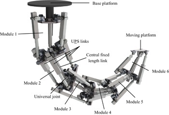
The mechanical configuration of an HRETR is shown in Fig. 1. The HRETR discussed in this paper is composed of six parallel modules with two degrees of rotational freedom. Each parallel module is composed of a base platform, moving platform, central fixed-length link, and three UPS chains in which U is the universal joint, P is the active prismatic joint, and S is the spherical joint. The first parallel module’s central fixed-length link is connected to its own base platform vertically and fixedly and connected to the moving platform through the universal joint. The base platform of the first parallel module is the base platform for the whole HRETR. The first parallel module’s moving platform is the base platform of the second parallel module, and the following parallel modules are connected as before. The moving platform of the last parallel module is the moving platform of the whole HRETR. The HRETR has 18 driving DOFs, and the flexible movement of the end moving platform in 3D space can be realized by coordinating and controlling each driving chain.
Hyper-redundant elephant’s trunk robot (HRETR).

3. Inverse displacement model of HRETR
3.1. Inverse displacement of the parallel module
The inverse displacement model is established according to the
 $k-\mathrm{th}$
parallel module. The following coordinate systems are defined for the inverse displacement model: The reference coordinate system
 $O_{k-1}-x_{k-1}y_{k-1}z_{k-1}$
is attached to the center of the base platform
 $O_{k-1}$
, and the moving coordinate system
 $O_{k}-x_{k}y_{k}z_{k}$
is located at the center of mass of the moving platform
 $O_{k}$
. A rotation matrix
 ${_{}^{Ok-_{1}}}{\boldsymbol{R}}{_{Ok}^{}}$
can describe the orientation of the moving platform. Thus, the rotation matrix can be obtained by:
 \begin{equation} {_{}^{Ok-_{1}}}{{\boldsymbol{R}}}{_{Ok}^{}}=\mathrm{Rot}(\mathrm{z}_{k-1},\varphi _{zk})\mathrm{Rot}(y'_{\!\!k-1},\varphi _{yk})\mathrm{Rot}(x''_{\!\!\!k-1},\varphi _{xk}) \end{equation}
The transformation matrix
 ${_{k}^{k-1}}{{\boldsymbol{T}}}{}$
, which represents the position and orientation of the moving platform for the base platform of the
 $k-\mathrm{th}$
parallel module, can be expressed as:
 \begin{equation} {_{k}^{k-1}}{{\boldsymbol{T}}}{}=\left[\begin{array}{l@{\quad}l} \begin{array}{l} {_{}^{Ok-_{1}}}{{\boldsymbol{R}}}{_{Ok}^{}}\\[5pt] 0 \end{array} & \begin{array}{l} {\boldsymbol{r}}_{k}\\[5pt] 1 \end{array} \end{array}\right] \end{equation}
where
 ${\boldsymbol{r}}_{k}$
donates the position vector of the
 $k-\mathrm{th}$
central link. Hence, the overall forward kinematics model of the HRETR can be obtained by multiplying the homogeneous transformation matrices as:
 \begin{equation} {_{k}^{0}}{{\boldsymbol{T}}}{}={_{1}^{0}}{{\boldsymbol{T}}}{}{_{2}^{1}}{{\boldsymbol{T}}}{}\cdots {_{k-1}^{k-2}}{{\boldsymbol{T}}}{}{_{i}^{k-1}}{{\boldsymbol{T}}}{} \end{equation}
where
 ${_{k}^{0}}{{\boldsymbol{T}}}{}$
is the homogeneous transformation matrix of the
 $k-\mathrm{th}$
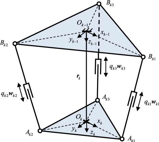
moving coordinate system for the referenced coordinate system fixed on the base platform of the HRETR. The schematic diagram of the parallel module is shown in Fig. 2.
Schematic diagram of parallel module.

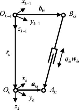
As shown in Fig. 3,
 ${\boldsymbol{a}}_{ki}$
and
 ${\boldsymbol{b}}_{ki}$
denote the position vector of the
 $i-\mathrm{th}$
connection point with the moving platform and the base platform of the
 $k-\mathrm{th}$
parallel module, respectively. The position equation associated with the
 $i-\mathrm{th}$
kinematics chain of the
 $k-\mathrm{th}$
parallel module can be described as:
Vector diagram of a kinematics chain.

 \begin{equation} {\boldsymbol{r}}_{k}+{\boldsymbol{a}}_{ki}={\boldsymbol{b}}_{ki}+q_{ki}{\boldsymbol{w}}_{ki} \end{equation}
where
 $k=1,2,3,\cdots,6, i=1,2,3$
.
The length associated with the
 $i-\mathrm{th}$
kinematics chain of the
 $k-\mathrm{th}$
parallel module can be written as:
 \begin{equation} q_{ki}=\left|\left|{\boldsymbol{r}}_{k}+{\boldsymbol{a}}_{ki}-{\boldsymbol{b}}_{ki}\right|\right| \end{equation}
Furthermore, the position vector
 ${\boldsymbol{r}}_{k}$
can be obtained by the following inverse displacement algorithm.
3.2. Inverse displacement algorithm of HRETR
3.2.1 Algorithm description
Each of the HRETR’s parallel modules is abstracted as a geometric line segment and point model in the inverse displacement algorithm. The algorithm can be divided into forward iterations and backward iterations according to the forward approximation and inverse pose adjustment principle. The position vector
 ${\boldsymbol{r}}_{k}$
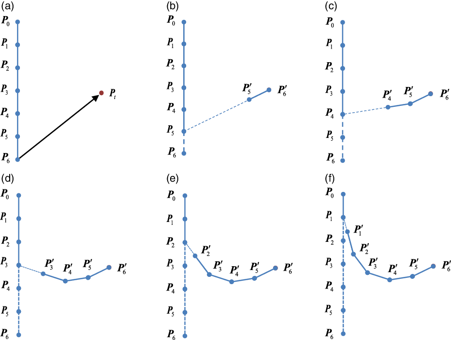
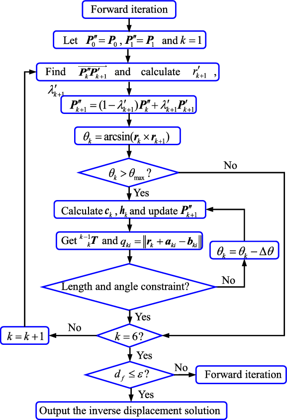
of the central link can be obtained by the following algorithm and the inverse displacement of the HRETR can be solved. In order to describe the position change process clearly, the UPS links are omitted. The forward iteration diagram and the flow chart are presented in Figs. 4 and 5.
Forward iteration. (a) Move the moving platform
 ${\boldsymbol{P}}_{6}$
to the target point
 ${\boldsymbol{P}}_{t}$
. (b) Find the joint
 ${\boldsymbol{P}}'_{\!\!5}$
which lies on the line
 $\overline{\overline{{{\boldsymbol{P}}_{5}{\boldsymbol{P}}'_{\!\!6}}}}$
. (c) Find the joint
 ${\boldsymbol{P}}'_{\!\!4}$
which lies on the line
 $\overline{\overline{{{\boldsymbol{P}}_{4}{\boldsymbol{P}}'_{\!\!5}}}}$
. (d) Find the joint
 ${\boldsymbol{P}}'_{\!\!3}$
which lies on the line
 $\overline{\overline{{{\boldsymbol{P}}_{3}{\boldsymbol{P}}'_{\!\!4}}}}$
. (e) Find the joint
 ${\boldsymbol{P}}'_{\!\!2}$
which lies on the line
 $\overline{\overline{{{\boldsymbol{P}}_{2}{\boldsymbol{P}}'_{\!\!3}}}}$
. (f) Find the joint
 ${\boldsymbol{P}}'_{\!\!1}$
which lies on the line
 $\overline{\overline{{{\boldsymbol{P}}_{1}{\boldsymbol{P}}'_{\!\!2}}}}$
.

Forward iteration flow chart.

Assuming that the initial configuration of the HRETR is at downward, as shown in Fig. 4(a),
 ${\boldsymbol{P}}_{0},{\boldsymbol{P}}_{1}\cdots \cdots {\boldsymbol{P}}_{6}$
denote the position coordinate of each of the robot’s joint points:
 ${\boldsymbol{P}}_{0}$
is the position of the center of the base platform in the first parallel module,
 ${\boldsymbol{P}}_{k}$
and
 ${\boldsymbol{P}}_{k-1}$
are the position of the center of the moving platform and base platform of the
 $k-\mathrm{th}$
parallel module, respectively, and
 $d_{k}$
is the central fixed-length link of the
 $k-\mathrm{th}$
parallel module, as
 $d_{k}=\left|\left|{\boldsymbol{P}}_{k}-{\boldsymbol{P}}_{k-1}\right|\right|$
. All central fixed-length links mentioned in this paper are of identical length
 $d$
.
 ${\boldsymbol{P}}_{t}$
is the target point and
 ${\boldsymbol{r}}_{7}$
denotes the normal vector of the end platform. Since the central fixed-length link of the first parallel module is connected to its own base platform vertically and fixedly, thus,
 ${\boldsymbol{P}}_{0}$
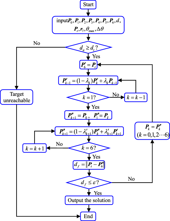
is not involved in the iterative process. The forward iteration determines whether the target point is within the maximum range that the robot can initially reach. The judgment method is as follows:
 \begin{equation} d_{a}={\sum }_{k=1}^{5}d_{k} \end{equation}
 \begin{equation} d_{t}=\left|\left|{\boldsymbol{P}}_{t}-{\boldsymbol{P}}_{1}\right|\right| \end{equation}
where
 $d_{a}$
denotes the total length of the central fixed-length links of the last five parallel modules of the robot,
 $d_{t}$
denotes the distance between the center of mass of the moving platform and the target point in the first parallel module. If
 $d_{a}\lt d_{t}$
, the target point is not within the maximum range that the robot can reach. Otherwise, the target point is within the maximum range that the robot can reach.
The position error
 $\varepsilon$
is given, and then
 $d_{f}$
denoting the distance between the end of the robot
 ${\boldsymbol{P}}''_{\!\!\!6}$
and the target point
 ${\boldsymbol{P}}_{t}$
is computed by
 $d_{f}=\left|\left|{\boldsymbol{P}}_{t}-{\boldsymbol{P}}_{6}\right|\right|$
. If
 $d_{f}\gt \varepsilon$
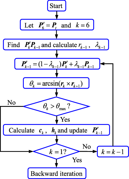
, then start the forward iteration process is started. Otherwise, the iterative calculation will stop. The forward iteration process is as follows:
 ${\boldsymbol{P}}'_{\!\!0},{\boldsymbol{P}}'_{\!\!1}\cdots \cdots {\boldsymbol{P}}'_{\!\!6}$
is the position of each point after forward iteration. Moving the end point of the robot to the target point is the first step, as shown in Fig. 4(b), namely
 ${\boldsymbol{P}}'_{\!\!6}={\boldsymbol{P}}_{t}$
. The second step is finding the line
 ${\boldsymbol{P}}'_{\!\!6}{\boldsymbol{P}}_{5}$
as shown in Fig. 4(c), and then calculating the length
 $r_{5}$
of the link
 ${\boldsymbol{P}}'_{\!\!6}{\boldsymbol{P}}_{5}$
with Eq. (8) and the ratio of
 $d_{5}$
to
 $r_{5}$
with Eq. (9). Substituting
 $r_{5}$
and
 $\lambda _{5}$
into Eq. (10) and obtaining the coordinate
 ${\boldsymbol{P}}'_{\!\!5}$
after updating the position is the third step. By repeating the above calculation process,
 ${\boldsymbol{P}}'_{\!\!4}, {\boldsymbol{P}}'_{\!\!3}, {\boldsymbol{P}}'_{\!\!2}, {\boldsymbol{P}}'_{\!\!1}$
can be obtained.
 ${\boldsymbol{P}}_{0}$
is not involved in the iterative process, let
 ${\boldsymbol{P}}'_{\!\!0}={\boldsymbol{P}}_{0}$
. Thus, the forward iteration is complete:
 \begin{equation} r_{k-1}=\left|\left|{\boldsymbol{P}}'_{\!\!\!k}-{\boldsymbol{P}}_{k-1}\right|\right| \end{equation}
 \begin{equation} \lambda _{k-1}=d_{k-1}/r_{k-1} \end{equation}
 \begin{equation} {\boldsymbol{P}}'_{\!\!\!k-1}=(1-\lambda _{k-1}){\boldsymbol{P}}'_{\!\!\!k}+\lambda _{k-1}{\boldsymbol{P}}_{k-1} \end{equation}
The end platform’s mass center
 ${\boldsymbol{P}}'_{\!\!6}$
coincides with the target point
 ${\boldsymbol{P}}_{\!t}$
after the forward iteration, but the first parallel module’s base platform’s mass center no longer coincides with
 ${\boldsymbol{P}}_{0}$
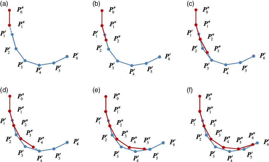
. Therefore, backward iteration is needed to ensure the first parallel module’s moving platform mass center is permanently fixed. Backward iteration is shown in Fig. 6.
Backward iteration. (a) The configuration of the HRETR after forward iteration and
 ${\boldsymbol{P}}'_{\!\!\boldsymbol{1}}$
is covered by
 ${\boldsymbol{P}}''_{\!\!\!1}$
. (b) Find the joint
 ${\boldsymbol{P}}''_{\!\!\!2}$
which lies on the line
 $\overline{\overline{{{\boldsymbol{P}}''_{\!\!\!1}{\boldsymbol{P}}'_{\!\!2}}}}$
. (c) Find the joint
 ${\boldsymbol{P}}''_{\!\!\!3}$
which lies on the line
 $\overline{\overline{{{\boldsymbol{P}}''_{\!\!\!2}{\boldsymbol{P}}''_{\!\!\!3}}}}$
. (d) Find the joint
 ${\boldsymbol{P}}''_{\!\!\!4}$
which lies on the line
 $\overline{\overline{{{\boldsymbol{P}}''_{\!\!\!3}{\boldsymbol{P}}'_{\!\!4}}}}$
. (e) Find the joint
 ${\boldsymbol{P}}''_{\!\!\!5}$
which lies on the line
 $\overline{\overline{{{\boldsymbol{P}}''_{\!\!\!4}{\boldsymbol{P}}'_{\!\!5}}}}$
. (f) Find the moving platform
 ${\boldsymbol{P}}''_{\!\!\!6}$
which lies on the line
 $\overline{\overline{{{\boldsymbol{P}}''_{\!\!\!5}{\boldsymbol{P}}'_{\!\!6}}}}$
.

As shown in Fig. 6(a), the first step of backward iteration is to find the joint
 ${\boldsymbol{P}}''_{\!\!\!1}$
by moving
 ${\boldsymbol{P}}'_{\!\!1}$
to the initial point
 ${\boldsymbol{P}}_{1}$
:
 \begin{equation} r'_{\!\!k+1}=\left|\left|{\boldsymbol{P}}'_{\!\!k+1}-{\boldsymbol{P}}''_{\!\!\!k}\right|\right| \end{equation}
 \begin{equation} \lambda '_{\!\!k+1}=d_{k+1}/r'_{\!\!k+1} \end{equation}
 \begin{equation} {\boldsymbol{P}}''_{\!\!\!k+1}=(1-\lambda '_{\!\!k+1}){\boldsymbol{P}}''_{\!\!\!k}+\lambda '_{\!\!k+1}{\boldsymbol{P}}'_{\!\!k+1} \end{equation}
Then, connect
 ${\boldsymbol{P}}''_{\!\!\!1}$
and
 ${\boldsymbol{P}}'_{\!\!2}$
, calculate the distance
 $r'_{\!\!2}$
between the two points and the ratio
 $\lambda '_{\!\!2}$
of
 $d$
to
 $r'_{\!\!2}$
via Eqs. (11) and (12), and obtain the
 ${\boldsymbol{P}}''_{\!\!\!2}$
via Eq. (13).
 ${\boldsymbol{P}}''_{\!\!\!3}, {\boldsymbol{P}}''_{\!\!\!4}, {\boldsymbol{P}}''_{\!\!\!5}, {\boldsymbol{P}}''_{\!\!\!6}$
can be calculated using the same iteration method as shown in Fig. 6(b) to (f). The flow chart of backward iteration is presented in Fig. 7.
Flow chart of backward iteration.

Following a complete iteration, it is necessary to check whether the robot’s end point is closer to the target point to determine whether to proceed with the next iteration. To achieve this, the distance
 $d_{f}$
between the robot’s end point and the target point is calculated and compared with
 $\varepsilon$
. If
 $d_{f}\gt \varepsilon$
, the iterative calculation must be continued. Otherwise,
 ${\boldsymbol{P}}''_{\!\!\!k+1}$
meets the requirements and the algorithm is complete.
HRETR inverse displacement algorithm flow chart.

3.2.2 Constraint conditions
Constraint conditions on the mechanical relationships are introduced to the inverse displacement algorithm. According to the mechanical structure of the HRETR, the following physical parameters of each module must be constrained: length of the UPS links, angle of the universal joint of the parallel module’s central link, angle of the universal joint of the UPS links, and angle of the spherical joint of the UPS links.
(1) Length of the UPS links
The lengths of the HRETR’s UPS links can be obtained using Eq. (5). Considering the electric cylinder assembly, the constraint condition on the
 $i-\mathrm{th}$
UPS link of the
 $k-\mathrm{th}$
parallel module must be met and can be written as:
 \begin{align} \begin{cases} q_{ki,\min }\leq q_{ki}\leq q_{ki,\max }\\[5pt] q_{ki,\min }=l_{bki}\\[5pt] q_{ki,\max }=l_{bki}+l_{rki} \end{cases} \end{align}
where
 $l_{bki}$
and
 $l_{rki}$
are the length of the cylinder barrel and the length of the cylinder rod, respectively. If the condition in Eq. (14) is not satisfied, the angle
 $\theta _{k}$
between the two adjacent central links should be reduced by one step,
 $\theta _{k}=\theta _{k}-\Delta \theta$
, and the lengths of the parallel module’s links recalculated until the constraint condition is met.
Radius of each platform of the HRETR (m)

Length parameters for the sleeve and push rod in the UPS link of each module (m)

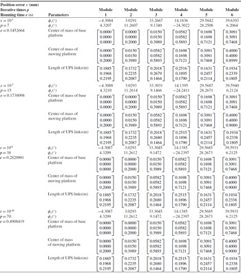
Inverse displacement solutions for different values of position error
 $\varepsilon$

(2) Angle of the universal joint of the central link
The rotation angle
 $\theta _{k}$
of the moving platform can be regarded as the angle between the central links of two adjacent parallel modules, as shown in Eq. (15):
 \begin{equation} \theta _{k}=\arcsin ({\boldsymbol{r}}_{k}\times {\boldsymbol{r}}_{k+1}) \end{equation}
where
 ${\boldsymbol{r}}_{k}$
and
 ${\boldsymbol{r}}_{k+1}$
denote the vector of the central link of the
 $k-\mathrm{th}$
parallel module and the
 $(k+1)-\mathrm{th}$
parallel module. Only when
 $\theta _{k}\leq \theta _{\max }$
, the result can be considered as meeting the constraints. Otherwise,
 $\theta _{k}$
should be updated using the following methods until Eq. (15) is satisfied:
a. In the forward iteration,
 ${\boldsymbol{c}}_{k}$
denotes a vector of the same length and opposite direction to
 ${\boldsymbol{r}}_{k+1}$
, as shown in Eq. (16), and
 ${\boldsymbol{h}}_{k}$
denotes the plane normal vector by the right-hand screw rule, according to vector
 ${\boldsymbol{r}}_{k+1}$
and vector
 ${\boldsymbol{r}}_{k}$
. When
 $\theta _{k}\leq \theta _{\max }$
is not satisfied, let
 ${\boldsymbol{h}}_{k}$
be the rotation axis and rotate the vector
 ${\boldsymbol{v}}_{k}$
by
 $\theta _{\max }$
according to the right-hand screw rule, to obtain the updated vector
 ${\boldsymbol{r}}_{k}$
:
 \begin{equation} {\boldsymbol{c}}_{k}=-{\boldsymbol{r}}_{k+1} \end{equation}
 \begin{equation} {\boldsymbol{h}}_{k}={\boldsymbol{r}}_{k+1}\times {\boldsymbol{r}}_{k} \end{equation}
b. In the backward iteration,
 ${\boldsymbol{c}}_{k}$
is a vector of the same length and direction as
 ${\boldsymbol{r}}_{k}$
, as shown in Eq. (18), and
 ${\boldsymbol{h}}_{k}$
is the plane normal vector by the right-hand screw rule according to vector
 ${\boldsymbol{r}}_{k}$
and vector
 ${\boldsymbol{r}}_{k+1}$
. When
 $\theta _{k}\leq \theta _{\max }$
is not satisfied, set
 $\theta _{k}=\theta _{\max }$
, let
 ${\boldsymbol{h}}_{k}$
be the rotation axis, and rotate the vector
 ${\boldsymbol{v}}_{k}$
by
 $\theta _{k}$
according to the right-hand screw rule. Calculate the updated vector
 ${\boldsymbol{r}}_{k+1}$
and ensure the angle constraint of the universal joint is met. Otherwise, let
 $\theta _{k}=\theta _{k}-\Delta \theta$
and recalculate
 ${\boldsymbol{v}}_{k}$
and
 ${\boldsymbol{m}}_{k}$
until the updated vector
 ${\boldsymbol{r}}_{k+1}$
meets the angle constraint of the universal joint:
 \begin{equation} {\boldsymbol{c}}_{k}={\boldsymbol{r}}_{k} \end{equation}
 \begin{equation} {\boldsymbol{h}}_{k}={\boldsymbol{r}}_{k}\times {\boldsymbol{r}}_{k+1} \end{equation}
Configuration of the HRETR’s central link without constraint conditions.

Configuration of the HRETR’s central link with constraint conditions.

HRETR configuration with constraint conditions.

(3) Angle of the universal joint of the UPS links
At the center of rotation of the universal joint of the
 $i-\mathrm{th}$
UPS link of the
 $k-\mathrm{th}$
parallel module, let the
 $z-\text{axis}$
point to the moving platform. The two vertical axes of the universal joint are the
 $x-\text{axis}$
and
 $y-\text{axis}$
, respectively, where the
 $x-\text{axis}$
points to the center of the base platform.
 $\;{_{}^{k-1}}{{\boldsymbol{w}}}{_{ki}^{}}$
is the vector expression of the i-th kinematics chain of the k-th parallel module in the k-th reference coordinate system and can be described by:
 \begin{equation} {_{}^{k-1}}{{\boldsymbol{w}}}{_{ki}^{}}={_{}^{k-1}}{{\boldsymbol{R}}}{_{ki}^{}}({_{}^{k-1}}{{\boldsymbol{r}}}{_{k}^{}}/d) \end{equation}
where
 ${_{}^{k-1}}{{\boldsymbol{R}}}{_{ki}^{}}$
donates the transformation relationship between the direction vector of the i-th UPS link of the k-th parallel module and the central link of the same parallel module and it can be described by:
 \begin{equation} {_{}^{k-1}}{{\boldsymbol{R}}}{_{ki}^{}}=\mathrm{Rot}(z,\pi /3)\mathrm{Rot}(y',\varphi _{kiy})\mathrm{Rot}(x'',\varphi _{kix}) \end{equation}
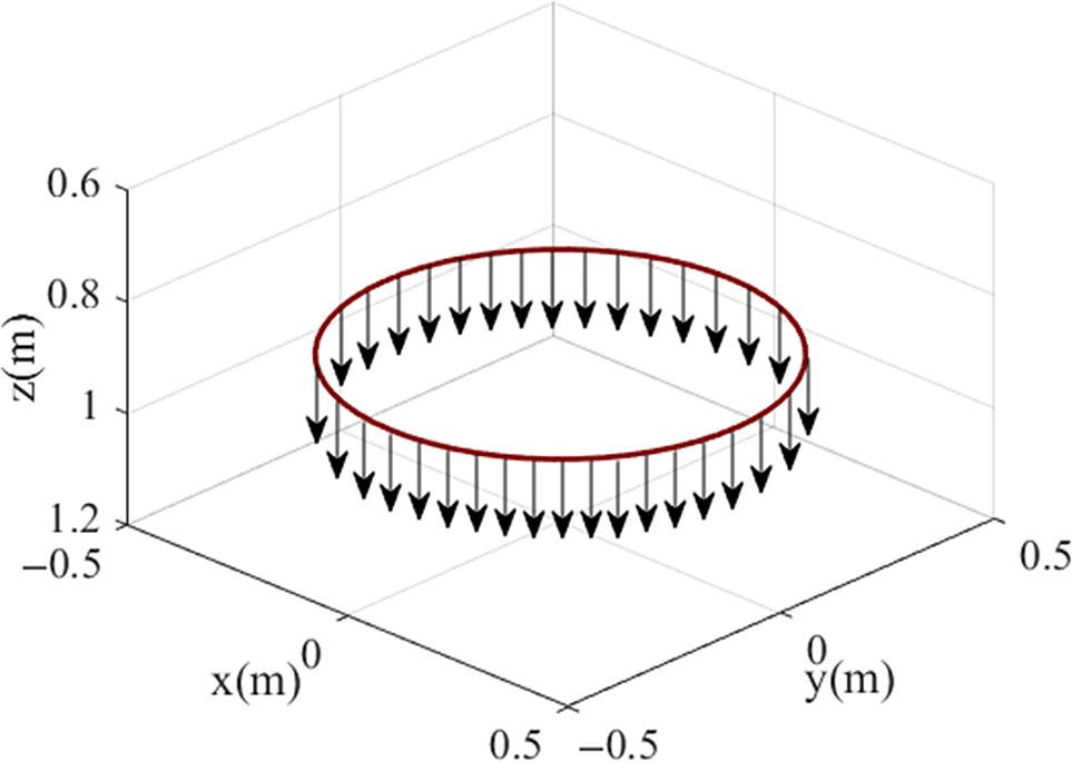
Trajectory 1: The normal vector at the end remains vertical and downward.

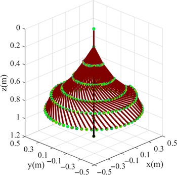
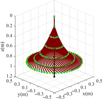
HRETR configuration along trajectory 1.

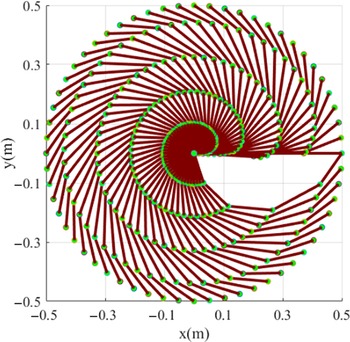
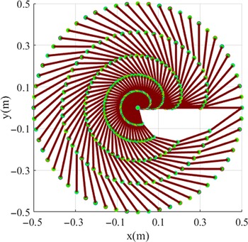
Top view of HRETR configurations along trajectory 1.

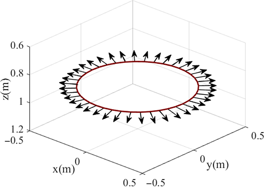
Trajectory 2: The normal vector at the end is divergent all around.

Due to the hyper-redundant mechanical structure, each two adjacent parallel modules are arranged at an interval of angle along the direction of the z-axis and the rotation angle with the z-axis is
 $\pi /3$
. Then the rotation angle of the universal joint of the
 $k-\mathrm{th}$
parallel module’s
 $i-\mathrm{th}$
UPS can be obtained by:
 \begin{align} \begin{cases} \varphi _{kix}=\arcsin \left(\dfrac{\sqrt{3}{_{}^{k-1}}{w}{_{kix}^{}}-{_{}^{k-1}}{w}{_{kiy}^{}}}{2}\right)\\[12pt] \varphi _{kiy}=\arctan \left(\dfrac{{_{}^{k-1}}{w}{_{kix}^{}}+\sqrt{3}{_{}^{k-1}}{w}{_{kiy}^{}}}{2{_{}^{i-1}}{w}{_{kiz}^{}}}\right) \end{cases} \end{align}
The rotation range of the universal joint of the
 $i-\mathrm{th}$
UPS link of the
 $k-\mathrm{th}$
parallel module should meet the following constraints:
 \begin{align} \begin{cases} \varphi _{kix}\leq \varphi _{kix\max }\\[5pt] \varphi _{kiy}\leq \varphi _{kiy\max } \end{cases} \end{align}
when the universal joint’s rotation angle does not satisfy the rotation range, let
 $\theta _{k}=\theta _{k}-\Delta \theta$
and recalculate
 $\varphi _{kix}$
and
 $\varphi _{kix}$
until the angle constraint is satisfied.
HRETR configuration along trajectory 2.

Top view of HRETR configurations along trajectory 2.

(4) Angle of the spherical joint of the UPS links
Assuming the initial installation angle of the spherical joint of the UPS links is
 $\gamma _{0}$
, the normal vector of the spherical joint installation plane can be obtained from the normal vector of the moving platform through the
 $y-x-y$
Euler angle rotation transformation which can be described by:
 \begin{equation} {\boldsymbol{R}}_{in}=\mathrm{Rot}\left(y,-\frac{\pi }{2}\right)\mathrm{Rot}\left(x',-\beta _{i}\right)\mathrm{Rot}\left(y'',\frac{\pi }{2}-\gamma _{0}\right) \end{equation}
where
 $\boldsymbol{\beta }=\left[\begin{array}{l@{\quad}l@{\quad}l} 0 & 2\pi /3 & 4\pi /3 \end{array}\right]$
denotes the angle between the two adjacent spherical joints on the moving platform. The rotation angle of the spherical joint of the
 $i-\mathrm{th}$
UPS link of the
 $k-\mathrm{th}$
parallel module is then given by:
 \begin{equation} \eta _{ki}=\arccos (({_{}^{Ok-_{1}}}{{\boldsymbol{R}}}{_{Ok}^{}}{\boldsymbol{R}}_{ki}{\boldsymbol{r}}_{k})^{T}{_{}^{k-1}}{{\boldsymbol{w}}}{_{ki}^{}}) \end{equation}
where
 ${_{}^{k-1}}{{\boldsymbol{w}}}{_{ki}^{}}$
is the direction vector of the central link vector of the
 $k-\mathrm{th}$
parallel module in its own base platform coordinate system. The angle constraint of the spherical joint should meet
 $\eta _{ki}\leq \eta _{ki,\max }$
. Otherwise, let
 $\theta _{k}=\theta _{k}-\Delta \theta$
and recalculate
 $\eta _{ki}$
until the angle constraint is satisfied.
The complete flow chart for the HRETR inverse displacement solution algorithm is shown in Fig. 8.
Position error, iteration times, and operating time with trajectory 1

4. Numerical example
The parameters of the HRETR’s mechanical structure are given in the following tables. Tables I and II present the radius of each platform of the HRETR and the lengths of the sleeves and push rods in each module’s UPS link, respectively. The target point’s position and orientation are given as
 $\left[\begin{array}{c@{\quad}c@{\quad}c@{\quad}c@{\quad}c} 0.4 & 0.4 & 0.9 & 0 & 0 \end{array}\right]^{T}$
, where the first three values describe the position of the target and the last two values denote its orientation. Inverse displacement solutions for different values of position error
 $\varepsilon$
(mm) are shown in Table III, where, p is the iterative times and e (s) is the running time.
 $\varphi$
x
and
 $\varphi$
y
denote the rotation angle of the moving platform concerning its own base platform. The numerical example was implemented using an Intel i7-7700 (3.6 GHz) processor, 8 GB RAM, and MATLAB® software.
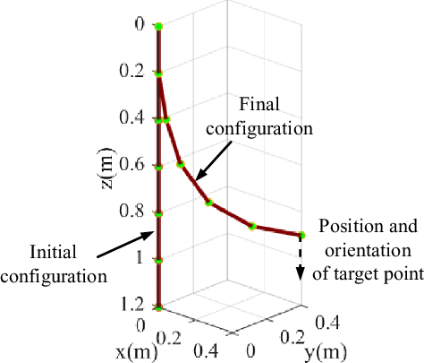
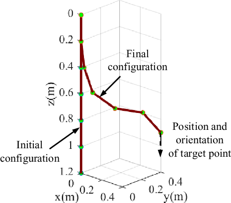
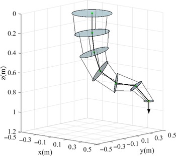
The HRETR’s central link configurations are shown without and with constraint conditions in Figs. 9 and 10, respectively. The solid red line denotes each module’s central link, and the green dot represents the each platform mass center. To verify the HRETR’s inverse displacement, its configuration was obtained based on the iterative algorithm and inverse displacement model proposed in this paper, as shown in Fig. 11. The simulation result obtained demonstrates the accuracy of the algorithm and model.
To verify the inverse displacement algorithm’s effectiveness, two trajectories with different constraint conditions were provided to simulate the moving configuration of an HRETR composed of six parallel modules in series. The HRETR’s configuration, when its end effector reached the given path points, was calculated and the result were analyzed.
The two circular trajectories are shown in Figs. 12 and 15, the radius was 0.5 m. Taking 60 path points on the two circular trajectories, respectively, the normal vector of the robot’s end point must be vertical and downward at each point in Fig. 12 and the normal vector is required to be divergent to all around in Fig. 15. The HRETR’s initial configuration is vertical and down before the simulation. Because of the difference in the position and orientation of the HRETR’s end effector in two circular trajectories and the joint constraint conditions are existed in this algorithm, the configurations of the HRETR are different. As shown in Figs. 13 and 16, the end of the HRETR initially reaches the first target point on the trajectory, and then the HRETR’s configuration at the remaining target points is solved by the iterative algorithm. Considering the end moving platform’s normal vector to be the virtual central link and calculating the angle between the two adjacent central links and the UPS link’s length continuously ensures the constraints are met. Due to the joint constraint conditions of the HRETR, six joints need to be verified if the joint constraint conditions are satisfied or not. If the angle between the two adjacent central links and the UPS link’s length satisfies the constraint conditions, the end effector of the HRETR will reach the next target point. If not, the joints need to adjust the pose and position to meet the constraint conditions. Until all the constraints conditions are met, the end effector of the HRETR will reach to the next target point. When the end of the HRETR returns to the first target point again, the simulation ends. Figs. 13, 14, 16 and 17 show the HRETR’s configuration change with and without constraints.
To illustrate the effectiveness of the algorithm, a numerical example was implemented on an Intel i7-7700 (3.6 GHz) processor with 8 GB RAM. The algorithm was run 100 times for the trajectory 1, as shown in Fig. 13 and calculated the average running time. The results are shown in Table IV.
5. Conclusions
This paper introduces an iterative algorithm for solving the inverse displacement of an HRETR. The HRETR which is composed of six parallel modules is presented in the paper. The work can be summarized as follows:
Each of the HRETR’s parallel modules is abstracted as a geometric line segment and point model, and then the inverse displacement of the HRETR composed of six parallel modules is implemented. The algorithm process can be divided into forward iteration and backward iteration according to the principle of forward approximation and inverse pose adjustment. The inverse displacement of the HRETR is obtained while considering physical joint constraints. The inverse displacement problem of the HRETR is considered to solve the transformation matrices of each parallel module firstly, and then the inverse displacement of the parallel module is obtained. In this way, the complex inverse displacement problem of the HRETR is transformed into the inverse displacement of the parallel module.
The algorithm considering the joints constraints was used to simulate the HRETR composed of six parallel modules in series. The simulation results demonstrate that motion and configuration of the HRETR are guaranteed to be smooth. The algorithm uses simple geometric elements instead of complex structure to describe the joint position relationships of the HRETR, which can be generalized for solving the inverse displacement of an HRETR.
Acknowledgments
The research is jointly supported by the National Natural Science Foundation of China (Grant No. 51375288), the Science and Technology Program of Guangdong Province (Grant No. 2020ST004), and the Special Project for Science and Technology Innovation Team of Foshan City (Grant No. 2018IT100052). The authors would also like to thank the anonymous reviewers for their very useful comments.
Author contributions
Feifei Yuan and Yongjie Zhao conceived and designed the study. Yongxing Zhang and Xingwei Zhang conducted data gathering. Xinjian Lu performed statistical analyses. Feifei Yuan and Yongjie Zhao wrote the article.
Competing interests declaration
No competing financial interests exist.