

1. Introduction
1.1 DNA damages
The DNA is attacked daily by ultraviolet (UV) radiation, chemical carcinogens, cellular metabolites as well as anti-cancer drugs such as cisplatin (Hoeijmakers, Reference Hoeijmakers2001) leading to more than 50 000 damages per cell per day (Rajski et al. Reference Rajski, Jackson and Barton2000). To preserve the integrity of the genetic information, all organisms are equipped with a number of DNA repair or tolerance mechanisms such as DNA recombination, base excision repair (BER), mismatch repair (MMR), nucleotide excision repair (NER) and translesion synthesis (TLS) that allow cells to cope with the different lesions (Friedberg, Reference Friedberg2005; Ohmori et al. Reference Ohmori, Friedberg, Fuchs, Goodman, Hanaoka, Hinkle, Kunkel, Lawrence, Livneh, Nohmi, Prakash, Prakash, Todo, Walker, Wang and Woodgate2001; Rupp & Howard-Flanders, Reference Rupp and Howard-Flanders1968). In this review, we will focus on eukaryotic NER and TLS.
1.2 NER and NER-related diseases
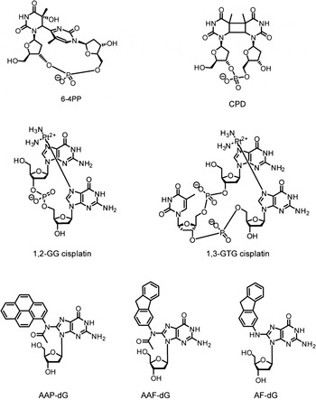
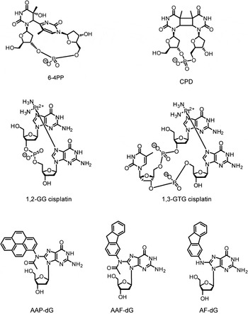
One of the most prominent processes among the DNA repair pathways is the NER. NER is a central pathway safeguarding the genome and cells against induced carcinogenesis, because of its capacity to eliminate a broad range of structurally very different DNA lesions (de Laat et al. Reference de Laat, Jaspers and Hoeijmakers1999; Geacintov et al. Reference Geacintov, Broyde, Buterin, Naegeli, Wu, Yan and Patel2002; Gillet & Scharer, Reference Gillet and Scharer2006; Gunz et al. Reference Gunz, Hess and Naegeli1996; Huang et al. Reference Huang, Hsu, Kazantsev and Sancar1994) including UV lesions such as cyclobutane–pyrimidine dimers (CPDs) and 6–4 pyrimidine–pyrimidone photoproducts (6-4PPs), numerous bulky chemical adducts, intrastrand crosslinks caused by chemotherapeutics such as cisplatin and oxidative damages (Fig. 1) (Brooks et al. Reference Brooks, Wise, Berry, Kosmoski, Smerdon, Somers, Mackie, Spoonde, Ackerman, Coleman, Tarone and Robbins2000; Demple & Harrison, Reference Demple and Harrison1994). All these lesions do not share the same chemical structures, but they are bulky and they thermodynamically destabilize the DNA helix, except for CPDs.
Examples of DNA adducts repaired by NER. AAF-dG: N-(2′-desoxyguanosin-8-yl)-2-acetylaminofluorene, AF-dG: N-(2′-desoxyguanosin-8-yl)-2-aminofluorene AAP-dG: N-(2′-desoxyguanosin-8-yl)-2-acetylaminopyrene 6–4PP: 6–4PP, CPD: cyclobutane–pyrimidine dimer, 1,2-GG and 1,3-GTG: major cisplatin-induced intrastrand crosslinks lesions.
In humans, mutations of NER components lead to three severe diseases: xeroderma pigmentosum (XP), Cockayne syndrome (CS) and trichothiodystrophy (TTD) (Cleaver, Reference Cleaver2000; Lehmann, Reference Lehmann2001). The NER pathway is divided in two subpathways: the global genome NER (GG-NER) and the transcription-coupled NER (TC-NER) (Gillet & Scharer, Reference Gillet and Scharer2006; Hanawalt & Spivak, Reference Hanawalt and Spivak2008) differing only in their damage recognition step. But NER in chromatin is a complex process and probably uses the proposed ‘access–repair–restore’ mechanism, which comprises many components (Scharer, Reference Scharer2013). A defect in TC-NER along with a mild transcription effect can cause CS and TTD (Cleaver et al. Reference Cleaver, Lam and Revet2009).
The CS is characterized by developmental impairment, premature aging and sunlight sensitivity. TTD leads to developmental impairment and mental retardation without showing skin cancer predisposition (Cleaver et al. Reference Cleaver, Lam and Revet2009; Lehmann, Reference Lehmann2003). Mutations inactivating the GG-NER cause the genetic disorder XP (Cleaver et al. Reference Cleaver, Lam and Revet2009). Persons affected by XP (‘children of the moon’) need to avoid exposure to sunlight, because they show a high predisposition to UV-induced skin cancer (Berneburg & Lehmann, Reference Berneburg and Lehmann2001; Hebra & Kaposi, Reference Hebra and Kaposi1874; Lehmann, Reference Lehmann2003). Seven complementation groups (XPA–XPG) associated with different NER gene defects were discovered by cell fusion techniques (De Weerd-Kastelein et al. Reference De Weerd-Kastelein, Keijzer and Bootsma1972). The discovery of NER and its association with genetic disorders together with the mechanism of action have already been reviewed (Friedberg, Reference Friedberg1995). Mutations associated with XP and posttranslational modifications of the XP proteins have also been recently reported (Feltes & Bonatto, Reference Feltes and Bonatto2015). The variant form of the human syndrome xeroderma pigmentosum (XPV) (Masutani et al. Reference Masutani, Kusumoto, Yamada, Dohmae, Yokoi, Yuasa, Araki, Iwai, Takio and Hanaoka1999b) is caused by a defect in DNA polymerase ɳ. In this paper, we review the eukaryotic structures of XP proteins (XPA–XPG), including the XP variant DNA polymerase ɳ (called XPV) in complex with damaged or undamaged DNA. This review will provide insights at the atomic level of how lesions in DNA are processed by these proteins.
1.3 NER mechanism
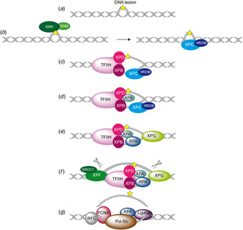
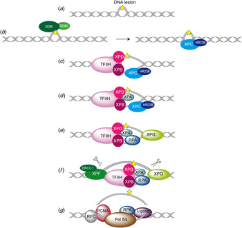
With the exception of chromatin, the NER mechanism is well understood in Escherichia coli as well as in eukaryotes (Naegeli & Sugasawa, Reference Naegeli and Sugasawa2011; Sancar & Tang, Reference Sancar and Tang1993; Scharer, Reference Scharer2013). While the repair process in eukaryotes is accomplished by up to 30 proteins, the precise role of each protein has not been fully elucidated so far. Despite this, a general core repair mechanism has emerged (Fig. 2). In eukaryotes, the NER is divided in two distinct subpathways differing only in their damage recognition step (de Laat et al. Reference de Laat, Jaspers and Hoeijmakers1999; Hanawalt & Spivak, Reference Hanawalt and Spivak2008; Mellon et al. Reference Mellon, Spivak and Hanawalt1987). TC-NER ensures the repair of lesions which are located on the transcribed strand of active genes (Hanawalt & Spivak, Reference Hanawalt and Spivak2008; Hoeijmakers, Reference Hoeijmakers2001; Mellon et al. Reference Mellon, Spivak and Hanawalt1987; Sweder & Hanawalt, Reference Sweder and Hanawalt1992). Here the RNA-polymerase II seems to act as the initial damage sensor. During transcription the polymerase gets stalled at the lesion site (Donahue et al. Reference Donahue, Yin, Taylor, Reines and Hanawalt1994; Tornaletti & Hanawalt, Reference Tornaletti and Hanawalt1999) and by addition of the protein Cockayne syndrome group B (CSB) a stable CSB–RNAP–DNA complex can from by ATP-hydrolysis (Citterio et al. Reference Citterio, Van Den Boom, Schnitzler, Kanaar, Bonte, Kingston, Hoeijmakers and Vermeulen2000; Tantin et al. Reference Tantin, Kansal and Carey1997). In case the lesion blocks any read through, downstream factors such as Cockayne syndrome group A protein (CSA) (Kamiuchi et al. Reference Kamiuchi, Saijo, Citterio, de Jager, Hoeijmakers and Tanaka2002), TFIIH (Tantin, Reference Tantin1998) and XPG (Iyer et al. Reference Iyer, Reagan, Wu, Canagarajah and Friedberg1996) are recruited to the damage site and repair is initiated (Hanawalt & Spivak, Reference Hanawalt and Spivak2008). The GG-NER in contrast detects and removes helix distorting lesions throughout the whole genome. The exact mechanism of the damage recognition steps is still under debate. Aboussekhra et al. and Mu et al. were able to reconstitute the repair mechanism in vitro allowing deciphering the core excision reaction of NER (Aboussekhra et al. Reference Aboussekhra, Biggerstaff, Shivji, Vilpo, Moncollin, Podust, Protic, Hubscher, Egly and Wood1995; Mu et al. Reference Mu, Park, Matsunaga, Hsu, Reardon and Sancar1995). The NER assembly seems to be a sequential and coordinated process in which damage excision and repair is mostly error-free. This repair process is characterized by five main steps (steps I–V): after damage recognition (I) a multi-protein complex (‘preincision complex’ (PIC)) binds to the damage site (II) leading to a double asymmetric cut of the damage-containing oligonucleotide strand. The damage-containing single-stranded DNA (ssDNA) fragment is eliminated (III). Afterwards the double strand is reconstituted by filling the gap with the DNA polymerase (IV) and ligation of the new synthesized strand takes place (V) (Shivji et al. Reference Shivji, Podust, Hubscher and Wood1995). In this work, we will only consider the GG-NER pathway.
Overview of the global genome-NER mechanism (Friedberg, Reference Friedberg2001; Li et al. Reference Li, Golebiowski, Onishi, Samara, Sugasawa and Yang2015).
1.4 DNA-structure/repair relationships
Because of its broad substrate specificity, it was speculated early on that the NER system does not recognize the lesion itself but the distortion of the DNA structure. In 1997 Naegeli and co-workers discovered that for damage recognition a chemical modification of the nucleotide in addition to distortion in the DNA helix had to be present (Hess et al. Reference Hess, Schwitter, Petretta, Giese and Naegeli1996b). They could show that neither a modified ribose moiety with intact Watson–Crick base pairing nor a DNA bubble of three base-pairs was recognized and repaired by the NER system. However, placing the modified ribose moiety into a DNA bubble, created a well-recognized NER substrate. These observations helped to formulate the ‘bipartite substrate discrimination’-model (Hess et al. Reference Hess, Gunz and Naegeli1996a, Reference Hess, Gunz, Luneva, Geacintov and Naegeli1997a). This model shows that only DNA damages that cause disrupted base pairing can be recognized as NER substrates. Furthermore, a DNA helix distortion might be additionally needed for the correct recruitment of the NER machinery (Hess et al. Reference Hess, Schwitter, Petretta, Giese and Naegeli1996b). This hypothesis explains why helix-distorting damages are more efficiently processed by NER (Gunz et al. Reference Gunz, Hess and Naegeli1996; Sugasawa et al. Reference Sugasawa, Okamoto, Shimizu, Masutani, Iwai and Hanaoka2001). These ideas can also explain why 6–4PPs are better substrates than CPD lesions. Not all adducts, induced by polyaromatic hydrocarbons or aromatic amines, are good substrates for NER, because some adducts do not change the duplex structure, e.g. N-(deoxyguanosin-8-yl)-2-aminofluorene. The aromatic ring of the lesion is easily accommodated in the minor or major grooves of the DNA duplex. Lesions causing helix disruption upon intercalation of their aromatic ring inside the DNA helix are typically good substrates for NER, e.g. N-(deoxyguanosin-8-yl)-2-acetylaminofluorene (dG-AAF), (Gillet et al. Reference Gillet, Alzeer and Scharer2005; Mu et al. Reference Mu, Bertrand-Burggraf, Huang, Fuchs, Sancar and Fuchs1994) or benzo[a]pyrene (Buterin et al. Reference Buterin, Hess, Luneva, Geacintov, Amin, Kroth, Seidel and Naegeli2000; Geacintov et al. Reference Geacintov, Broyde, Buterin, Naegeli, Wu, Yan and Patel2002; Hess et al. Reference Hess, Gunz, Luneva, Geacintov and Naegeli1997a; Yan et al. Reference Yan, Wu, Buterin, Naegeli, Geacintov and Broyde2003). Nowadays, it is assumed that all parameters able to reduce the thermodynamic stability of the DNA play a role for the NER damage recognition step. The repair rate is apparently proportional to the decrease of thermodynamic stability of the duplex induced by the discrete DNA lesions (Aboussekhra et al. Reference Aboussekhra, Biggerstaff, Shivji, Vilpo, Moncollin, Podust, Protic, Hubscher, Egly and Wood1995; Geacintov et al. Reference Geacintov, Broyde, Buterin, Naegeli, Wu, Yan and Patel2002; Gillet & Scharer, Reference Gillet and Scharer2006; Gunz et al. Reference Gunz, Hess and Naegeli1996).
1.5 Damage recognition in NER
How does discrimination between undamaged and damaged DNA take place in the context of dominating undamaged DNA present in the nucleus? The exact damage recognition process in NER is still unclear and as such it is the most challenging current question associated with the NER process.
Several experiments with fluorescein-labeled proteins, such as ERCC1 (Houtsmuller et al. Reference Houtsmuller, Rademakers, Nigg, Hoogstraten, Hoeijmakers and Vermeulen1999), XPB (Hoogstraten et al. Reference Hoogstraten, Nigg, Heath, Mullenders, van Driel, Hoeijmakers, Vermeulen and Houtsmuller2002) and XPA (Rademakers et al. Reference Rademakers, Volker, Hoogstraten, Nigg, Mone, Van Zeeland, Hoeijmakers, Houtsmuller and Vermeulen2003), in combination with photobleaching techniques showed that the repair proteins move freely in the nucleus and accumulate successively at the damaged site. These observations argue that recognition factors must initially bind to the damage site and subsequently recruit downstream factors. At the beginning of NER research XPA was thought to be the initial damage recognizer in NER (Asahina et al. Reference Asahina, Kuraoka, Shirakawa, Morita, Miura, Miyamoto, Ohtsuka, Okada and Tanaka1994; Jones & Wood, Reference Jones and Wood1993). However, in 1998 Sugasawa et al. (Sugasawa et al. Reference Sugasawa, Ng, Masutani, Iwai, van der Spek, Eker, Hanaoka, Bootsma and Hoeijmakers1998) demonstrated in an in vitro experiment, that the complex XPC–RAD23B was the first damage binder followed by participation of XPA. While for XPC–RAD23B the involvement in the GG-NER pathway has been clearly shown, the complex is not necessary for TC-NER. XPA in contrast, is indispensable for both GG-NER and TC-NER, which perhaps supports its central function in a later step of NER (Kobayashi et al. Reference Kobayashi, Takeuchi, Saijo, Nakatsu, Morioka, Otsuka, Wakasugi, Nikaido and Tanaka1998; Sugasawa et al. Reference Sugasawa, Ng, Masutani, Iwai, van der Spek, Eker, Hanaoka, Bootsma and Hoeijmakers1998). The role of XPA requires further investigations.
Biochemical experiments demonstrated that the UV-damaged DNA-binding protein (UV-DDB) (Fujiwara et al. Reference Fujiwara, Masutani, Mizukoshi, Kondo, Hanaoka and Iwai1999; Keeney et al. Reference Keeney, Chang and Linn1993; Reardon et al. Reference Reardon, Nichols, Keeney, Smith, Taylor, Linn and Sancar1993), XPC–RAD23B (Batty et al. Reference Batty, Rapic’-Otrin, Levine and Wood2000a; Raoul et al. Reference Raoul, Bardet and Cadet1995; Sugasawa et al. Reference Sugasawa, Ng, Masutani, Iwai, van der Spek, Eker, Hanaoka, Bootsma and Hoeijmakers1998, Reference Sugasawa, Okamoto, Shimizu, Masutani, Iwai and Hanaoka2001), XPA (Buschta-Hedayat et al. Reference Buschta-Hedayat, Buterin, Hess, Missura and Naegeli1999; Jones & Wood, Reference Jones and Wood1993; Li et al. Reference Li, Lu, Peterson and Legerski1995a) and replication protein A (RPA) (Burns et al. Reference Burns, Guzder, Sung, Prakash and Prakash1996; Mellon et al. Reference Mellon, Spivak and Hanawalt1987; Reardon & Sancar, Reference Reardon and Sancar2002; Schweizer et al. Reference Schweizer, Hey, Lipps and Krauss1999) show all affinity to damage-containing DNA. XPC–RAD23B binds specifically to DNA lesions such as 6–4PP (Batty et al. Reference Batty, Rapic’-Otrin, Levine and Wood2000a; Kusumoto et al. Reference Kusumoto, Masutani, Sugasawa, Iwai, Araki, Uchida, Mizukoshi and Hanaoka2001; Raoul et al. Reference Raoul, Bardet and Cadet1995), cisplatin (Evans et al. Reference Evans, Moggs, Hwang, Egly and Wood1997b; Hey et al. Reference Hey, Lipps, Sugasawa, Iwai, Hanaoka and Krauss2002; Moggs et al. Reference Moggs, Yarema, Essigmann and Wood1996, Reference Moggs, Szymkowski, Yamada, Karran and Wood1997; Sugasawa et al. Reference Sugasawa, Ng, Masutani, Iwai, van der Spek, Eker, Hanaoka, Bootsma and Hoeijmakers1998), dG-AAF (Sugasawa et al. Reference Sugasawa, Ng, Masutani, Iwai, van der Spek, Eker, Hanaoka, Bootsma and Hoeijmakers1998) and cholesterol adducts (Kusumoto et al. Reference Kusumoto, Masutani, Sugasawa, Iwai, Araki, Uchida, Mizukoshi and Hanaoka2001; Sugasawa et al. Reference Sugasawa, Okamoto, Shimizu, Masutani, Iwai and Hanaoka2001). It recognizes CPD damages (Kusumoto et al. Reference Kusumoto, Masutani, Sugasawa, Iwai, Araki, Uchida, Mizukoshi and Hanaoka2001) poorly although their repair is strongly dependent on the presence of XPC (Venema et al. Reference Venema, van Hoffen, Karcagi, Natarajan, van Zeeland and Mullenders1991). The affinity of XPC–RAD23B to CPDs can be enhanced by mismatches surrounding the lesion (Sugasawa et al. Reference Sugasawa, Okamoto, Shimizu, Masutani, Iwai and Hanaoka2001). XPA alone or in combination with RPA binds to DNA containing bulky adducts such as dG-AAF (Liu et al. Reference Liu, Yang, Utzat, Wang, Basu and Zou2005; Yang et al. Reference Yang, Liu, Mao, Zhang and Zou2002). By far the strongest DNA binding for XPA are DNA junctions which suggest that XPA interacts with an intermediate structure rather than directly with a lesion (Missura et al. Reference Missura, Buterin, Hindges, Hubscher, Kasparkova, Brabec and Naegeli2001). Photoaffinity-crosslinking experiments demonstrate that XPC–RAD23B (Maltseva et al. Reference Maltseva, Rechkunova, Gillet, Petruseva, Scharer and Lavrik2007), as well as XPA (Wakasugi & Sancar, Reference Wakasugi and Sancar1999) show a high affinity to damaged DNA without binding directly to the lesion (Reardon & Sancar, Reference Reardon and Sancar2002). Reconstitution experiments with NER-deficient cells with all the different NER proteins in different order delivered contradictory results. Sugasawa et al. showed a fast repair rate when the cells where preincubated with XPC–RAD23B (Sugasawa et al. Reference Sugasawa, Ng, Masutani, Iwai, van der Spek, Eker, Hanaoka, Bootsma and Hoeijmakers1998). Preincubation of the damaged plasmids with XPA–RPA slowed down the repair velocity. Experiments from Wakasugi et al. however showed a more effective repair when damaged DNA was preincubated with XPA/RPA (Wakasugi & Sancar, Reference Wakasugi and Sancar1999).
1.6 Overview of each XP protein and its role in GG-NER
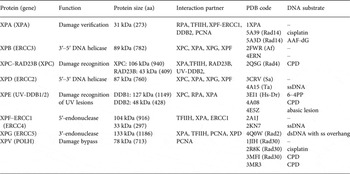
In Fig. 2, the different steps of the GG-NER mechanism are depicted. It is believed that XPC–RAD23B initiates the GR-NER by recognition of the damage (Fig. 2a, b ) (Reardon & Sancar, Reference Reardon and Sancar2003; Sugasawa et al. Reference Sugasawa, Ng, Masutani, Iwai, van der Spek, Eker, Hanaoka, Bootsma and Hoeijmakers1998; Wakasugi & Sancar, Reference Wakasugi and Sancar1998). XPC ignores the lesion but binds to the ssDNA opposite to the lesion (Min & Pavletich, Reference Min and Pavletich2007). In the case of UV lesions, the recognition process by XPC–RAD23B is sustained by the UV-DNA damage-binding protein 2 (UV-DDB2) (Luijsterburg et al. Reference Luijsterburg, von Bornstaedt, Gourdin, Politi, Mone, Warmerdam, Goedhart, Vermeulen, van Driel and Hofer2010; Min & Pavletich, Reference Min and Pavletich2007; Riedl et al. Reference Riedl, Hanaoka and Egly2003; Volker et al. Reference Volker, Mone, Karmakar, van Hoffen, Schul, Vermeulen, Hoeijmakers, van Driel, van Zeeland and Mullenders2001). After this step, the general transcription factor TFIIH is recruited to the lesion site using the energy provided by the ATPase activity of XPB (Fig. 2c ). Normally, TFIIH is involved in transcription by RNA polymerases I and II, but in the presence of DNA damage it is clearly recruited 5′ to the damage site (Hoogstraten et al. Reference Hoogstraten, Nigg, Heath, Mullenders, van Driel, Hoeijmakers, Vermeulen and Houtsmuller2002). Two subunits of TFIIH, the ATP-dependent DNA helicases XPB and XPD, are needed for ‘hooking up’ TFIIH at the lesion site performing further unwinding and damage verification. It is believed that XPB opens the DNA and facilitates the binding of XPD to the DNA which verifies the chemical modification of the lesion (Scharer, Reference Scharer2013). In addition, XPD scans the strand with the lesion and both helicases are stalled when XPD encounters a bulky lesion (Li et al. Reference Li, Golebiowski, Onishi, Samara, Sugasawa and Yang2015; Mathieu et al. Reference Mathieu, Kaczmarek, Ruthemann, Luch and Naegeli2013). In the next step, XPA and RPA (Fig. 2d, e ) are thought to be recruited to the damaged site to form the PIC which is stabilized by the structure specific endonucleases XPG (Fig. 2e ). Upon arrival of XPG to the PIC, XPC–RAD23B leaves the complex (Riedl et al. Reference Riedl, Hanaoka and Egly2003; Wakasugi & Sancar, Reference Wakasugi and Sancar1998). Besides XPD, XPA might be involved in damage verification, however, the details of this event remain elusive (Naegeli & Sugasawa, Reference Naegeli and Sugasawa2011; Tapias et al. Reference Tapias, Auriol, Forget, Enzlin, Scharer, Coin, Coulombe and Egly2004). The ssDNA-binding protein RPA now binds the undamaged strand, while TFIIH opens the duplex. XPA is then thought to recruit the structure specific endonuclease XPF–ERCC1 heterodimer (Li et al. Reference Li, Lu, Peterson and Legerski1995a; Tsodikov et al. Reference Tsodikov, Ivanov, Orelli, Staresincic, Shoshani, Oberman, Scharer, Wagner and Ellenberger2007) and incision on both sites of the lesion takes place. The first incision 5′ of the lesion is made by XPF–ERCC1 (Staresincic et al. Reference Staresincic, Fagbemi, Enzlin, Gourdin, Wijgers, Dunand-Sauthier, Giglia-Mari, Clarkson, Vermeulen and Scharer2009). Then, XPG cuts 3′ to the lesion (Fagbemi et al. Reference Fagbemi, Orelli and Scharer2011) triggering the elimination of a 24–32 oligonucleotide containing the lesion (Fig. 2f ) (Edenberg & Hanawalt, Reference Edenberg and Hanawalt1972; Evans et al. Reference Evans, Moggs, Hwang, Egly and Wood1997b; Ikegami et al. Reference Ikegami, Kuraoka, Saijo, Kodo, Kyogoku, Morikawa, Tanaka and Shirakawa1998). After that, DNA replication by the polymerases κ/δ/ε takes place sustained by other factors (PCNA, RFC and RPA) (Ogi et al. Reference Ogi, Limsirichaikul, Overmeer, Volker, Takenaka, Cloney, Nakazawa, Niimi, Miki, Jaspers, Mullenders, Yamashita, Fousteri and Lehmann2010). Finally, the new synthesized DNA strand is mostly sealed by DNA ligase III/XRCC1. DNA ligase I is only recruited to sites of UV damage in proliferating cells (Fig. 2g ) (Moser et al. Reference Moser, Kool, Giakzidis, Caldecott, Mullenders and Fousteri2001, Reference Moser, Kool, Giakzidis, Caldecott, Mullenders and Fousteri2007; Reardon & Sancar, Reference Reardon and Sancar2005; Wood, Reference Wood1997). Table 1 gives an overview of the XP proteins, their function and size, their interaction partners as well as the PDB codes of solved structures associated to the DNA substrates.
Overview of the XP proteins involved in NER and TLS. ERCCX: Excision repair cross-complementing rodent repair deficiency complementation group X. Af: Archaeoglobus fulgidus, Dr: Danio rerio, Sa: Sulfolobus acidocaldarius, Ape: Aeropyrum pernix, Ta: Thermoplasma acidophilum, AAF-dG: N-(2′-desoxyguanosin-8-yl)-2-acetylaminofluorene, 6–4PP: 6–4PP, CPD: cyclobutane–pyrimidine dimer. PDB codes depicted in bold refer to NMR structures.

2. XPE (UV-DDB2)
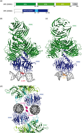
For the recognition of UV lesions such as 6–4PPs and CPD, the UV-DDB protein seems to promote binding of XPC–RAD23B to the damaged site (Scrima et al. Reference Scrima, Konickova, Czyzewski, Kawasaki, Jeffrey, Groisman, Nakatani, Iwai, Pavletich and Thoma2008). The UV-DDB protein, consists of the two subunits DDB1 (also called p127 with 127 kDa, 1149 amino acids) and DDB2 (called p48 with 48 kDa, 428 amino acids) (Fig. 3a ). It shows a 100- to 1000-fold higher affinity to photolesions than XPC–RAD23B (Keeney et al. Reference Keeney, Chang and Linn1993; Takao et al. Reference Takao, Abramic, Moos, Otrin, Wootton, McLenigan, Levine and Protic1993). Both subunits are required for the activity of the complex (Hwang et al. Reference Hwang, Toering, Francke and Chu1998a; Keeney et al. Reference Keeney, Chang and Linn1993; Nichols et al. Reference Nichols, Ong and Linn1996). UV-DDB is known to be involved in the DNA damage recognition process of GG-NER (Wakasugi et al. Reference Wakasugi, Kawashima, Morioka, Linn, Sancar, Mori, Nikaido and Matsunaga2002). The DDB2 subunit binds with preference to 6–4PPs but it also recognizes CPD lesions and it also binds abasic sites as well as DNA bubbles (Fujiwara et al. Reference Fujiwara, Masutani, Mizukoshi, Kondo, Hanaoka and Iwai1999). DDB1 is not involved in DNA binding. Mutation of the DDB2 subunit leads to a loss of function of the UV-DDB protein found in XP complementation group E (XPE) in patients (Chu & Chang, Reference Chu and Chang1988). XPE-deficient cells are shown to be defective in GG-NER (Hwang et al. Reference Hwang, Ford, Hanawalt and Chu1999). Wakasugi et al. showed that UV-DDB rapidly accumulates in vivo independently of XPA and XPC at DNA damage sites after UV-irradiation (Wakasugi et al. Reference Wakasugi, Kawashima, Morioka, Linn, Sancar, Mori, Nikaido and Matsunaga2002). Furthermore, they showed that UV lesions are mostly recognized by UV-DDB which then recruits XPA and XPC.
2.1 Crystal structure of human XPE with 6–4PP damaged dsDNA
Scrima et al. (Reference Scrima, Konickova, Czyzewski, Kawasaki, Jeffrey, Groisman, Nakatani, Iwai, Pavletich and Thoma2008) solved the crystal structure of the UV-DDB (human DDB1, HsDDB1 and the zebrafish DDB2 ortholog, DrDDB2) protein in complex with double-stranded DNA (dsDNA) containing the 6–4PP photolesion (Fig. 3b ). In order to achieve damage recognition the UV-DDB2 protein inserts a β-hairpin into the minor groove of the DNA. In addition, the damaged dinucleotide is flipped out of the double helix and inserted into a binding pocket of the protein leading to a DNA kink of about 40° at the lesion site. This destabilized conformation of the DNA might trigger the subsequent recruitment of XPC–RAD23B and further downstream factors. Due to the importance of DDB2, defective cells show a remarkable reduced CPD repair activity that gives rise to the XP-E phenotype (Hwang et al. Reference Hwang, Toering, Francke and Chu1998a; Tang et al. Reference Tang, Hwang, Ford, Hanawalt and Chu2000).
Crystal structures of the human XPE protein (UV-DDB). (a) Schematic representation of the human UV-DDB protein (DDB1 and DDB2) with the different domains. (b) Crystal structure of the XPE protein in complex with 6–4PP damaged DNA (PDB code: 3EI1) (Scrima et al. Reference Scrima, Konickova, Czyzewski, Kawasaki, Jeffrey, Groisman, Nakatani, Iwai, Pavletich and Thoma2008). DDB1 is depicted in green, DDB2 in blue, DNA in gray and the 6–4PP dinucleotide in red. (c) Crystal structure of XPE in complex with the CPD lesion (PDB code: 4A08) (Fischer et al. Reference Fischer, Scrima, Bohm, Matsumoto, Lingaraju, Faty, Yasuda, Cavadini, Wakasugi, Hanaoka, Iwai, Gut, Sugasawa and Thoma2011). DDB1 is depicted in green, DDB2 in blue, DNA in gray and the CPD lesion in orange. (d) Crystal structure of the dimeric human UV-DDB in a complex with an abasic lesion (PDB code: 4e5z) (Yeh et al. Reference Yeh, Levine, Du, Chinte, Ghodke, Wang, Shi, Hsieh, Conway, Van Houten and Rapić-Otrin2012). DDB1 is depicted in green, DDB2 in blue, DNA in dark gray, DDB2 α-paddle in cyan and the amino acid Asn360 in pink.

2.2 Crystal structure of human XPE with CPD damaged dsDNA
Fischer et al. (Reference Fischer, Scrima, Bohm, Matsumoto, Lingaraju, Faty, Yasuda, Cavadini, Wakasugi, Hanaoka, Iwai, Gut, Sugasawa and Thoma2011) obtained insight into the molecular basis of CPD lesion recognition by solving the crystal structure of the UV-DDB protein in complex with CPD containing DNA. For obtaining the structure, residues creating crystal contacts in the apo-protein that prevented protein crystallization were mutated. Consistent with the structure of Scrima et al. (Reference Scrima, Konickova, Czyzewski, Kawasaki, Jeffrey, Groisman, Nakatani, Iwai, Pavletich and Thoma2008) the CPD lesion is held by the DDB2 WD40 propeller. The crystal structure shows that the lesion recognition takes place with the help of a β-hairpin (‘finger’) consisting of the residues Phe371, Gln372 and His373 (Fig. 3c ). This β-hairpin inserts into the minor groove of the DNA duplex at the damage site and unwinds the duplex by 12.6°. Consequently the CPD lesion is extruded into an extrahelical, flipped-out state. Finally, the DNA shows also a kink angle of about 45° at the cis–syn CPD lesion site.
The UV-DDB protein is part of an ubiquitin ligase complex. The displacement of COP9 signalosome (CSN) from this complex by DDB2 substrate binding leads to ubiquitination of XPC and DDB2 (Groisman et al. Reference Groisman, Polanowska, Kuraoka, Sawada, Saijo, Drapkin, Kisselev, Tanaka and Nakatani2003; Luijsterburg et al. Reference Luijsterburg, Goedhart, Moser, Kool, Geverts, Houtsmuller, Mullenders, Vermeulen and Van Driel2007). This is thought to mediate the handover to XPC by stabilizing it, resulting in an increase of its affinity for damaged DNA, while the affinity of DDB2 to DNA containing a lesion is reduced (El-Mahdy et al. Reference El-Mahdy, Zhu, Wang, Wani, Praetorius-Ibba and Wani2006; Sugasawa et al. Reference Sugasawa, Okuda, Saijo, Nishi, Matsuda, Chu, Mori, Iwai, Tanaka, Tanaka and Hanaoka2005). Histones surrounding the lesion are ubiquitinated as well, which is suggested to slacken the nucleosome structure to promote recruitment of NER repair enzymes to the damage (Wang et al. Reference Wang, Zhai, Xu, Joo, Jackson, Erdjument-Bromage, Tempst, Xiong and Zhang2006).
2.3 Crystal structure of human XPE with an abasic lesion site in dsDNA
Yeh et al. (Reference Yeh, Levine, Du, Chinte, Ghodke, Wang, Shi, Hsieh, Conway, Van Houten and Rapić-Otrin2012) solved a dimeric crystal structure of UV-DDB (human DDB1 and DDB2) protein in complex dsDNA containing an abasic site (THF) (Fig. 3d ). Each DDB2 subunit is bound to one double-stranded oligonucleotide. The DDB2 residues Asn360/Asn360 are located between the two DNA strands spanning two antiparallel β-strands (β-wing) and giving rise to a 2-fold symmetry axis of the dimer. The crystal structure shows that the residues on the leading β-strand and loop form contacts with the undamaged DNA strand and the residues on the loop and the retreating β-strand form contacts with the neighboring undamaged DNA strand. These contacts are supported by additional interactions of the N-terminal-helical domain of DDB2 (α-paddle) with the neighboring DNA-strand which lead to dimerization, explaining the high affinity to damaged DNA.
3. XPC
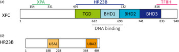
The human XPC protein is a polypeptide of 940 amino acids with a size of 106 kDa, forming a stable complex with the RAD23B protein (43 kDa, 409 amino acids). It is currently believed that XPC–RAD23B is responsible for the initial damage recognition with the exception of CPD lesions, where DDB2 is the first binding factor (Hey et al. Reference Hey, Lipps, Sugasawa, Iwai, Hanaoka and Krauss2002; Sugasawa et al. Reference Sugasawa, Okamoto, Shimizu, Masutani, Iwai and Hanaoka2001). The complex is known to interact with several other proteins, e.g. XPA and TFIIH (Fig. 4a, b ) (Araujo et al. Reference Araujo, Nigg and Wood2001; Bernardes de Jesus et al. Reference Bernardes de Jesus, Bjoras, Coin and Egly2008; Cleaver et al. Reference Cleaver, Lam and Revet2009). After binding, the protein recruits further downstream factors to the damaged site (Sugasawa et al. Reference Sugasawa, Ng, Masutani, Iwai, van der Spek, Eker, Hanaoka, Bootsma and Hoeijmakers1998). Biochemical assays show that the XPC–RAD23B complex binds with high affinity to different DNA lesions, e.g. 6–4PP and AAF-adducts (Batty & Wood, Reference Batty and Wood2000b; Sugasawa et al. Reference Sugasawa, Shimizu, Iwai and Hanaoka2002). The breakthrough came in 2001 when the Mullenders group was able to show that XPC might be the initial damage recognizer also for UV lesions. In the experiment, nuclei of living cells were irradiated with UV light at defined positions through a porous polycarbonate filter (Katsumi et al. Reference Katsumi, Kobayashi, Imoto, Nakagawa, Yamashina, Muramatsu, Shirai, Miyagawa, Sugiura, Hanaoka, Matsunaga, Nikaido and Mori2001; Mone et al. Reference Mone, Volker, Nikaido, Mullenders, van Zeeland, Verschure, Manders and van Driel2001; Volker et al. Reference Volker, Mone, Karmakar, van Hoffen, Schul, Vermeulen, Hoeijmakers, van Driel, van Zeeland and Mullenders2001). The generated UV lesions could be detected by antibodies specific against CPDs and 6–4PPs. To identify which NER factors were recruited to these sites they were also visualized with an appropriate antibody. This experiment revealed that XPC colocalized with UV lesion sites in XPA-deficient cells, while XPA was not recruited in XPC-deficient cells (Volker et al. Reference Volker, Mone, Karmakar, van Hoffen, Schul, Vermeulen, Hoeijmakers, van Driel, van Zeeland and Mullenders2001). Thus, it was concluded that XPA needs the presence of XPC to be recruited to the damaged site and that XPC is the first factor being recruited to the damaged site. Further investigations pointed out that XPC is also required to unwind the DNA at the damaged site in order to recruit NER downstream factors (Katsumi et al. Reference Katsumi, Kobayashi, Imoto, Nakagawa, Yamashina, Muramatsu, Shirai, Miyagawa, Sugiura, Hanaoka, Matsunaga, Nikaido and Mori2001; Mone et al. Reference Mone, Volker, Nikaido, Mullenders, van Zeeland, Verschure, Manders and van Driel2001). It has to be addressed that these experiments refer to the recognition of UV lesions. The general lesion recognition strategy adopted by XPC was established by a variety of experiments with different DNA lesions (Tapias et al. Reference Tapias, Auriol, Forget, Enzlin, Scharer, Coin, Coulombe and Egly2004). The helicase activity of XPD is not required for transcription but is indispensable for the NER process. The combined data show that XPC might be more structure specific than lesion specific. The XPC–RAD23B complex is able to recognize ssDNA (Maillard et al. Reference Maillard, Solyom and Naegeli2007) and DNA containing destabilizing lesions. Additionally it was shown, that the complex binds the DNA lesion in an asymmetric fashion (Sugasawa et al. Reference Sugasawa, Shimizu, Iwai and Hanaoka2002; Wakasugi & Sancar, Reference Wakasugi and Sancar1999). Interestingly, the complex also binds to 3−5 unpaired bases independently of the presence of damage. However, repair takes place only in the presence of DNA damage (Hess et al. Reference Hess, Schwitter, Petretta, Giese and Naegeli1997b; Sugasawa et al. Reference Sugasawa, Okamoto, Shimizu, Masutani, Iwai and Hanaoka2001).
Schematic representation of human XPC and RAD23B. (a) The TGD domain of XPC is depicted in green, the BHD1 domain in light blue, the BHD2 domain in blue and the BHD3 domain in dark blue. (b) The UBA1 and UBA2 domains of RAD23B are depicted in light orange and orange, respectively.

Hence, XPC might be a sensor for unpaired base pairs that occur in bubbles and loops and binds those in complex with RAD23B (Araki et al. Reference Araki, Masutani, Takemura, Uchida, Sugasawa, Kondoh, Ohkuma and Hanaoka2001; Van der Spek et al. Reference Van der Spek, Eker, Rademakers, Visser, Sugasawa, Masutani, Hanaoka, Bootsma and Hoeijmakers1996) and Centrin2 (Araki et al. Reference Araki, Masutani, Takemura, Uchida, Sugasawa, Kondoh, Ohkuma and Hanaoka2001). This would explain why 6–4PP, AAF-dG and intrastrand cisplatin crosslinks, which introduce a severe helical kink into the DNA structure (Lukin & de Los Santos, Reference Lukin and de Los Santos2006), are good substrates. On the other hand, CPDs are not recognized, possibly because they do not disturb the helical structure (Kusumoto et al. Reference Kusumoto, Masutani, Sugasawa, Iwai, Araki, Uchida, Mizukoshi and Hanaoka2001; Reardon & Sancar, Reference Reardon and Sancar2003; Sugasawa et al. Reference Sugasawa, Okamoto, Shimizu, Masutani, Iwai and Hanaoka2001). As mentioned previously the affinity of XPC–RAD23B to CPDs can be enhanced by introducing mismatches at the lesion site (Sugasawa et al. Reference Sugasawa, Okamoto, Shimizu, Masutani, Iwai and Hanaoka2001).
3.1 Crystal structure of yeast XPC (Rad4) in complex with a CPD lesion
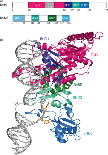
Min & Pavletich, (Reference Min and Pavletich2007) obtained the crystal structure of the yeast homolog of XPC–RAD23B (Rad4-Rad23, Fig. 5a ) in complex with a CPD lesion in a mismatched situation with two thymidines (Fig. 5b ). A shorter version of the protein (the DNA-binding domain) showing the same affinity to damaged DNA as the full length protein was crystallized. The crystal structure shows that Rad4 inserts a β-hairpin (beta hairpin domain 3, (BHD3)) into the destabilized DNA duplex, inducing the two damaged base pairs to completely flip out of the double helix (base flipping). A kink of 42° is created which could be confirmed by atomic force microscopy (Hwang et al. Reference Hwang, Ford, Hanawalt and Chu1999). The protein recognizes the expelled nucleotides of the undamaged strand through Van der Waals interactions with BHD1 and transglutaminase homology domain (TGD), while the two CPD-linked nucleotides are disordered in the structure and could not be resolved. The protein undergoes a conformational change during binding to damaged DNA (induced fit). The authors deduced from these findings that the lesions recognized by XPC must thermodynamically destabilize the Watson–Crick double helix in a manner that facilitates the flipping-out of two bases. The protein recognizes a weakened and distorted DNA helix without binding directly to the damage.
(a) Schematic representation of Rad4 and Rad23. The TGD domain is depicted in pink, BHD1 in dark blue, BHD2 in cyan, BHD3 in blue and R4BD in green. (b) Crystal structure of the yeast Rad4–Rad23 in complex with a CPD damaged DNA (PDB code: 2QSG) (Min & Pavletich, Reference Min and Pavletich2007). Same color code as in (a). The extruded Ts in front of the CPD lesion are depicted in orange.

The structure, however, does not explain why the CPD damage alone, without a mismatch, is so efficiently repaired by NER. For UV lesion repair, additional damage recognition factors must exist. New experiments show that the UV-DDB protein plays a very important role and that this protein recruits the XPC–RAD23B protein to the UV-damaged sites (Fitch et al. Reference Fitch, Nakajima, Yasui and Ford2003; Wakasugi et al. Reference Wakasugi, Kawashima, Morioka, Linn, Sancar, Mori, Nikaido and Matsunaga2002). Also the 6–4PP lesion which is a better NER substrate than CPD (Mitchell & Nairn, Reference Mitchell and Nairn1989), requires XPC–RAD23B as well as UV-DDB for recognition. See Section 2.
Camenisch et al. (Reference Camenisch, Trautlein, Clement, Fei, Leitenstorfer, Ferrando- May and Naegeli2009) proposed a two-stage detection process for XPC that recognizes DNA lesions without involvement of a DNA-binding domain (BHD3). BHD1/BHD2 and a β-turn subdomain act as a damage sensor that scans the double helix for unpaired bases, which forms a labile recognition complex. Subsequently, a stable recognition is formed through binding of BHD3 to the flipped out nucleotides in the undamaged strand across the lesion (Camenisch et al. Reference Camenisch, Trautlein, Clement, Fei, Leitenstorfer, Ferrando- May and Naegeli2009).
Chen et al. (Reference Chen, Velmurugu, Zheng, Park, Shim, Kim, Liu, Van Houten, He, Ansaria and Min2015) obtained the crystal structure of the yeast homolog of XPC–RAD23B (Rad4–Rad23) in complex with undamaged DNA using disulfide crosslinking. The crystal structure shows that Rad4 flips out normal nucleotide pairs like with damaged DNA. Therefore, structural discrimination of Rad4/XPC cannot play an important role for lesion recognition. The authors propose a ‘kinetic-gating’ mechanism for Rad4/XPC lesion recognition, which is controlled by two kinetic parameters (opening time and residence time). The weakened base stacking and hydrogen bonding within a lesion lead to a larger opening time for damaged DNA than for undamaged DNA to form a stable recognition complex. Also, the residence time is larger for damaged DNA indicating that Rad4/XPC opens damaged DNA with a higher probability (Chen et al. Reference Chen, Velmurugu, Zheng, Park, Shim, Kim, Liu, Van Houten, He, Ansaria and Min2015).
4. XPB
XPB (also called ERCC3) is a 3′–5′ ATP-dependent DNA helicase and a subunit of the TFIIH complex necessary for transcription and DNA repair (Gillet & Scharer, Reference Gillet and Scharer2006; Lehmann, Reference Lehmann2003; Schaeffer et al. Reference Schaeffer, Roy, Humbert, Moncollin, Vermeulen, Hoeijmakers, Chambon and Egly1993). Mutations in XPB lead to a 1000-fold increase of the melanoma risk and neurological abnormalities because of a defective TFIIH function in NER (Lehmann, Reference Lehmann2003). The human protein consists of 782 amino acids (89 kDa). NER helicases (XPB and XPD) all include conserved Rad51/RecA like ATPase domains called helicase domains 1 and 2 (HD1 and HD2), containing the ATPase and helicase motifs characteristic for superfamily 2 (SF2) helicases (Shin et al. Reference Shin, Pellegrini, Daniels, Yelent, Craig, Bates, Yu, Shivji, Hitomi, Arvai, Volkmann, Tsuruta, Blundell, Venkitaraman and Tainer2003; Story & Steitz, Reference Story and Steitz1992). Furthermore, NER helicases consist of two accessory domains, which are responsible for transmitting the helicase domain changes upon binding to DNA. The ATPase activity of XPB is necessary during NER to anchor TFIIH to the lesion site (Abdulrahman et al. Reference Abdulrahman, Iltis, Radu, Braun, Maglott-Roth, Giraudon, Egly and Poterszman2013; Coin et al. Reference Coin, Marinoni, Rodolfo, Fribourg, Pedrini and Egly1998; Dubaele et al. Reference Dubaele, Proietti De Santis, Bienstock, Keriel, Stefanini, Van Houten and Egly2003; Oksenych et al. Reference Oksenych, Bernardes de Jesus, Zhovmer, Egly and Coin2009). Its helicase activity is, however, not needed for the repair process (Coin et al. Reference Coin, Oksenych and Egly2007; Oksenych et al. Reference Oksenych, Bernardes de Jesus, Zhovmer, Egly and Coin2009; Tirode et al. Reference Tirode, Busso, Coin and Egly1999).
4.1 Crystal structure of Archaeglobus fulgidus XPB (AfXPB)
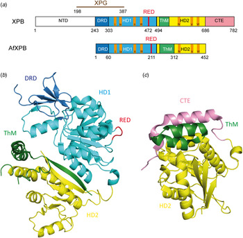
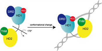
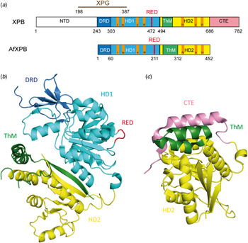
Fan et al. (Reference Fan, Arvai, Cooper, Iwai, Hanaoka and Tainer2006) determined the crystal structure of an A. fulgidus XPB homolog (AfXPB) with a sequence equivalent to residues 240–686 of the human XPB (Fig. 6b ). The AfXPB structure is built up by two Rad51/RecA-like helicase domains, HD1 and HD2, containing seven conserved helicase motifs (Walker motif I, Ia and II–VI) in the middle of the polypeptide (Fig. 6a ) (Fuss & Tainer, Reference Fuss and Tainer2011; Tuteja & Tuteja, Reference Tuteja and Tuteja1996). These domains use the binding and hydrolysis of ATP to induce conformational changes of the protein. Furthermore, the protein contains a DNA damage recognition domain (DRD), a unique RED motif (Arg–Glu–Asp) and a thumb domain (ThM). These domains are highly conserved and they are also found in the corresponding human protein. The structure suggests that the ATP hydrolysis provides the energy to induce a flip of about 170° in the orientation of HD2 relative to HD1 after DNA binding (Fig. 7). This conformational change brings the RED domain and the ThM domain in close vicinity and stabilizes TFIIH on the DNA by inserting a wedge (Glu473) into the double strand, gripped by the ThM domain. The motion might be important for melting the DNA duplex and anchoring TFIIH (Coin et al. Reference Coin, Oksenych and Egly2007). Mutations in the RED and ThM domains as well as mutations in the ATPase domain diminish the helicase activity, suggesting that these three domains ensure the correct recruitment of TFIIH to the damaged site.
(a) Schematic alignment of XPB and AfXPB showing the different domains: The DRD domain is depicted in blue, HD1 in light blue, HD1 in yellow, ThM in green and CTE (C-terminal extension) in pink. The conserved helicase motifs (Walker A motif I–VI) are depicted in orange. (b) Crystal structure of the AfXPB protein (PDB code: 2FWR). (Fan et al. Reference Fan, Arvai, Cooper, Iwai, Hanaoka and Tainer2006). Same color code as in (a). (c) Crystal structure of C-terminal domain of the human XPB protein (PDB code: 4ERN) (Hilario et al. Reference Hilario, Li, Nobumori, Liu and Fan2013). Same color code as in (a).
Proposed model for binding of XPB to DNA (adapted from Fan et al. (Reference Fan, Arvai, Cooper, Iwai, Hanaoka and Tainer2006)). The apo-protein is in an opened conformation. By binding to DNA, a rotation (170°) of the second helicase domain (HD2) together with the ThM domain, facilitated by HD1-mediated ATP hydrolysis, takes place and forms the closed and stable XPB–DNA complex. Same color code as in Fig. 6a .

4.2 Crystal structure of human XPB
Hilario et al. (Reference Hilario, Li, Nobumori, Liu and Fan2013) successfully solved the crystal structure of the C-terminal fragment of human XPB (residues 494–782) containing the helicase domain 2 (HD2), the thumb-like domain (ThM) and the C-terminal extension (Fig. 6c ). They investigated the structural basis for the role of the C-terminus of XPB in transcription and DNA repair. Because of lack of electron density in the structure, only the positions of the residues 502–730 could be determined. The observed structure consists of a globular domain containing a central sheet of seven parallel β-strands sandwiched by three α-helices on one side and two α-helices on the other (Fig. 6c ). The C-terminal extension (residues 670–730) is built up by two α-helices linked by a loop and a β-strand, which forms the edge strand of the seven-stranded central sheet, and an unstructured tail that possibly extends to the C-terminus. The ThM domain and one α-helix of the C-terminal extension are located at the top of the central sheet. Thus, the recruitment of TFIIH to the damage site is an active process controlled by the ATPase motif of XPB. This suggests that this subunit acts as an ATP-dependent hook that stabilizes the binding of the TFIIH to damaged DNA (Hilario et al. Reference Hilario, Li, Nobumori, Liu and Fan2013). In fact, a mutated ATPase activity of XPB abolishes the NER activity (Guzder et al. Reference Guzder, Sung, Bailly, Prakash and Prakash1994; Sung et al. Reference Sung, Higgins, Prakash and Prakash1988). Recruiting TFIIH to the damage site by the ATPase activity of XPB may reorganize the protein–DNA complexes in order to allow new protein–protein or protein–DNA contacts to happen.
5. XPD
The XPD (also called ERCC2) protein with a size of 87 kDa (760 amino acids) is known to be involved in transcription and DNA damage repair. It is a key subunit of the TFIIH complex and acts as an ATP-dependent 5′–3′ DNA helicase that belongs to the superhelicase 2 family (SF2) proteins (Araujo et al. Reference Araujo, Tirode, Coin, Pospiech, Syvaoja, Stucki, Hubscher, Egly and Wood2000; Coin et al. Reference Coin, Oksenych and Egly2007). The helicase activity of XPD is not required for transcription but is indispensable for the NER process (Winkler et al. Reference Winkler, Araujo, Fiedler, Vermeulen, Coin, Egly, Hoeijmakers, Wood, Timmers and Weeda2000). The TFIIH complex interacts with other NER factors such as XPA, XPC, XPG and XPF–ERCC1 (Evans et al. Reference Evans, Fellows, Coffer and Wood1997a; Gillet et al. Reference Gillet, Alzeer and Scharer2005). Mutations in human XPD lead to three different inherited diseases: XP, the CS and TTD. XPD is thought to be responsible for the damage verification (Mathieu et al. Reference Mathieu, Kaczmarek and Naegeli2010; Naegeli et al. Reference Naegeli, Modrich and Friedberg1993) before the recruitment of downstream NER factors to the lesion site occurs. This idea has been postulated based on the observation that the helicase activity of XPD becomes inhibited by the presence of DNA damage (Mathieu et al. Reference Mathieu, Kaczmarek and Naegeli2010, Reference Mathieu, Kaczmarek, Ruthemann, Luch and Naegeli2013; Naegeli et al. Reference Naegeli, Bardwell and Friedberg1992).
5.1 Crystal structure of Sulfolobus acidocaldarius XPD (SaXPD)
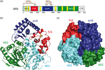
Several crystal structures of the catalytic domain of XPD from different organisms (S. acidocaldarius (Fan et al. Reference Fan, Fuss, Cheng, Arvai, Hammel, Roberts, Cooper and Tainer2008) (SaXPD; Fig. 8), Thermoplasma acidophilum (Wolski et al. Reference Wolski, Kuper, Hanzelmann, Truglio, Croteau, Van Houten and Kisker2008) (TaXPD) and Sulfolobus tokodaii (Liu et al. Reference Liu, Rudolf, Johnson, McMahon, Oke, Carter, McRobbie, Brown, Naismith and White2008)) reveal a four domain organization: a domain harboring the 4Fe4S iron–sulfur cluster (FeS domain), an arch domain and two canonical Rad51/RecA like domains, the helicase domains HD1 and HD2 (Fig. 8a ). The FeS domain is essential for the helicase activity of XPD.
(a) Schematic representation of human XPD (Fan et al. Reference Fan, Fuss, Cheng, Arvai, Hammel, Roberts, Cooper and Tainer2008). The protein interacts with XPGC (C-terminal domain of XPG) and XPGN (N-terminal domain of XPG) depicted in brown. (b) Crystal structure of SaXPD (PDB code: 3CRV) (Fan et al. Reference Fan, Fuss, Cheng, Arvai, Hammel, Roberts, Cooper and Tainer2008) with the HD1 domain (light blue) and the HD2 domain (green) form the ATP-binding interface. The arch domain is depicted in blue and FeS domain in red. The iron–sulfur cluster (4Fe4S) is depicted in orange and yellow. (c) Surface representation of SaXPD showing the tunnel formed by the different domains, which is large enough to pass through ssDNA.

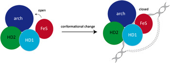
The different domains form a tunnel that is large enough to harbor ssDNA (Fig. 8b, c ) (Fan et al. Reference Fan, Fuss, Cheng, Arvai, Hammel, Roberts, Cooper and Tainer2008; Liu et al. Reference Liu, Rudolf, Johnson, McMahon, Oke, Carter, McRobbie, Brown, Naismith and White2008; Wolski et al. Reference Wolski, Kuper, Hanzelmann, Truglio, Croteau, Van Houten and Kisker2008). Fan et al. proposed a model of XPD binding to ssDNA (Fig. 9) (Fan et al. Reference Fan, Fuss, Cheng, Arvai, Hammel, Roberts, Cooper and Tainer2008). The iron–sulfur cluster is supposed to act as a molecular plough, which scans blocking damages by breaking hydrogen bonds (Lehmann, Reference Lehmann2008; White, Reference White2009). In this process, one strand of the duplex is supposed to be pulled through the internal channel with the help of the ATP-dependent motor domain, while damaged DNA will plug the channel (Fan et al. Reference Fan, Fuss, Cheng, Arvai, Hammel, Roberts, Cooper and Tainer2008; Liu et al. Reference Liu, Rudolf, Johnson, McMahon, Oke, Carter, McRobbie, Brown, Naismith and White2008; Mathieu et al. Reference Mathieu, Kaczmarek, Ruthemann, Luch and Naegeli2013; Pugh et al. Reference Pugh, Wu and Spies2012; Wolski et al. Reference Wolski, Kuper, Hanzelmann, Truglio, Croteau, Van Houten and Kisker2008). In this way, the protein undergoes a conformational change by closing the domain between the arch and the FeS motifs. The helicase domains HD1 and HD2 furnish the necessary flexibility for translocation (Fan et al. Reference Fan, Fuss, Cheng, Arvai, Hammel, Roberts, Cooper and Tainer2008).
DNA-binding model of SaXPD adapted from Fan et al. (Reference Fan, Fuss, Cheng, Arvai, Hammel, Roberts, Cooper and Tainer2008). The HD1 domain is depicted in light blue, the HD2 domain in green, the arch domain is depicted in blue, the FeS domain in red and the DNA in gray. Upon binding to the DNA the protein undergoes a conformational change by closing the domain between the arch and the FeS domains.

Because the channel is not narrow enough to distinguish between damaged and undamaged bases 2008, Wolski et al. proposed that during the unwinding process single bases are analyzed through insertion of the DNA backbone into a neighboring binding pocket on the protein surface. Damaged bases would not fit into the pocket, which could be the signal that leads to blocking of the helicase activity (Wolski et al. Reference Wolski, Kuper, Hanzelmann, Truglio, Croteau, Van Houten and Kisker2008).
5.2 Crystal structure of T. acidophilum (TaXPD) in complex with ssDNA
Finally, in 2012 Kuper et al. successfully solved the crystal structure of TaXPD in complex with a ssDNA oligonucleotide (22mer), shedding light on the mechanism of polarity and translocation of the protein along the DNA (Kuper et al. Reference Kuper, Wolski, Michels and Kisker2012). At the same time Pugh et al. showed that the 5′–3′ translocation polarity needs conserved residues in the HD1 and the FeS domains. They propose that the FeS domain provides a wedge-like feature enabling the duplex opening during unwinding (Pugh et al. Reference Pugh, Wu and Spies2012).
The structure allowed the Kisker group to define the translocation path of the DNA substrate through the protein and to determine the DNA-binding domain (DBD) of TaXPD by mutational and biochemical analysis. Only four bases (TACG) of the oligonucleotide could be identified in the electron density. These bases are located in the cleft of the HD2 domain (Fig. 10). This domain was already predicted as a potential binding cleft by Wolski et al. (Reference Wolski, Kuper, Hanzelmann, Truglio, Croteau, Van Houten and Kisker2008). The structure shows stacking of Trp549 with the adenine of TACG. Arg584 builds hydrogen bonds with N1 and N2 of the phosphate backbone of adenine and cytosine. Phe538 does not directly contact the DNA, but it is supposed to stabilize larger bases like adenine or guanine. A fourth residue Asp582 stabilizes Arg584 by hydrogen bonding to maintain it in position for DNA binding. The 5′ end points away from the HD2 domain and the 3′ end points towards HD1 domain. Kuper et al. propose a model (Fig. 10) which shows how the ssDNA is situated and translocated in the protein.
Crystal structure of Thermoplasma acidophilum XPD (TaXPD) in complex with a 10 nt ssDNA. The arch domain is depicted in dark blue, the FeS domain in red, the HD1 domain in cyan and the HD2 domain in green. The four bases (TACG), showing electron density, are depicted as gray sticks. The modeled ssDNA in the pore is schematically represented in gray. The modeled structure is adapted from Kuper et al. (Reference Kuper, Wolski, Michels and Kisker2012).

5.3 Proposed model of damage verification
Based on these new data about XPD, Fuss and Tainer proposed an extended model of the damage verification process, the so-called ‘bind-pry-unwind’-model: (Fuss & Tainer, Reference Fuss and Tainer2011) here XPB, XPD and CAK of the TFIIH complex are all considered to be essential for the coordination of damage recognition, verification, repair and signaling. In this model, the damage recognition proteins not only recruit the TFIIH complex and other NER factors to the damage site, but also fix the DNA at the same time. Kim et al. suggested that XPB facilitates the unwinding of the DNA duplex during transcription by distorting the DNA underneath the transcription bubble, which is fixed by the transcription factors and RNAP II (Kim et al. Reference Kim, Ebright and Reinberg2000). Similarly XPB could unwind and open the DNA. In that way, the damage verification step and the DNA unwinding could be linked. These findings are in accord with the low helicase activity of XPB and its strong conformational change upon binding to DNA (Fan et al. Reference Fan, Arvai, Cooper, Iwai, Hanaoka and Tainer2006). Furthermore, TFIIH can thereby position itself directly next to XPC–RAD23B or RNAP II, which establishes a common mechanism of how XPB may act in GG-NER, TC-NER and transcription. Through its short binding canal, XPB could place TFIIH vertically to the DNA and 5′ of the recognition protein. Then XPB could break the DNA strand, so that TFIIH bends it towards the DNA enabling XPD to bind about 22 base pairs away from the lesion on the damaged strand. Fuss and Tainer assume that the distance between XPB and XPD determines the size of the open DNA-bubble, corresponding to about 27 base pairs that are eliminated during NER. XPA catalyzes the release of CAK from the TFIIH complex (Coin et al. Reference Coin, Oksenych, Mocquet, Groh, Blattner and Egly2008). This step signals that the repair process can be continued and promotes the incision step. The XPD helicase unwinds the duplex until the 4Fe4S-cluster docks onto the damage and is blocked by it (Mathieu et al. Reference Mathieu, Kaczmarek and Naegeli2010; Naegeli et al. Reference Naegeli, Modrich and Friedberg1993). Recent studies show that XPD exists in different conformations depending on the type of damage (Buechner et al. Reference Buechner, Heil, Michels, Carell, Kisker and Tessmer2014). After the blockage, XPD and XPC–RAD23B anchor the TFIIH complex and build a platform for binding of ERCC1-XPF and XPG (Araujo et al. Reference Araujo, Nigg and Wood2001).
Following this model RPA, XPA and XPG probably reach the lesion site independently and build together with TFIIH the pre-incision complex (Rademakers et al. Reference Rademakers, Volker, Hoogstraten, Nigg, Mone, Van Zeeland, Hoeijmakers, Houtsmuller and Vermeulen2003; Riedl et al. Reference Riedl, Hanaoka and Egly2003; Volker et al. Reference Volker, Mone, Karmakar, van Hoffen, Schul, Vermeulen, Hoeijmakers, van Driel, van Zeeland and Mullenders2001; Wakasugi & Sancar, Reference Wakasugi and Sancar1998). Here, all NER factors, except ERCC1-XPF, are present and stably bound to the open DNA bubble.
Recently, the Kisker group showed by mutational analysis that the FeS domain of XPD is crucial for NER (Kuper et al. Reference Kuper, Braun, Elias, Michels, Sauer, Schmitt, Poterszman, Egly and Kisker2014). Furthermore, the successful repair process is dependent on the enzymatic activities of XPD which involves DNA binding, ATPase activity, helicase activity and the correct interaction with other TFIIH subunits. In 2013, the Naively group showed by uncoupling the DNA unwinding activity from the damage verification activity of XPD, that residues Tyr192 and Arg196 form a sensor pocket located ahead of the narrow central protein pore responsible for damage recognition. By mutating these two residues, the helicase and ATPase activities are not affected but the damage sensing during ATP-driven scanning movement along nucleic acid lattices fails and the ability of XPD to form stable DNA damage recognition intermediates is significantly reduced (Mathieu et al. Reference Mathieu, Kaczmarek, Ruthemann, Luch and Naegeli2013). The activity of XPD however is not relevant for transcription and DNA binding.
6. XPA
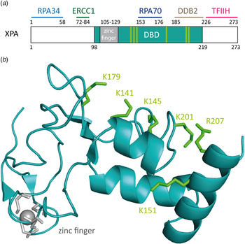
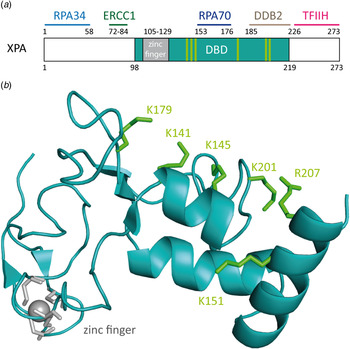
The XPA protein (xeroderma pigmentosum group complementation group A) consists of 273 amino acids (31 kDa) and can occur as either a homodimer or in complex with other NER proteins (Liu et al. Reference Liu, Yang, Utzat, Wang, Basu and Zou2005; Yang et al. Reference Yang, Liu, Mao, Zhang and Zou2002). The protein is constituted of several domains (Camenisch et al. Reference Camenisch, Dip, Schumacher, Schuler and Naegeli2006; Camenisch & Nägeli, Reference Camenisch and Nägeli2008): the N-terminal domain (XPA4–97) includes the RPA34- and ERCC1-binding regions (He et al. Reference He, Henricksen, Wold and Ingles1995; Li et al. Reference Li, Lu, Peterson and Legerski1995a). The C-terminal domain (XPA226–273) interacts with TFIIH (Camenisch & Nägeli, Reference Camenisch and Nägeli2008; Ikegami et al. Reference Ikegami, Kuraoka, Saijo, Kodo, Kyogoku, Morikawa, Tanaka and Shirakawa1998; Park et al. Reference Park, Bessho, Matsunaga and Sancar1995a). The central domain (XPA98–219) is the minimal DBD (XPA-DBD) (Cleaver & States, Reference Cleaver and States1997; Kuraoka et al. Reference Kuraoka, Morita, Saijo, Matsuda, Morikawa, Shirakawa and Tanaka1996). The protein contains a zinc-finger binding domain (Cys105-X2-Cys108-X17-Cys126-X2-Cys129) (Hess et al. Reference Hess, Buchko, Conradson, Espinosa, Ni, Thrall and Kennedy1998). The C4–zinc finger sustains the stability of the protein and plays a role in the interaction with RPA70 (Fig. 11a ) (Ikegami et al. Reference Ikegami, Kuraoka, Saijo, Kodo, Kyogoku, Morikawa, Tanaka and Shirakawa1998; Kuraoka et al. Reference Kuraoka, Morita, Saijo, Matsuda, Morikawa, Shirakawa and Tanaka1996; Morikawa & Shirakawa, Reference Morikawa and Shirakawa2000; Morita et al. Reference Morita, Ohkubo, Kuraoka, Shirakawa, Tanaka and Morikawa1996; Sugitani et al. Reference Sugitani, Shell, Soss and Chazin2014). Mutation of one or all zinc-binding cysteines leads to a loss of function of XPA and to an almost complete loss of function of NER (Li et al. Reference Li, Peterson, Lu and Legerski1995b; Mellon et al. Reference Mellon, Spivak and Hanawalt1987).
(a) Schematic view of the human XPA protein with XPA–DBD (DNA-binding domain, XPA98-219) in cyan the zinc-finger domain in gray. The binding domains of XPA with other NER proteins are depicted in light blue for RPA34, green for ERCC1, dark blue for RPA70 and pink for TFIIH. (b) NMR-structure of the XPA–DBD (Buchko et al. Reference Buchko, Tung, McAteer, Isern, Spicer and Kennedy2001; Camenisch et al. Reference Camenisch, Dip, Schumacher, Schuler and Naegeli2006; Ikegami et al. Reference Ikegami, Kuraoka, Saijo, Kodo, Kyogoku, Morikawa, Tanaka and Shirakawa1998) (PDB code: 1XPA). Positively charged amino acids that build the cleft are depicted as green sticks. The zinc atom is shown in gray.
It has been demonstrated that XPA binds ssDNA, dsDNA and denaturated stretches of DNA in cooperation with RPA (Buschta-Hedayat et al. Reference Buschta-Hedayat, Buterin, Hess, Missura and Naegeli1999; Missura et al. Reference Missura, Buterin, Hindges, Hubscher, Kasparkova, Brabec and Naegeli2001; Wang et al. Reference Wang, Mahrenholz and Lee2000; Yang et al. Reference Yang, Roginskaya, Colis, Basu, Shell, Liu, Musich, Harris, Harris and Zou2006). XPA shows binding affinity to irradiated DNA (Jones & Wood, Reference Jones and Wood1993; Liu et al. Reference Liu, Yang, Utzat, Wang, Basu and Zou2005), DNA containing bulky adducts and cisplatin lesions (Jones & Wood, Reference Jones and Wood1993; Liu et al. Reference Liu, Yang, Utzat, Wang, Basu and Zou2005), as well as to DNA duplexes containing loops and bulges (Camenisch et al. Reference Camenisch, Dip, Schumacher, Schuler and Naegeli2006). Camenisch et al. could show by mutational analyses that the residues Lys141 and Lys179 found on the surface of XPA next to the DNA-binding pocket are responsible for the sensing of DNA deformability as the common characteristics of damaged sites (Camenisch et al. Reference Camenisch, Dip, Schumacher, Schuler and Naegeli2006; Miyamoto et al. Reference Miyamoto, Miura, Niwa, Miyazaki and Tanaka1992). It was postulated that these two lysines interact with the DNA backbone, when XPA is in complex with RPA and kinked DNA (Read et al. Reference Read, Cary, Crane-Robinson, Driscoll and Norman1993; Weir et al. Reference Weir, Kraulis, Hill, Raine, Laue and Thomas1993). Photocrosslinking experiments demonstrated that the mutated protein does interact with kinked DNA structures (Camenisch et al. Reference Camenisch, Dip, Schumacher, Schuler and Naegeli2006). This led to the assumption that the protein scans the DNA duplex for the presence of the kinked DNA structure with its positively charged pocket. The loop-rich domain of XPA was determined to be responsible for DNA binding. The ternary structure is stabilized by the zinc-finger domain (Miyamoto et al. Reference Miyamoto, Miura, Niwa, Miyazaki and Tanaka1992; Yan et al. Reference Yan, Yuan, Velculescu, Vogelstein and Kinzler2002).
6.1 Nuclear magnetic resonance (NMR) structure of the DBD of human XPA
Ikegami et al. (Reference Ikegami, Kuraoka, Saijo, Kodo, Kyogoku, Morikawa, Tanaka and Shirakawa1998) determined the NMR structure of the DBD of XPA (XPA98–219, called XPA-DBD) and they found that the protein contains α-helices and β-sheets (Fig. 11b ). The structure shows the presence of a positively charged (basic amino acids) cleft with the right dimension to bind dsDNA (Buchko et al. Reference Buchko, Ni, Thrall and Kennedy1998, Reference Buchko, Tung, McAteer, Isern, Spicer and Kennedy2001). This positively charged cleft was speculated to interact with the negatively charged DNA backbone.
Sugitani et al. (Reference Sugitani, Shell, Soss and Chazin2014) redefined the DBD of XPA. By extending the originally characterized XPD-DBD at its C-terminus by 20 amino acids (XPA98–239), they improved the DNA-binding properties. The new construct with the additional critical basic residues and helical elements at its C-terminus was found to bind to DNA substrates with the same affinity as the full-length protein. The group reported, based on NMR data, that XPA98–239 contains the same globular core as XPA98−219 and similarly undergoes a conformational change when binding to Y-shaped ss/ds-DNA junctions.
The rather small XPA protein interacts with a large number of other NER factors which supports its function as a scaffold protein for the assembly of the incision complex during repair (Gillet & Scharer, Reference Gillet and Scharer2006; Naegeli & Sugasawa, Reference Naegeli and Sugasawa2011). Probably, XPA binds best to already prekinked DNA structures, which explains why XPA is able to bind defect Watson–Crick base pairing, created by mismatches, bubbles or three-way junctions (Bootsma & Hoeijmakers, Reference Bootsma and Hoeijmakers1993; Buschta-Hedayat et al. Reference Buschta-Hedayat, Buterin, Hess, Missura and Naegeli1999; Missura et al. Reference Missura, Buterin, Hindges, Hubscher, Kasparkova, Brabec and Naegeli2001). These structures can form easily kinked DNA structures. XPA shows a slight binding preference to UV-damaged DNA and bulky adducts over undamaged DNA (Jones & Wood, Reference Jones and Wood1993; Robins et al. Reference Robins, Jones, Biggerstaff, Lindahl and Wood1991; Thoma & Vasquez, Reference Thoma and Vasquez2003). Similarly to XPC, XPA recognizes 6–4PP lesions but not CPDs (Jones & Wood, Reference Jones and Wood1993). CPD might block the bending of major grooves because of its stiff four-membered ring which points into the major groove. XPA shows a high affinity to DNA containing aromatic adducts and cisplatin crosslinks. Cisplatin crosslinks also kink the DNA structure. The damage recognition capability of XPA increases with RPA (Jones & Wood, Reference Jones and Wood1993; Li et al. Reference Li, Lu, Peterson and Legerski1995a; Mellon et al. Reference Mellon, Spivak and Hanawalt1987) and ERCC1 (Nocentini et al. Reference Nocentini, Coin, Saijo, Tanaka and Egly1997; Saijo et al. Reference Saijo, Kuraoka, Masutani, Hanaoka and Tanaka1996). XPA does not bind ssDNA, in agreement with the observed size of the positively charged cleft able to fit dsDNA (Buchko et al. Reference Buchko, Ni, Thrall and Kennedy1998; Ikegami et al. Reference Ikegami, Kuraoka, Saijo, Kodo, Kyogoku, Morikawa, Tanaka and Shirakawa1998). For single-base bulky adduct lesions such as AAF-dG, it is unclear to which extent they prekink the duplex. Bulky adducts can increase the local conformational flexibility of DNA (Isaacs & Spielmann, Reference Isaacs and Spielmann2004). XPA might employ a DNA flexibility scanning mechanism to create a kink, which could be stabilized by intercalation of the aromatic ring into the duplex and may be the secret behind the broad substrate promiscuity of NER. Koch et al. could obtain two crystal structures of Rad14 with a bulky lesion, which confirm this hypothesis (Koch et al. Reference Koch, Kuper, Gasteiger, Simon, Strasser, Eisen, Geiger, Schneider, Kisker and Carell2015).
6.2 Crystal structures of Rad14 with AAF-dG and cisplatin containing dsDNA
Recently, Koch et al. (Reference Koch, Kuper, Gasteiger, Simon, Strasser, Eisen, Geiger, Schneider, Kisker and Carell2015) solved two crystal structures of the yeast homolog of XPA (Rad14) in complex with AAF-dG and 1,2-GG cisplatin containing DNA (Fig. 12b, c ). The DBD of the protein (residues 188–306) was crystallized with damaged DNA (Fig. 12a ). The structures allow us to uncover the molecular mechanism of XPA interacting with damaged DNA and are consistent with previous biochemical data showing the binding of XPA to kinked DNA structures (Buschta-Hedayat et al. Reference Buschta-Hedayat, Buterin, Hess, Missura and Naegeli1999; Camenisch et al. Reference Camenisch, Dip, Schumacher, Schuler and Naegeli2006). The protein assumes an overall α/β-fold quite similar to its human homolog (Ikegami et al. Reference Ikegami, Kuraoka, Saijo, Kodo, Kyogoku, Morikawa, Tanaka and Shirakawa1998; Koch et al. Reference Koch, Kuper, Gasteiger, Simon, Strasser, Eisen, Geiger, Schneider, Kisker and Carell2015). Comparable with Rad4, Rad14 does not bind the lesion directly; instead it recognizes a weakened DNA duplex structure (Min & Pavletich, Reference Min and Pavletich2007). By the binding of two Rad14 proteins to the duplex, the DNA undergoes a sharp kink of 70° at the lesion site and single stranded regions are formed above and below the 13mer binding motif. Through insertion of a β-hairpin (His258 and Phe262) from each protein (acting like ‘fingers’) exactly six base pairs away from the lesion, a 13mer recognition motif is generated. Another domain composed of helix α7 (‘thumb’ containing Arg234 and Arg239) interacts with the DNA backbone close to the lesion, so that DNA bending takes place into the major groove. The lesion is located inside the 13mer duplex instead of being flipped out. Because of the relatively few interactions between Rad14 and the duplex, the protein might preferably bind already pre-kinked DNA structures (Camenisch et al. Reference Camenisch, Dip, Schumacher, Schuler and Naegeli2006). The 2:1 complex can coordinate contacts between TFIIH, DNA and RPA and recruit ERCC1–XPF (Li et al. Reference Li, Lu, Peterson and Legerski1995a; Park et al. Reference Park, Mu, Reardon and Sancar1995b; Tripsianes et al. Reference Tripsianes, Folkers, Zheng, Das, Grinstead, Kaptein and Boelens2007).
(a) Schematic sequence of Rad14 with the DBD depicted in green, the zinc-finger domain in gray and the residues interacting with the DNA in orange and pink. (b) Crystal structure of Rad14 in complex with AAF-dG crosslinked DNA (PDB code: 5A3D) (Koch et al. Reference Koch, Kuper, Gasteiger, Simon, Strasser, Eisen, Geiger, Schneider, Kisker and Carell2015). Same color code as in (a). The AAF-dG residue is depicted in dark blue. (c) Crystal structure of Rad14 in complex with 1,2-GG cisplatin (PDB code: 5A39) (Koch et al. Reference Koch, Kuper, Gasteiger, Simon, Strasser, Eisen, Geiger, Schneider, Kisker and Carell2015). Same color code as in (a). The 1,2-GG cisplatin crosslink is depicted in dark blue.

7. XPF–ERCC1
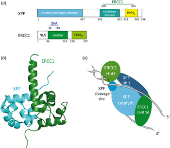
The human DNA repair endonuclease XPF (gene called ERCC4) is a protein of 916 amino acids (104 kDa) (Brookman et al. Reference Brookman, Lamerdin, Thelen, Hwang, Reardon, Sancar, Zhou, Walter, Parris and Thompson1996). It forms a stable ERCC1–XPF heterodimer enzyme complex that participates in DNA repair and DNA recombination (Sijbers et al. Reference Sijbers, de Laat, Ariza, Biggerstaff, Wei, Moggs, Carter, Shell, Evans, de Jong, Rademakers, de Rooij, Jaspers, Hoeijmakers and Wood1996; Tsodikov et al. Reference Tsodikov, Enzlin, Scharer and Ellenberger2005). ERCC1 is a protein of 297 amino acids (32.5 kDa) that mediates DNA–protein and protein–protein interactions. The XPF–ERCC1 complex cuts specific structures near an ss/dsDNA junction at the 5′-end of single stranded damaged DNA strand and hence makes the first incision in the NER process. Its nuclease activity is absolutely essential in the NER process (de Laat et al. Reference de Laat, Jaspers and Hoeijmakers1999; Sijbers et al. Reference Sijbers, de Laat, Ariza, Biggerstaff, Wei, Moggs, Carter, Shell, Evans, de Jong, Rademakers, de Rooij, Jaspers, Hoeijmakers and Wood1996). In the complex, XPF provides the endonuclease active site and is involved in DNA binding and establishing additional protein–protein interactions. XPF–ERCC1 is known to be the last factor joining the NER complex before dual incision takes place (Riedl et al. Reference Riedl, Hanaoka and Egly2003; Volker et al. Reference Volker, Mone, Karmakar, van Hoffen, Schul, Vermeulen, Hoeijmakers, van Driel, van Zeeland and Mullenders2001; Wakasugi & Sancar, Reference Wakasugi and Sancar1998). Evidence exists that it is recruited by XPA (Fig. 13a ) (Li et al. Reference Li, Elledge, Peterson, Bales and Legerski1994, Reference Li, Lu, Peterson and Legerski1995a ; Park & Sancar, Reference Park and Sancar1994; Saijo et al. Reference Saijo, Kuraoka, Masutani, Hanaoka and Tanaka1996).
(a) Structural domains of the human XPF and ERCC1 proteins. XPF interacts with ERCC1 (residues 670–895) depicted in green. The inactive helicase domain is depicted in light blue, the nuclease domain in cyan and the HhH2 domain in yellow. ERCC1 interacts with XPA (residues 99–118) depicted in dark blue. The central domain is depicted in green and the HhH2 domain in light green. (b) Structure of the human XPF–ERCC1 heterodimer (PDB code: 2A1J) (Tsodikov et al. Reference Tsodikov, Enzlin, Scharer and Ellenberger2005) with ERCC1 depicted in green and XPF depicted in light blue. (c) Model of the XPF–ERCC1 complex binding to a splayed DNA substrate (depicted in gray). The ERCC1 central domain and HhH domain are depicted in green. XPF, XPF cleavage site and HhH domain are depicted in light blue.
7.1 Crystal structure of human XPF–ERCC1
Tsodikov et al. (Reference Tsodikov, Enzlin, Scharer and Ellenberger2005) solved the crystal structure of the minimal dimerization domains of the human XPF and ERCC1 (Fig. 13b ). The crystallized domain shows a similar endonuclease activity compared to that of the full-length complex. Both protein domains exhibit double helix–hairpin–helix motifs (HhH2) related by a pseudo-2-fold symmetry axis (Tripsianes et al. Reference Tripsianes, Folkers, Ab, Das, Odijk, Jaspers, Hoeijmakers, Kaptein and Boelens2005). The HhH2 motifs are known to be ds- as well as ss-DNA-binding motifs (Newman et al. Reference Newman, Murray-Rust, Lally, Rudolf, Fadden, Knowles, White and McDonald2005; Singh et al. Reference Singh, Folkers, Bonvin, Boelens, Wechselberger, Niztayev and Kaptein2002). Both C-terminal HhH2 domains of XPF and ERCC1 are essential and sufficient for a stable heterodimer formation (de Laat et al. Reference de Laat, Appeldoorn, Sugasawa, Weterings, Jaspers and Hoeijmakers1998). XPF might play a role as a scaffold protein, allowing proper folding of the ERCC1 domain. All XPF family members contain a catalytic domain comprising the active site motive (GDX n ERKX3D) and they need a divalent cation for their nuclease activity (Nishino et al. Reference Nishino, Komori, Ishino and Morikawa2003; Sijbers et al. Reference Sijbers, de Laat, Ariza, Biggerstaff, Wei, Moggs, Carter, Shell, Evans, de Jong, Rademakers, de Rooij, Jaspers, Hoeijmakers and Wood1996).
7.2 NMR structure of C-terminal human XPF in complex with ssDNA
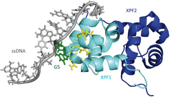
Das et al. (Reference Das, Folkers, van Dijk, Jaspers, Hoeijmakers, Kaptein and Boelens2012) solved the NMR structure of the C-terminal domain of the human XPF protein (residues 823–905) in complex with a 10-nucleotide ssDNA fragment. In earlier NMR studies of the apo-protein, the group showed that the XPF homodimer complex is more stable than the XPF–ERCC1 heterodimer complex (Das et al. Reference Das, Tripsianes, Jaspers, Hoeijmakers, Kaptein, Boelens and Folkers2008). The structure shows that a positively charged region of one HhH domain interacts with the ssDNA phosphate backbone. The central guanine (G5) is extruded from the duplex and inserted into a pocket formed by residues from both HhH motifs of XPF (Das et al. Reference Das, Tripsianes, Jaspers, Hoeijmakers, Kaptein, Boelens and Folkers2008; Tripsianes et al. Reference Tripsianes, Folkers, Ab, Das, Odijk, Jaspers, Hoeijmakers, Kaptein and Boelens2005). This cavity offers a large interaction surface area for the protein with the DNA. The DNA forms a right-handed structure binding to the protein, which mainly interacts with the ssDNA phosphate backbone (Fig. 14). In addition, the protein interacts with three bases: thymidine3 (His857), thymidine4 (Ser875, Ile876) and G5 (Leu877, Gly878 and Asn879). Combined with previous data (Tripsianes et al. Reference Tripsianes, Folkers, Ab, Das, Odijk, Jaspers, Hoeijmakers, Kaptein and Boelens2005) the group proposes a binding model of XPF–ERCC1 to ss/dsDNA junctions (Das et al. Reference Das, Folkers, van Dijk, Jaspers, Hoeijmakers, Kaptein and Boelens2012). They modeled the XPF–ERCC1 complex bound to a splayed-arm DNA substrate showing that the conserved HhH domain of ERCC1 contacts the phosphate backbone of dsDNA in the minor grove with its two hairpins H1 and H2 while the XPF HhH domain stabilizes the ssDNA via interactions with a 5′/3′ polarity (Fig. 13c ). The damaged strand gets cleaved by the catalytic residues of the XPF nuclease domain and the ERCC1 central domain connects with XPA and ssDNA on the NER complex (de Laat et al. Reference de Laat, Appeldoorn, Sugasawa, Weterings, Jaspers and Hoeijmakers1998).
NMR structure of the C-terminal domain of human XPF in complex with an ssDNA fragment (PDB code: 2KN7) (Das et al. Reference Das, Folkers, van Dijk, Jaspers, Hoeijmakers, Kaptein and Boelens2012). The first XPF (XPF1) protein is depicted in light blue showing the interacting residues with the DNA in yellow. The second XPF (XPF2) protein is depicted in light blue. The central guanine (G5) is depicted in green.

8. XPG
XPG (gene called ERCC5) is a single-stranded structure-specific DNA 3′-endonuclease involved in NER. It belongs to the family of FEN-1 endonucleases (Flap endonuclease) (Lieber, Reference Lieber1997). The human protein consists of 1186 amino acids (133 kDa) (O'Donovan et al. Reference O'Donovan, Scherly, Clarkson and Wood1994b) and it interacts with several other NER proteins (Fig. 15). Mutations in this gene cause the XP-G phenotype, characterized by hypersensitivity to UV light and increased susceptibility for skin cancer development following UV exposure. Furthermore, it can lead to the CS characterized by severe growth defects and mental retardation (Constantinou et al. Reference Constantinou, Gunz, Evans, Lalle, Bates, Wood and Clarkson1999). The XPG protein cleaves DNA near junctions of dsDNA to ssDNA with a defined polarity moving 3′–5′ away from the junction. It has been observed that XPG needs a duplex opening of more than five base pairs for efficient cleavage (Evans et al. Reference Evans, Fellows, Coffer and Wood1997a). The protein is known to interact with XPB, XPD, RPA and PCNA (Feltes & Bonatto, Reference Feltes and Bonatto2015; Iyer et al. Reference Iyer, Reagan, Wu, Canagarajah and Friedberg1996). XPG is needed for the proper recruitment of XPF–ERCC1 to the preincision complex. Once the 5′-incision is made by the XPF–ERCC1 nuclease, XPG becomes fully active (Staresincic et al. Reference Staresincic, Fagbemi, Enzlin, Gourdin, Wijgers, Dunand-Sauthier, Giglia-Mari, Clarkson, Vermeulen and Scharer2009). Despite this knowledge, the exact mechanism of substrate recognition by XPG is still unclear.
Schematic representation of human XPG with its different domains and the region interacting with other NER proteins. The D1 box is depicted in light green, the D2 box in green and the 600 aa spacer region in orange. The XPB and XPD interacting region is highlighted in purple, RPA interacting region in dark blue and the PCNA interacting region in pink. Glu791 and Asp812 in the active sites are depicted as light blue bars.

The human protein possesses a globular structure like the FEN-1 endonuclease (Hosfield et al. Reference Hosfield, Mol, Shen and Tainer1998; Hwang et al. Reference Hwang, Baek, Kim and Cho1998b). It contains an N-terminal domain and an I-region linked by a 600 residue long spacer region (Dunand-Sauthier et al. Reference Dunand-Sauthier, Hohl, Thorel, Jaquier-Gubler, Clarkson and Scharer2005; Hohl et al. Reference Hohl, Dunand-Sauthier, Staresincic, Jaquier-Gubler, Thorel, Modesti, Clarkson and Scharer2007). The N-terminal and the I-region are evolutionary conserved among similar endonucleases (T4 RNaseH, Taq Polymerase). The spacer region is not involved in catalysis. It is responsible for proper DNA cleavage and for the recruitment and positioning of XPG to the lesion site (Constantinou et al. Reference Constantinou, Gunz, Evans, Lalle, Bates, Wood and Clarkson1999; Dunand-Sauthier et al. Reference Dunand-Sauthier, Hohl, Thorel, Jaquier-Gubler, Clarkson and Scharer2005; He et al. Reference He, Henricksen, Wold and Ingles1995; Thorel et al. Reference Thorel, Constantinou, Dunand-Sauthier, Nouspikel, Lalle, Raams, Jaspers, Vermeulen, Shivji, Wood and Clarkson2004). It is also known to interact with RPA and TFIIH. The protein contains a D1 box (residues 184–210) and a D2 box (residues 890–984) which are evolutionary conserved (Dunand-Sauthier et al. Reference Dunand-Sauthier, Hohl, Thorel, Jaquier-Gubler, Clarkson and Scharer2005; Houle & Friedberg, Reference Houle and Friedberg1999). One cation is required for the endonuclease activity in the active site. The protein shows a higher affinity for Mn2+ than for Mg2+ and uses the more abundant one for catalysis (Hohl et al. Reference Hohl, Dunand-Sauthier, Staresincic, Jaquier-Gubler, Thorel, Modesti, Clarkson and Scharer2007; Iyer et al. Reference Iyer, Reagan, Wu, Canagarajah and Friedberg1996). Two residues in the active site (Glu791 and Asp812) coordinate the divalent cations (Constantinou et al. Reference Constantinou, Gunz, Evans, Lalle, Bates, Wood and Clarkson1999) (light blue sticks in Fig. 15). The protein incises flap DNA and bubbled DNA structures with a defined polarity (Evans et al. Reference Evans, Moggs, Hwang, Egly and Wood1997b; Hohl et al. Reference Hohl, Thorel, Clarkson and Scharer2003; O'Donovan et al. Reference O'Donovan, Davies, Moggs, West and Wood1994a; Tsutakawa et al. Reference Tsutakawa, Classen, Chapados, Arvai, Finger, Guenther, Tomlinson, Thompson, Sarker, Shen, Cooper, Grasby and Tainer2011).
8.1 Crystal structure of the yeast XPG (Rad2) in complex with dsDNA
To understand the mechanism of DNA binding by XPG Mietus et al. (Reference Mietus, Nowak, Jaciuk, Kustosz, Studnicka and Nowotny2014) solved in 2014 the crystal structure of the catalytic core of the Saccharomyces cerevisiae homolog of XPG (Rad2-ΔSC, Fig. 16a ) in complex with four different DNA substrates. For crystallization a XPG variant missing the mostly disordered spacer residues 111–730 between the two sequence segments N and I of the nuclease domain was used. The double-stranded oligonucleotides (12–15 bp) were designed with single-stranded overhangs constructed with one to six adenines or thymidines. In the crystal structure two Rad2 proteins bind to one DNA substrate with a single-protein molecule covering 13 bp of the double-stranded portion. Rad2 utilizes three structural domains to recognize the double-stranded portion of the DNA but it does not specifically recognize the single-stranded portion of the duplex. The structures reveal that the protein recognizes a single 5′-nucleotide of the single-stranded portion of the DNA and a 3′-phosphate group of the ds/ssDNA junction. The helix two turn helix (H2TH) motif including a Rad2-specific α-helix 12b and a hydrophobic wedge, which binds the first base pair of the double-stranded portion of the DNA, is responsible for binding to DNA. The helical arch may assume a different structure in Rad2 because its active site is more accessible compared with related enzymes such as FEN1 and EXO1 (Mietus et al. Reference Mietus, Nowak, Jaciuk, Kustosz, Studnicka and Nowotny2014). This feature allows the protein to form a gap and create an exit route from the active site. As expected, the catalytic core of Rad2 is quite comparable with other flap nucleases (Orans et al. Reference Orans, McSweeney, Iyer, Hast, Hellinga, Modrich and Beese2011). The protein has an oblong shape with its active site situated in the middle. A twisted central β-sheet composed of seven strands flanked by α-helices build the central core of the protein (Fig. 16b ). Gln37 forms a hydrogen bond with the base of the cleaved strand and represents an important residue of substrate recognition by Rad2. The H2TH module is responsible for the key protein–DNA interactions through its Rad2-specific helix α12b and the hydrophobic wedge contacting the ss/dsDNA junction.
Crystal structure of the Rad2–DNA complex (PDB code: 4Q0W) (Mietus et al. Reference Mietus, Nowak, Jaciuk, Kustosz, Studnicka and Nowotny2014). (a) Schematic representation of the protein. The hydrophobic wedge is depicted in green, the helical arch in red, the H2TH domain in light blue and the rest of the crystallized structure in dark blue. (b) Structure of Rad2 with dsDNA. Same color code as in (a). Calcium is depicted in light green and potassium in purple. The helix 12b is named as referred by Tsutakawa et al. (Reference Tsutakawa, Classen, Chapados, Arvai, Finger, Guenther, Tomlinson, Thompson, Sarker, Shen, Cooper, Grasby and Tainer2011). The spacer region omitted in the crystal structure is depicted as a yellow dashed line.

9. XPV
The repair of lesions by NER is a powerful method to clean the genome from the plethora of lesions that are generated daily. NER is hence the prime pathway that allows cells to cope with DNA damage. Because lesions can occur at any time in cellular DNA, even when the NER complex cannot assemble properly, e.g. while the cell is undergoing cell division, a second system has evolved that allows cells to cope with lesions. This system does not repair lesions but is able to give cells the ability to tolerate lesions, so that repair can be shifted to later times. This lesion tolerance process (called TLS) requires the action of special lesion tolerance polymerases. Among them the polymerase ɳ (XPV) is of prime importance, because it provides tolerance of dinucleotide lesions such as CPDs and cisplatin adducts, which are the prime repair targets for NER. XPV (Polymerase ɳ) is a Y-family DNA polymerase responsible for TLS enabling replication through bulky DNA adducts like cisplatin, UV-induced CPDs and 6–4PP as well as acetylaminofluorene adducts and oxidative lesions (like 8-oxo-G) (Alt et al. Reference Alt, Lammens, Chiocchini, Lammens, Pieck, Kuch, Hopfner and Carell2007; Biertumpfel et al. Reference Biertumpfel, Zhao, Kondo, Ramon-Maiques, Gregory, Lee, Masutani, Lehmann, Hanaoka and Yang2010; Haracska et al. Reference Haracska, Yu, Johnson, Prakash and Prakash2000; Reissner et al. Reference Reissner, Schneider, Schorr and Carell2010; Schorr et al. Reference Schorr, Schneider, Lammens, Hopfner and Carell2010b; Silverstein et al. Reference Silverstein, Jain, Johnson, Prakash, Prakash and Aggarwal2010a, Reference Silverstein, Johnson, Jain, Prakash, Prakash and Aggarwalb). The human protein consists of 713 amino acids with a size of 78 kDa (Masutani et al. Reference Masutani, Araki, Yamada, Kusumoto, Nogimori, Maekawa, Iwai and Hanaoka1999a). Indeed, mutation in the XPV gene leads to just another form of XP called the variant type also associated with a high risk of developing skin cancer (Johnson et al. Reference Johnson, Washington, Haracska, Prakash and Prakash2000; Lehmann et al. Reference Lehmann, Kirk-Bell, Arlett, Paterson, Lohman, de Weerd-Kastelein and Bootsma1975; Masutani et al. Reference Masutani, Kusumoto, Yamada, Dohmae, Yokoi, Yuasa, Araki, Iwai, Takio and Hanaoka1999b). Lesion tolerance, however, has a major drawback. Because the polymerases are able to read through lesions they also have a strongly reduced replication fidelity, which gives rise to mutations. That is why repair is always the first and preferred defense pathway.
9.1 Crystal structure of the yeast XPV (Rad30) protein
Kondratick et al. (Reference Kondratick, Washington, Prakash and Prakash2001) solved the crystal structure of the catalytic core (1–513 amino acids) of the S. cerevisiae apo-enzyme (Fig. 17b ). The catalytic core possesses the same bypass activity as the full-length protein (1–632 amino acids). The structure shows that the polymerase possesses a right-hand shape built up by four domains: thumb, fingers, PAD-domain (polymerase-associated domain also named ‘little fingers’ (LF)) and the palm domain (Fig. 17a ). Characterized by a wide open and possibly flexible active site, the polymerase is able to replicate over bulky dinucleotide lesions, however, at the cost of misincorporation and only a low processivity in contrast to high-fidelity polymerases. Because of the helix deforming action of lesions like intrastrand crosslinks (CPD and 1,2-GG) their bypass by high-fidelity DNA polymerases is impossible. Being able to bypass cisplatin crosslinks, XPV enables cells to gain resistance against cisplatin-based chemotherapy.
(a) Structural domains of yeast XPV (Rad30) (Silverstein et al. Reference Silverstein, Johnson, Jain, Prakash, Prakash and Aggarwal2010b). (b) Structure of the catalytic domain of S. cerevisiae XPV showing the four domains (PDB code: 1JIH) (Trincao et al. Reference Trincao, Johnson, Escalante, Prakash, Prakash and Aggarwal2001). The fingers domain is depicted in dark blue, the PAD domain in green, the ThM in cyan and the palm domain in purple.
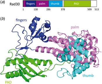
9.2 Crystal structure of the yeast XPV (Rad30) in complex with 1,2-GG cisplatin
Alt et al. (Reference Alt, Lammens, Chiocchini, Lammens, Pieck, Kuch, Hopfner and Carell2007) solved the crystal structure of XPV replicating over 1,2-GG containing DNA. This structure provided insights into the molecular mechanism that allows replication of XPV across strongly distorting DNA lesions. 1,2-GG and 1,3-GTG cisplatin adducts are formed in a typical cancer therapy with cisplatin. In the structure, XPV accommodates the full 1,2-GG adduct in its active site where it properly base pairs the 3′ G of the 1,2-GG lesion with a dCTP (Fig. 18). For the nucleotidyl transfer, the DNA rotates into an active conformation, supported by hydrogen bonding of the temple base to the dCTP. The bypass of the 3′-dG of 1,2-GG is more efficient and accurate than the bypass of the 5′-dG. In the palm domain, Asp30 and Asp155 coordinate the divalent cations in the active site and Glu156 is responsible for the catalysis. Glu39 plays a structural role too, because it maintains the integrity of the fingers domain. Arg73 coordinates the incoming dNTP for the lesion bypass step and stacks on top of the base moiety. Two magnesium ions are coordinated by the catalytically essential residues.
Crystal structure of Rad30 in complex with 1,2-GG cisplatin adduct (PDB code: 2R8 K) (Alt et al. Reference Alt, Lammens, Chiocchini, Lammens, Pieck, Kuch, Hopfner and Carell2007). Rad30 has right-hand structure containing four domains: palm (violet), thumb (cyan), finger domain (dark blue) and the additional PAD domain (green) which is unique for Y-family polymerases. The cisplatin adduct is depicted in pink, the dCTP in yellow and the two metal ions in green.

9.3 Crystal structure of the yeast XPV (Rad30) in complex with the CPD lesion
Silverstein et al. (Reference Silverstein, Johnson, Jain, Prakash, Prakash and Aggarwal2010b) determined the crystal structure of yeast Rad30 in complex with a cis–syn T–T dimer lesion. These authors argue that crystal contacts between the palm and the PAD domain of two neighboring proteins in the crystal lattice influence the binding of the protein to the DNA. The group performed a double-mutation (K140A, S144W) to eliminate these contacts, and indeed crystals were obtained with a different space group. Deeper analysis of the structure shows that the finger domain is a little more closed but the situation in the active site is almost unchanged compared with the yeast structure (Alt et al. Reference Alt, Lammens, Chiocchini, Lammens, Pieck, Kuch, Hopfner and Carell2007). Figure 19 shows the XPV structure with its different domains, the containing T–T dimer and the incoming dATP. Again the large active site accommodates the dinucleotide lesion very similar to what was already shown by Alt et al. for the cisplatin lesion. The 3′T of the dimer interacts with the incoming dATP by Watson–Crick hydrogen bonding. The 5′T of the lesion builds van der Waals contacts with Met74 and Arg73 of the finger domain. The active site residues of the palm domain (Asp30, Asp155 and Glu156) catalyze the nucleotidyl transfer reaction. By mutational analysis and biochemical assays Silverstein et al. could show that the residues Gln55, Arg73 and Met74 interact with the T-T dimer to keep the lesion in the active site.
Structure of Rad30 with a CPD lesion. The cis–syn T–T dimer is depicted in orange and the incoming dATP is shown in yellow (PDB code: 3MFI) (Silverstein et al. Reference Silverstein, Johnson, Jain, Prakash, Prakash and Aggarwal2010b). The four domains are depicted with different colors: fingers (blue), palm (violet), PAD (green) and thumb (light blue). The two Mg2+ ions in the active site are colored in red.
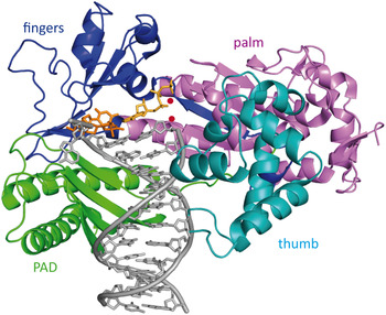
9.4 Crystal structure of the human XPV in complex with the CPD lesion
Biertumpfel et al. (Reference Biertumpfel, Zhao, Kondo, Ramon-Maiques, Gregory, Lee, Masutani, Lehmann, Hanaoka and Yang2010) reported the crystal structure of the catalytic core (residues 1–432) of human polymerase ɳ at four consecutive steps during DNA synthesis through cis–syn CPD lesion (Fig. 20b ). They could show on a molecular level how human XPV efficiently bypasses the lesion in TLS. Human XPV, similar to its yeast homolog, consists of four domains: palm, PAD (little fingers), thumb and the fingers (Fig. 20a ). The active site is situated in the palm domain and the DNA is bound between the thumb and the finger domains. Acting as a molecular splint the polymerase keeps the damaged DNA straight and rigid in its B-form conformation in contrast to the bent and unwound structures of CPD containing DNA with other repair enzymes or alone. The β-strand in the little finger is nearly parallel to the template strand and hydrogen bonding of the main chain amides to the phosphate supports this conformation. Again, the most prominent feature is the large active site of the protein already reported by Alt et al. (Reference Alt, Lammens, Chiocchini, Lammens, Pieck, Kuch, Hopfner and Carell2007), which is able to accommodate two bases of the template strand instead of one. The 3′ thymine of CPD is base paired with the incoming dATP, while the 5′ thymine is turned and moved closer to the finger domain which leads to tighter interactions than the ones observed with undamaged DNA. Furthermore, the two residues Arg61 and Glu38 that are conserved among the XPV homologs create specific hydrogen bonds with the incoming dATP and the CPD lesion. Again, the human XPV shows a more closed finger domain, which contacts the replicating base pair more intensively. Based on all these structures we can therefore assume that the finger domain is quite flexible and that the more closed structure is the conformation the protein assumes in the processive mode.
(a) Schematic representation of human XPV showing the different domains. The finger domain is depicted in purple, the palm domain in dark blue, the ThM in green and PAD domain (little fingers) in cyan. (b) Crystal structure of human XPV in complex with CPD damaged DNA (PDB code: 3MR3) (Biertumpfel et al. Reference Biertumpfel, Zhao, Kondo, Ramon-Maiques, Gregory, Lee, Masutani, Lehmann, Hanaoka and Yang2010). Same color code as in (a). The CPD lesion is shown in orange and the dAMPNPP (2′-deoxy-adenosine-5′-[(α,β)-imido]-triphosphate) is shown in yellow. The two Mg2+ ions of the active site are depicted in red.

Further crystal structures of human and yeast XPV could be resolved with different DNA damages such as 1,3-GTG cisplatin or 8-oxoG (Reissner et al. Reference Reissner, Schneider, Schorr and Carell2010; Silverstein et al. Reference Silverstein, Jain, Johnson, Prakash, Prakash and Aggarwal2010a). Schorr & Carell (Reference Schorr and Carell2010a) crystallized the S. cerevisiae XPV (Rad30) with an AAF-dG lesion and they proposed a model for lesion bypass. In vivo experiments show that Pol η indeed replicates through acetylated aromatic amine lesions such as AAF-dG (Bresson & Fuchs, Reference Bresson and Fuchs2002). In vitro studies revealed that both human and yeast XPV base pair the AAF-dG lesion correctly with dC (Bresson & Fuchs, Reference Bresson and Fuchs2002; Livneh, Reference Livneh2001; Masutani et al. Reference Masutani, Kusumoto, Iwai and Hanaoka2000; Matsuda et al. Reference Matsuda, Bebenek, Masutani, Hanaoka and Kunkel2000) and are able to catalyze the extension from the lesion, however, with reduced efficiency (Masutani et al. Reference Masutani, Kusumoto, Iwai and Hanaoka2000). In addition, XPV also incorporates a correct dCTP opposite the N 2-AAF-dG adduct (Yasui et al. Reference Yasui, Dong, Bonala, Suzuki, Ohmori, Hanaoka, Johnson, Grollman and Shibutani2004). It has also been shown that XPV is responsible for the occurrence of frameshift mutations in response to the presence of aromatic amine lesions during replication (Bresson & Fuchs, Reference Bresson and Fuchs2002; Cordonnier et al. Reference Cordonnier, Lehmann and Fuchs1999).
10. Conclusion
In this review, we presented the most recent eukaryotic structures of the XP proteins in complex with their DNA substrate. When no co-crystal structures with the DNA substrate were obtained we discussed the models of protein–DNA interaction that were proposed. All these structures led to a dramatic increase of our understanding of the role of the individual XP proteins in DNA damage repair and tolerance. The structures allow to determine binding partner regions and to elucidate on a molecular level the interaction between the proteins and their DNA substrates. Now, further studies have to be done in order to better understand the correlation between genetic defects and the role of the various XP proteins in NER and TLS. We also need further human structural information and most importantly structures of the XP proteins in functional complexes with the other involved NER proteins. This would allow deciphering of the protein–protein interactions on the DNA damage site and it may shed light on the correlation to genetic disorders. Understanding the mechanism of NER and TLS in correlation with human genetic disorders unveils the biological basis for oncogenesis and aging. Last but not least, proteomics data are needed to uncover the functional relations of the proteins involved in replication, transcription and repair.
Acknowledgements
We thank the Deutsche Forschungsgemeinschaft SFB-646, SFB-749 and the excellence cluster CIPSM for financial support. We also thank Dr. Jochen Kuper, Wolfgang Koelmel, Dr. Dorothea Matschkal, Dr. Iacovos N. Michaelides and Dr. Sabine Schneider for critical reading of the manuscript. We thank Dr. Markus Mueller for helpful advice.