Introduction
Microstrip resonators and filters [Reference Hayati, Abbasi and Shama1–Reference Benningshof, Mohebbi, Taminiau, Miao and Cory21] are applied to choose microwave signals within specific spectral limits. Planar microstrip filters have a high position in modern microwave filter designs because of their compact size, simple structure, and easy integration with other circuits [Reference Hayati, Abbasi and Shama1]. Lowpass filters (LPFs) are very popular types of microwave filters and their applications are not limited to suppress the unwanted generated harmonics [Reference Hayati, Abbasi and Shama1–Reference Rekha, Abdulla, Jasmine and Anu18]. For an LPF, a high performance compact design should contain an appropriate insertion loss, sharp transition region, and a wide rejection region. In [Reference Xu, Ma, Meng and Yeo2], a defected ground structure LPF has been introduced for obtaining an ultra-wide stopband region. This filter has many drawbacks, such as a three-dimensional structure results in design elaboration and high radiation loss. An LPF with a sharp transition region applying a semicircle patch resonator has been presented in [Reference Li, Qu and Xue3]; however, it is not compact and suffers from a low return loss. In [Reference Hayati, Shama and Abbasi4], a narrow stopband LPF, using tapered cells and bent lines has been reported. In [Reference Velidi and Sanyal5, Reference Wei, Chen and Shi6], two LPFs with a modified coupled hairpin structure with good properties have been presented in passband and stopband regions; but the harmonic rejections and the return loss parameter in the stopband are not satisfactory. In [Reference Tu and Chang7], an interdigital-structured LPF has been presented. Its insertion loss is high, and it has gradual transition region. In [Reference Zhang8], an LPF with a compact microstrip resonator cell structure has been introduced. This filter possesses disadvantages such as narrow stopband and fluctuated insertion loss in the passband region. In [Reference Wang, Cui and Zhang9], a triangular/radial-shaped LPF has been implemented. It has an ultra-wide stopband region and a high return loss in the passband region. However, its transition sharpness and insertion loss are not satisfactory. In [Reference Hayati, Khodadoost and Abbasi10], a radial-shaped LPF has been presented with wide stopband and prefect transition band, but its passband characteristics are not satisfactory. In [Reference Kolahi and Shama11], a large size multi-shaped LPF based on triangle-shaped resonators has been implemented. It has a flat group delay in its operating frequency range. In [Reference Hiedari and Shama12], a simple-shaped LPF has been fabricated. It has a very gradual transition region. In [Reference Shama, Hayati and Ekhteraei13], a meandered semi-hairpin structured LPF has been presented. It has two adjustable transmission zeros but suffers from a fluctuated passband region.
In this study, an LPF using a modified ring resonator and tapered- and rectangular-shaped suppressing cells is presented. The advantages of this design include simple shape, sharp transition region, ultra-wide stopband region, good loss performances in all of the frequency ranges, and a high overall figure of merit (OFOM). The design trend is as follows:
• Designing a conventional-stepped impedance resonator.
• Improving the prototype resonator with a new ring resonator with a circular patch and curved transmission line to obtain smaller size and better frequency performances.
• Calculating scattering parameters of the proposed resonator, to determine the effective dimensions.
• Varying effective dimensions of the designed resonator and considering their effects on the simulation results.
• Adding suitable suppressing units to the designed topology to obtain an ultra-wide stopband region.
Finally, the designed filter has been constructed on an RT/Duroid 5880 substrate with ɛr = 2.22, thickness = 0.381 mm, and loss tangent = 0.0009.
Filter design
The filter design process is presented in two sections. In the first section, a modified ring resonator with a sharp roll-off is designed, which is obtained based on an appropriate prototype lowpass resonator. In the second section, tapered- and rectangular-shaped suppressing units are designed, to achieve an ultra-wide stopband.
The modified ring resonator
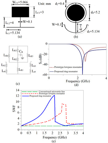
First, an appropriate prototype lowpass resonator is configured, as shown in Fig. 1(a). The physical parameters of the microstrip transmission lines (the physical lengths of the low/high impedance lines) of the prototype structure are calculated as follows [Reference Hong and Lancaster19]:


(a) Conventional lowpass resonator. (b) Ring resonator. (c) LC equivalent circuit for ring resonator. (d) Insertion loss. (e) SWF.

In the above equations, Z 0Ci and Z 0Li are the impedances of the low/high impedance transmission lines, respectively. g i is the element value of each part of the prototype lowpass resonator [Reference Hong and Lancaster19]. λ gLi and λ gCi are the guided wavelengths for high/low impedance lines, respectively. To obtain a sharper roll-off and to increase the suppression level, a ring resonator with a circular patch and curved transmission line, based on the prototype resonator is proposed, as shown in Fig. 1(b). The equivalent circuit of its lumped elements based on [Reference Hong and Lancaster19] and simulated S 21 are shown in Figs 1(c) and 1(d), respectively. According to Fig. 1(d), the roll-off rate and suppression levels of the proposed ring resonator are improved by 11 and 73%, respectively, in comparison with the prototype LPF. Another important parameter is slow wave factor (SWF) that is computed by [Reference Zhang8]:

In equation (3), d, λ 0, Δθ, and ɛeff are the microstrip physical length, the guided wavelength, the difference between a conventional microstrip phase and the newly designed resonator phase, and the effective permittivity [Reference Zhang, Ugurbil and Chen20], respectively. SWF shows the success of a resonator to reduce the size with a better frequency response in comparison with the conventional microstrip line. As shown in Fig. 1(e), in comparison with the prototype resonator, the newly designed resonator improves the SWF factor by 38% at the resonance frequency. For the LC equivalent circuit, the following simplifications are presented: Lt 1 = Lt 8 + Lb 2, Lt 2 = Lt 9 + Lb 3, L 3 = LR 4||LR 5, and LR = ((LR 3 + L 3)||LR 2) + LR 1. To find the effective dimensions, the scattering parameters are calculated.
The scattering parameters for this resonator can be calculated from ABCD parameters as follows:


where Q = jx 1 + jx 2 + jb, y = jx 2 + jb, and z = jx 1. Also, jx 1 are the impedances of the Lt 1 and Lt 2, jx 2 is impedance of the LR, and jb is the impedance of the CR. Equations (4) and (5) show the effective dimensions d 1 and d 4 of the S-parameters.
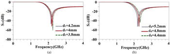
By changing the length of d 1 from 3.8 to 4.2 mm, LR 1 increases and thereby the transmission zero transports to a lower frequency that results in the sharper transition region and a decrement of attenuation at the resonance frequency, as shown in Fig. 2(a). Therefore, by choosing d 1 = 4 mm, both sharpness and good rejection are achieved. Figure 2(b) shows the insertion loss of the resonator when d 4 decreases from 5.2 to 4.4 mm. The best attenuation value of the transmission zero is obtained when d 4 is equal to 5.2 mm.
Simulated insertion losses: (a) as a function of d 1 and (b) as a function of d 4.

Suppressing unit design
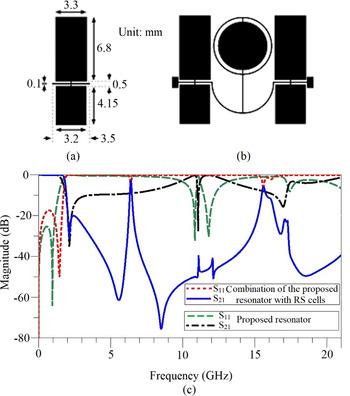
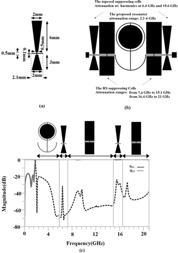
To obtain an LPF with an ultra-wide stopband, the rectangular-shaped (RS) cells are used, as suppressing units, as shown in Fig. 3(a). The combination of the proposed RS units with the ring resonator is shown in Fig. 3(b). The S-parameters of the designed resonator and the combined structure are shown in Fig. 3(c). The RS cells remove undesirable harmonics from 7.4 to 15.1 GHz and 16.4 to 21 GHz. To remove the remained harmonics at 6.4 and 15.6 GHz, tapered cells are combined into the topology as shown in Figs 4(a) and 4(b). Therefore, the width of the stopband increased significantly, as illustrated in Fig. 4(c). The RS and tapered cells are designed based on the elliptic function resonator design which is presented in [Reference Hong and Lancaster19]. Two fifth-order microstrip elliptic response LPFs with the cut-off frequencies of 5.1 and 6.4 GHz have been selected for RS and tapered cells, respectively. The element values for a five-pole (n = 5) LPF with an elliptic response and very low passband ripple (less than 0.1) are obtained from [Reference Hong and Lancaster19]. The parameters of the transmission lines as well as physical lengths of the low- and high-impedance lines are calculated by using equations (1) and (2). Finally, to increase the attenuation at resonance frequencies, they have been duplicated in horizontal.
(a) RS cells. (b) Proposed resonator with the RS cells. (c) The frequency responses.

(a) Tapered cells. (b) Designed filter. (c) Simulated results of the designed filter.

Figures 4(b) and 4(c) show the attenuation frequency range of each part of the filter. The proposed ring resonator removes harmonics from 2.1 to 6 GHz, the presented RS-suppressing cells removed undesirable harmonics from 7.4 to 15.1 GHz and 16.4 GHz to 21 GHz. The presented tapered-suppressing cells removed harmonics at 6.4 and 15.6 GHz, as shown in Figs 4(b) and 4(c).
Design results
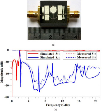
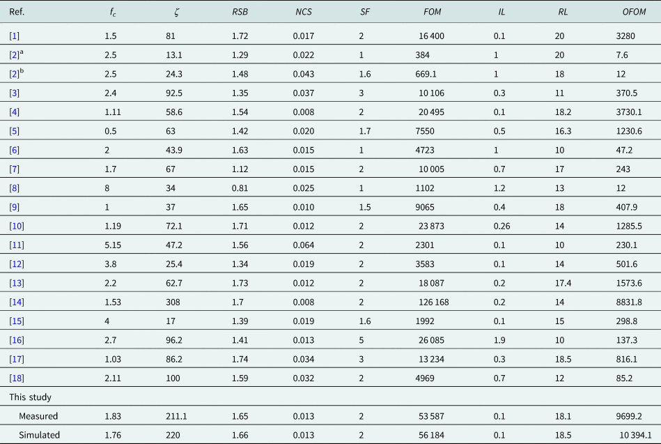
A photograph of the fabricated LPF and practical results are illustrated in Figs 5(a) and 5(b), respectively. According to Fig. 5(b), the LPF has a transition region equal to 0.27 GHz, which is from 1.83 (at −3 dB) to 2.1 GHz (at −60 dB). A stopband region has been concluded from 2 to 21 GHz (with the corresponding attenuation level of at least 20 dB). The measured insertion loss is better than 0.1 dB (equal to a return loss of 18.1 dB) in the passband region. The calculated size of the circuit is 200 mm2 (equal to $0.013\lambda _g^2$ mm2). The newly designed LPF is compared with some recently published samples in Table 1. In this table, fc, IL, and RL are −3 dB cut-off point in GHz, insertion and return losses (in the passband region), respectively. ζ, RSB, NCS, SF, and FOM are defined parameters [Reference Hayati, Abbasi and Shama1] of sharpness rate, relative stopband bandwidth, normalized circuit size, suppression factor, and figure of merit, respectively.
(a) Photograph of the filter. (b) Final results.

Compression table

RSB, relative stopband; NCS, normalized circuit size; SF, suppression factor; FOM, figure of merit; IL, insertion loss; RL, return loss; OFOM, overall figure of merit.
The Reference [Reference Xu, Ma, Meng and Yeo2] has presented two works, they are shown by a and b.
The FOM does not show a global performance for an LPF. The important parameters of RL and IL are not included in the FOM equation. Therefore, a new parameter for OFOM is presented below [Reference Hayati, Khodadoost and Abbasi10]:

Table 1 shows that the designed LPF has the highest OFOM in comparison with the references. The simulated and measured results are presented in Table 1 to have a quantitative comparison between them. As can be seen, the measured results have declined somewhat, because of the SMA soldering and fabrication tolerance.
Conclusion
In this paper, using a ring resonator and a pair of suppression units, an ultra-wide rejection region LPF has been designed. The proposed filter has also good loss characteristics in all of the operational bands. The filter has been constructed and tested. The OFOM is so significant for this LPF and makes it a high-performance candidate to be applied in microwave circuits and systems.
 Mohsen Hayati obtained B.E. in electronics and communication engineering from Nagarjuna University, Andhra Pradesh, India, in 1985, and M.E. and Ph.D. in electronics engineering from Delhi University, Delhi, India, in 1987 and 1992, respectively. He joined the Electrical Engineering Department, Razi University, Kermanshah, Iran, as an assistant professor in 1993. Currently, he is a professor at the Electrical Engineering Department, Faculty of Engineering, Razi University. He has published more than 250 papers in international, domestic journals, and conferences. His current research interests include microwave and millimeter wave devices and circuits, power amplifiers, low-noise amplifier design, analog cmos circuit, application of computational intelligence, artificial neural networks, fuzzy systems, neuro-fuzzy systems, electronic circuit synthesis, modeling and simulations.
 Sajjad Mohanad Mustafa obtained his graduate degree in electrical engineering from Kufa University, Najaf, Iraq, in 2012, and his M.Sc. in electrical engineering/electronics from Razi University, Kermanshah, Iran, in 2016, where he is currently a PhD student at the Department of Electrical Engineering, Razi University, Kermanshah, Iran, under the supervision of professor Mohsen Hayati and Associate Professor Gholamreza Karimi.
 Farzin Shama obtained B.E., M.E., and Ph.D. in electronics from Razi University, Kermanshah, Iran in 2009, 2012, and 2016, respectively. Now, he is an assistant professor in Kermanshah Branch, Islamic Azad University, Kermanshah, Iran. He was the head of electrical engineering department between 2018 and 2019. His research interests include artificial intelligence, complex circuits and systems solutions, analog circuits and design, microwave engineering, passive and active circuits design and fabrication, photovoltaic cell design, and neuron implementation. He was proud to achieve an award of superior researcher in the engineering faculty of Razi University in 2011 and 2012. Also, he has been selected as the top student of Iran for his Ph.D. in 2015. He has published more than 80 papers in international, domestic journals and conferences. He was also awarded superior researcher in the engineering faculty of Kermanshah Branch, Islamic Azad University in 2018.
 Hamed Abbasi was born in Kermanshah, Iran in 1987. He obtained B.Sc. in electronics engineering from the Islamic Azad University of Kermanshah, Iran in 2008 and obtained M.E. and Ph.D. in electrical engineering from the Razi University, Kermanshah, Iran in 2012 and October 2018, respectively. He is currently an assistant professor at Islamic Azad University of Kermanshah, Iran. His research interests include design and analysis of the microwave circuits, power amplifiers, low-noise amplifier (LNA), microstrip filters, couplers, and antennas.