I. INTRODUCTION
Recently, there have been extensive studies in the development and characterization of nanolayered metallic multilayer systems.Reference Anderson and Li1–Reference Budiman, Li, Wei, Baldwin, Xiong, Luo, Trugman, Jia, Tamura, Kunz, Chen and Misra16 The metallic multilayers are known to exhibit ultra high strengths due to the effective constraint of the dislocation movements, and the strength has been shown to depend on the bilayer spacings.Reference Huang and Spaepen8–Reference Misra, Hirth and Hoagland15 Therefore, the metallic multilayer systems have a key advantage in being able to control the strength by controlling the bilayer spacings: the smaller the layer spacing, the higher the strength. The controllable, ultra high strength of the metallic multilayers have potential usage in the automobile and aerospace applications, where high strength-to-weight ratio is desired.
The deformation mechanism that is responsible for the high strength of the multilayers is dependent on the bilayer spacings. For the bilayer spacings in the range of micrometers, the conventional hardening mechanism from dislocation pile-up at the interfaces occurs. In this regime, the Hall-Petch effect has been identified as the strengthening mechanism, where σ ∝ h 1/2 (σ is the stress and h is the layer thickness).Reference Misra, Verdier, Lu, Kung, Mitchell, Nastasi and Embury6–Reference Misra, Hirth, Hoagland, Embury and Kung9, Reference Misra, Hirth and Hoagland15–Reference Friedman and Chrzan18 However, as the bilayer spacing is reduced to a range of tens of nanometers, the deformation mechanism changes to a single dislocation bowing or a confined slip of a single dislocation.Reference Pande, Masumura and Armstrong19–Reference Nix23 In this regime, the stress needed to drive the confined dislocation forward is inversely proportional to the layer thickness h (σ ∝ 1/h).
In respect of coherent interfaces, the increase in strength with reduction in bilayer spacing reaches a plateau at ∼5 nm, below which the strength is determined by the interfacial resistance for direct transmission of a single dislocation.Reference Hoagland, Kurtz and Henager24 However, for the incoherent multilayer systems such as the face-centered cubic (fcc)–body-centered cubic (bcc) multilayer systems, the simulations study by Hoagland et al.Reference Hoagland, Mitchell, Hirth and Kung21, Reference Hoagland, Hirth and Misra25 indicate that these incoherent interfaces present a stronger barrier for slip transmission as compared with the coherent interfaces. Stronger resistance for slip transmission across the incoherent interfaces has been suggested to be due to a geometric discontinuity of slip systems across the fcc–bcc incoherent interface as well as the dislocation core spreading at “weak interfaces.”Reference Wang, Hoagland, Hirth and Misra22 A “weak interface” refers to an incoherent multilayer interface with low shear resistance that can be readily sheared by a gliding dislocation, and the sheared interface then would generate an attractive force on other glide dislocations, which would spontaneously enter the interface to result in dislocation core spreading. Therefore, transmission of dislocations across the interface would be hindered due to this core spreading process. The proposed spontaneous attraction of lattice dislocations and the core spreading at the interface would lead to “self-healing” capability. Therefore, the incoherent multilayers are well suited for nuclear reactor storage material applications due to their ability to clear out the dislocations from the plastically deformed regions.
In evaluating the high strength of the multilayered systems, the Berkovich tip nanoindentation has been commonly used to determine the hardness of the nanolayered composite,Reference Han, Phillips and Nix12–Reference Misra, Hirth and Hoagland15 and the Tabor relation can then be used to estimate the yield strength of the material from the hardness measurements.Reference Han, Phillips and Nix12, Reference Misra, Hirth and Hoagland15 However, use of the Berkovich tip hardness testing has complications arising from the substrate effectReference Han, Saha and Nix26–Reference Saha and Nix28 in the case of multilayers deposited on top of a substrate and also from the geometrically induced dislocations introduced by the Berkovich tip.Reference Nix and Gao29–Reference Huang, Xue, Gao, Nix and Xia32 In addition, the hardness measurements do not enable direct measurements of the stress-strain behavior from which the yield strength and strain hardening characteristics can be analyzed. To avoid these complications, the microcompression technique developed by Uchic et al.Reference Uchic, Dimiduk, Florando and Nix33 has been applied to the multilayer systems to directly evaluate the yield strength from stress versus strain plots and also to study the strain hardening behavior of the multilayers.Reference Mara, Bhattacharyya, Hirth, Dickerson and Misra4, Reference Mara, Bhattacharyya, Dickerson, Hoagland and Misra5, Reference Han, Phillips and Nix12
In this study, the microcompression testing technique was used to study the strength and plasticity of Al-Nb incoherent multilayer systems, and the results were compared with the work of Mara et al. on Cu-Nb multilayer microcompression study.Reference Mara, Bhattacharyya, Hirth, Dickerson and Misra4, Reference Mara, Bhattacharyya, Dickerson, Hoagland and Misra5 Study of Al-Nb in comparison with that of Cu-Nb will enable us to gain insight into the proposed theory by Wang et al.Reference Wang and Misra10, Reference Wang, Hoagland, Hirth and Misra22, Reference Wang, Hoagland, Hirth and Misra34 on the strengthening effect arising from difference in interfacial strength of the multilayers.
II. EXPERIMENTAL PROCEDURES
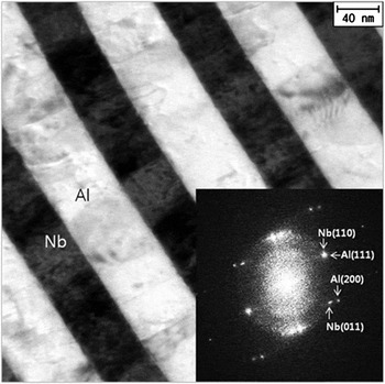
Al-Nb multilayers were deposited onto (001) Si substrate at room temperature using DC magnetron sputtering. The sputtering deposition parameters were ∼0.59 nm/s deposition rate with Ar pressure of 6 mTorr at a power of 300 W for Al and 0.52 nm/s, 6 mTorr, 350 W for Nb. Two samples of 5 nm Al/5 nm Nb and 50 nm Al/50 nm Nb were synthesized, and the total thickness of the multilayers is 15 μm in both cases. The Al-Nb multilayer in Fig. 1 has {111} fcc Al on {110} bcc Nb out-of-plane orientation, known as the Kurdjumov-Sachs orientation relationship. The multilayers are polycrystalline, but they have a strong {111} Al//{110} Nb texture. Transmission electron microscopy (TEM) analysis of the multilayers was performed using the FEI Tecnai F20 TEM (Eindhoven, Netherlands) at 300 kV to characterize the interface before and after deformation.
Bright-field TEM (BF TEM) for the Al-Nb multilayers with 50 nm Al/50 nm Nb layer spacing. The selected area diffraction in the inset confirms the {111} Al//{110} Nb Kurdjumov-Sachs orientation relationship.

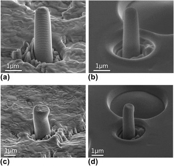
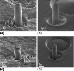
The Nova 200 dual-beam focused ion beam (FIB) in National Nanofab Center at KAIST was utilized to fabricate the micropillars. Special care was taken to minimize the ion beam exposure of the top surface of pillar structure to minimize the defect introduction from the FIB process. A pedestal of 17 μm in outer diameter and 8 μm in inner diameter was first made with coarse current, and the pedestal was reduced down to the final pillar dimension using finer ion beam currents. The final pillar dimension used for this study is kept the same at 1 μm in diameter and 3 μm in length for both 5 nm Al/5 nm Nb and 50 nm Al/50 nm Nb layer spacing specimens to study the effect of the bilayer thicknesses on the strength of the materials excluding any external sample dimension size effects. The 3:1 length-to-diameter ratio is used to avoid buckling of the sample during compression. Scanning electron microscopy (SEM) micrographs of representative pillars before deformation are shown in Figs. 2(a) and 2(b).
SEM micrographs of pillars. (a) 50 nm Al/50 nm Nb layer thickness and (b) 5 nm Al/5 nm Nb layer thickness micropillar before compression. (c) 50 nm Al/50 nm Nb layer thickness and (d) 5 nm Al/5 nm Nb layer thickness micropillar after compression.

The fabricated micropillars were tested using the Hysitron TI-750 Ubi nanoindenter (Minneapolis, MN) with a Performech controller, and a flat ended cube corner tip with inscribed circle of 10 μm in diameter was used for compression of the micropillars. All pillars were compressed at a nominal constant displacement rate of  , which translates to nominal engineering strain rate of
 for a micropillar with a length of 3 μm. The SEM micrograph of each micropillar was taken before and after deformation to ensure successful axial compression of each micropillar. Representative micrographs of deformed micropillar from 50 nm Al/50 nm Nb and 5 nm/5 nm layer spacings are showed in Figs. 2(c) and 2(d), respectively.
III. RESULTS AND DISCUSSION
The synthesized micropillars from both 5 nm/5 nm and 50 nm/50 nm Al/Nb layer thicknesses were tested in compression, and the resulting load versus displacement data were analyzed using a constant volume, homogeneous deformation assumption model. This model has been suggested in previous publications,Reference Han, Phillips and Nix12, Reference Han, Bozorg-Grayeli, Groves and Nix35, Reference Han, Xie and Cui36 but the procedure will be reviewed here to aid readers’ understanding. First step in the analysis requires subtraction of the Sneddon compliance that arises due to the bottom cross sectional area of the micropillar punching into the underlying material. This Sneddon compliance is subtracted from the total displacement to calculate the displacement that corresponds to the pure deformation of the nanopillar only,


Here, the E refers to the modulus of the multilayer as determined by their volume fractions of Al and Nb (E = V AlE Al + V NbE Nb), and ν is the multilayer Poisson’s ratio also determined based on their volume fractions (ν = V AlνAl + V NbνNb). Note that the total thickness of the multilayers is larger than the length of pillar, and this is the reason why the multilayer elastic properties are being used for the Sneddon substrate properties. Since both of 5 nm Al/5 nm Nb and 50 nm Al/50 nm Nb layer spacings have 1:1 Al to Nb volume ratio, their composite modulus and Poisson’s ratio would be the same. The modulus and Poisson’s ratio of Al is 70 GPa and 0.35, and that of Nb is 105 GPa and 0.4, and the composite modulus and Poisson’s ratio for both 5 nm Al/5 nm Nb and 50 nm Al/50 nm Nb layer spacings specimens are 87.5 GPa and 0.375, respectively.
The corrected u pillar for pure nanopillar displacement is then used to evaluate the stress versus strain behavior. Assuming that the volume of the pillar is conserved and that the pillar is deforming uniformly, then A 0L 0 = ApLp or Ap = A 0L 0/Lp, where A 0, Ap are the initial top and the instantaneous top cross sectional areas during deformation, and L 0, Lp are the initial and the plastically deformed lengths of the pillar. The Lp can then be determined by the remainder of the initial length of the pillar and the plastic displacements, Lp = L 0 – u plastic = L 0 – (u pillar – u elastic) where the elastic displacement is given by

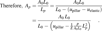
which can be solved for Lp to obtain, 
Finally, Lp is inserted to calculate, Ap = A 0L 0/Lp which can now be used to calculate the true stress and true strain. The true stress and the true strain are given by

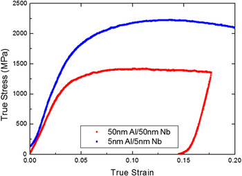
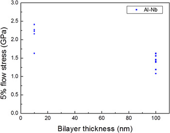
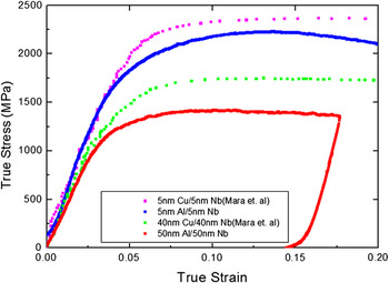
The true stress versus true strain behavior calculated using the above mentioned constant volume, homogeneous deformation assumption model is presented in Fig. 3. Representative results of Al-Nb micropillars synthesized from both 5 nm Al/5 nm Nb and 50 nm Al/50 nm Nb layer thicknesses are plotted together for comparison. As shown in Fig. 3, the 5 nm Al/5 nm Nb spacing micropillars clearly showed higher yield strength and flow stresses as compared with the 50 nm Al/50 nm Nb layer spacing micropillars. The average flow stresses at 5% plastic strain from 10 individual microcompression data for 50 nm Al/50 nm Nb layer spacing specimen was 1.4 GPa with standard deviation of 0.17 GPa, where as the average flow stress at 5% plastic strain from five microcompression data for the 5 nm Al/5 nm Nb layer spacing specimen was 2.1 GPa with standard deviation of 0.27 GPa. This significant increase in the strength of the micropillar with the reduction in the bilayer spacing is in agreement with the microcompression results of Han et al.Reference Han, Phillips and Nix12 who showed similar strengthening for the case of Al-Al3Sc multilayers. For our Al-Nb multilayers with 5 nm Al/5 nm Nb and 50 nm Al/50 nm Nb layer spacings, we expect that the strengthening mechanism to be due to the increased resistance to glide the dislocation within the confined layer as the layer spacing is decreased. The increase in the flow stresses with decrease in the bilayer spacing can also be clearly seen in a plot of 5% flow stresses versus bilayer thickness shown in Fig. 4. The 5 nm Al/5 nm Nb sample is noted as bilayer spacing of 10 nm, and the 50 nm Al/50 nm Nb sample is noted as bilayer spacing of 100 nm.
The stress versus strain plot for the micropillars synthesized from the Al-Nb multilayers with 5 nm Al/5 nm Nb and 50 nm Al/50 nm Nb layer thicknesses.

The 5% flow stress versus bilayer thickness plot showing that the Al-Nb specimen strength is increased with decreased bilayer spacing.

Our flow stress measurements from the 5 nm Al/5 nm Nb specimen were compared with the estimate of yield strength based on the Berkovich tip nanoindentation hardness reported by Fu et al.Reference Fu, Li, Misra, Hoagland, Wang and Zhang37 Fu et al.Reference Tabor38 has shown that the hardness at 150 nm indentation depth for the 5 nm Al/5 nm Nb specimen is 4.8 GPa, which translates to  by using the Tabor relation. Our 5% flow stress measurement for the 5 nm Al/5 nm Nb specimen is 2.1 GPa, and this is comparable yet higher than the estimated yield strength from the hardness reported by Fu et al. The 5% flow stress is expected to be higher since our multilayers are showing strain hardening behavior during the initial stages of plastic deformation.
Our results from the Al-Nb compression testing were then compared with the results for Cu-Nb by Mara et al.Reference Mara, Bhattacharyya, Hirth, Dickerson and Misra4, Reference Mara, Bhattacharyya, Dickerson, Hoagland and Misra5 to gain insight into the effect of the interfacial shear strength on the overall strength of the multilayer. As shown in Fig. 5, the flow stresses from Al-Nb multilayers with 5 nm Al/5 nm Nb layer spacing are lower than those for Cu-Nb multilayers with the same layer spacing. The same trend also holds for the flow stress comparison between the 50 nm Al/nm Nb multilayer to those of the 40 nm Cu/40 nm Nb multilayers. However, a portion of the observed lower flow stresses for the 50 nm Al/50 nm Nb multilayers could be due to the fact that we are comparing the 50 nm Al/50 nm Nb layer thickness result to that of the smaller layer spacing in 40 nm Cu/40 nm Nb multilayers.
The stress versus strain plot of Al-Nb pillars with 5 nm Al/5 nm Nb and 50 nm Al/50 nm Nb thickness and Cu-Nb with 5 nm Cu/5 nm Nb and 40 nm Cu/40 nm Nb layer thickness.

The general trend of the lower flow stresses being reported for Al-Nb as compared with that of Cu-Nb could be attributed to the Cu-Nb interface possibly having a lower interfacial shear strength in relation to that of the Al-Nb.Reference Fu, Li, Misra, Hoagland, Wang and Zhang37 As explained previously, an incoherent multilayer with low shear resistance can be readily sheared by a gliding dislocation, and the sheared interface would then attract other glide dislocations, which would spontaneously enter the interface to result in dislocation core spreading. If we presume that the Al-Nb has a “stronger interface” as compared with the Cu-Nb, then the initial shear of interface would be more difficult and the dislocation core spreading at the interface would be less as compared with the case of Cu-Nb. In such a case, then the Al-Nb interface would have less benefit of the dislocation core spreading that restricts dislocation transmission across the interface and would, therefore, lead to lower flow stresses.
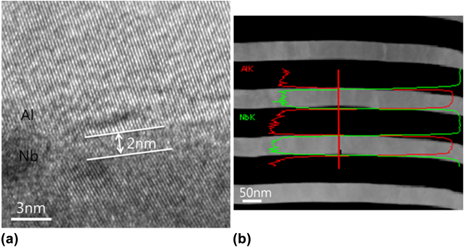
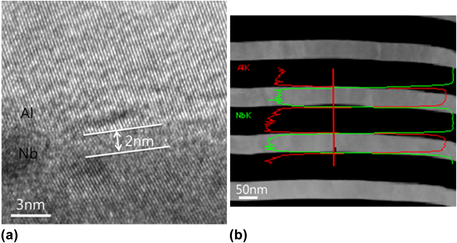
To provide experimental evidence for the Al-Nb multilayers having a “stronger interface” that is more shear resistance as compared with the Cu-Nb multilayers, we examined the degree of atomic intermixing at the Al-Nb interface. The multilayers with a higher degree of intermixing would result in a “stronger interface” with higher shear resistance, and the dislocation core spreading will be less pronounced. The intermixed layer in the Al-Nb multilayers can be seen in the high-resolution transmission electron microscopy (HRTEM) micrograph as shown in Fig. 6(a). Intermixing of Al with Nb was observed with a thickness of 2.0 nm, which is significantly larger than the previously reported intermixing in Cu-Nb that indicated essentially no intermixing at the Cu-Nb interface.Reference Yu-Zhang, Embury, Han and Misra39 The increased amount of intermixing in the Al-Nb interface is in agreement with the fact that the Al-Nb has a negative heat of mixing whereas the Cu-Nb has a positive heat of mixing. We have also performed energy dispersive x-ray spectroscopy (EDS) profile scan across the interface that reported similar intermixing thickness of 3.5 nm. The mismatch between our HRTEM measurement and EDS measurement is as expected, considering the fact that the EDS nanoprobe itself has dimension in the order of ∼1 nm. Therefore, our TEM characterization of Al-Nb shows a higher degree of intermixing than the previously reported Cu-Nb, and this would translate to the “stronger interface” for shear resistance.
(a) HRTEM image of Al-Nb interface showing that the thickness of the intermixing is 2.0 nm. (b) Scanning transmission electron microscopy image of Al-Nb layers and the EDS line profile across the interface showing that the average distance of intermixing is 3.5 nm for the 50 nm Al/50 nm Nb specimen.
Another factor that contributes to generally lower flow stresses in Al-Nb multilayers as compared with the Cu-Nb multilayers is that the Al-Nb multilayers have a close match in the interplanar spacings of Al (111) and Nb (110) with  and
 . Therefore, the dislocations in the Al-Nb multilayers will see less distortion as the dislocations propagates from one layer to the other that would result in lower flow stresses. The Cu-Nb multilayers, however, have a larger mismatch in interplanar spacing with
 and
 that would lead to increased difficulty in dislocation propagation and increased flow stresses.
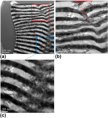
One of the micropillars from the 50 nm Al/50 nm Nb layer spacing specimen after being tested in compression was also examined with TEM to gain insight into the dislocation activity during deformation. Figure 7(a) is the low magnification view of the deformed micropillar, and it is apparent that there is a macroshear of the multilayers at 60°–70° to the multilayer interfaces. Figures 7(b) and 7(c) show the high magnification views of the sheared layers at the top and middle sections of the micropillar. As indicated previously, Al-Nb multilayers are expected to have limited dislocation absorption at the interface via core spreading, which will cause easier dislocation transmissions across the interface. The sheared interface will now be less effective in dislocation transmissions that would lead to a localized shear deformation or a macroshear event as shown in Figs. 7(b) and 7(c). The active slip system in Al is {111} and in Nb is {110} and these are at 70.5º and 60º angles with respect to the interface, respectively, and the experimentally observed angle between the macroshear plane and the interface in Fig. 7(b) appears to be in agreement. The localized shear along the 60º–70.5º angle slip plane would lead to overall bending of the micropillar as shown in Figs. 2(c) and 7(a). This type of overall bending of the micropillars were often observed in the SEM micrographs of the deformed micropillars, and the suggested macroshear may be an inherent deformation mechanism in these multilayers with incoherent interfaces that have limited ability to absorb dislocations during deformation.
(a) Cross-sectional BF TEM image of deformed pillar at low magnification, higher magnification view of the regions of macroshear that are highlighted in (b) red box and (c) blue box for the 50 nm Al/50 nm Nb specimen.

In the work by Li et al.Reference Li, Wang, Huang, Misra and Zhang40 the dislocation interaction at the Al-Nb interface during in situ TEM nanoindentation was studied. Li et al. reported a preferential storage of dislocations at the interface instead of the dislocation remaining within the lattice. However, it should be noted that the work by Li et al.Reference Li, Wang, Huang, Misra and Zhang40 is for a nanoindentation experiment that imposes an average strain of 7% for the case of a Berkovich tip, and our microcompression work imposes ∼20% total strain. Therefore, during the earlier stages of deformation, the preferential storage of dislocations at the interfaces may occur, but the mechanism may change to the suggested macroshear when a larger amount of plastic deformation is imposed onto the multilayers.
IV. CONCLUSION
In this study, microcompression of Al-Nb multilayer system with bilayer spacings of 5 nm and 50 nm were performed to examine the effect of different bilayer spacings on the deformation behavior of this incoherent multilayer system. The strength of the Al-Nb multilayers was shown to decrease with reduction in bilayer thickness. The average flow stress at 5% plastic strain is reported to be 1.4 GPa for 50 nm Al/50 nm Nb layer spacing and 2.1 GPa for 5 nm Al/5 nm Nb layer spacing. Our microcompression results from Al-Nb multilayers were then compared with the published results from Mara et al. for the Cu-Nb multilayers with 5 nm Cu/5 nm Nb and 40 nm Cl/40 nm Nb layer thicknesses to gain insight into the effect of different interfacial strength on the observed strength and plasticity of incoherent multilayer systems. Our results showed that the Al-Nb multilayers have lower flow stresses as compared with the Cu-Nb, and this was attributed to the potential difference in the interface strengths. The Al-Nb has a negative heat of mixing that would lead to higher degree of intermixing and thus a “stronger interface” in shear. As a result, the Al-Nb multilayers are expected to have lower barrier to slip transmission and therefore lower flow stresses as compared with the Cu-Nb multilayers, which would have a “weaker interface” in shear that would act as a strong trap for the glide dislocations via core spreading at the interface.
ACKNOWLEDGMENTS
The research at KAIST was supported by National Research Foundation of Korea under the Contract Nos. 4.0007357, N01110283, and the KINC grant at KAIST under the Contract No. N10110033. LANL authors acknowledge support from DOE, Office of Science, Office of Basic Energy Sciences, Division of Materials Science and Engineering. A.S.B. is supported by the Director, Los Alamos National Laboratory (LANL), under the Director’s Postdoctoral Research Fellowship program (LDRD/X93V).