Introduction
Testing thermal-barrier coating (TBC) systems and evaluating their performance in service presents major challenges. First and foremost, the conditions under which they operate are often extremely harsh, combining high temperatures, steep temperature gradients, fast temperature transients, high pressures, and additional mechanical loading, as well as oxidative and corrosive environments. These are difficult to reproduce in the laboratory. The coating system also changes with time and temperature as interdiffusion occurs, microstructures evolve, and the properties of the constituent multilayer materials change. For instance, the oxide topcoat sinters,Reference Zhu and Miller1, Reference Vaßen, Czech, Malléner, Stamm and Stöver12 increasing both its thermal conductivity and elastic modulus, but the rate of sintering depends on its purity. Furthermore, the properties that need to be evaluated are rarely those of the constituent bulk materials themselves. For instance, while the intrinsic fracture toughness of the ceramic topcoat—typically made of 7 wt% yttria-stabilized zirconia (7YSZ)—is important, it is the toughness that a delamination crack experiences as it extends in or near the interface with the thermally grown oxide (TGO) that directly influences the lifetime under thermal cycling conditions. As coatings become prime-reliant, meaning that they can be implemented into the design of the engine with reliable performance criteria, it is also essential to develop sensors and nondestructive evaluation methods to monitor TBC temperatures, the extent of sub-critical delamination in service, as well as identifying manufacturing flaws, while also creating an artificial intelligence supervisory system that can be implemented in the field to provide feedback to the manufacturing and design sectors for product improvement. Several sensor approaches are being explored, including infrared imaging, Raman spectroscopy, thermography, impedance spectroscopy, acoustic emission, and luminescence sensing.Reference Yu and Bennett2–Reference Bison, Marinetti, Grinzato, Vavilov, Cernuschi and Robba7
Mechanical properties
One of the fundamental problems in discussing and evaluating the mechanical properties of coatings is establishing what the appropriate value of a particular property should be and at what microstructural scale it should be determined. This is especially true of the oxide topcoat since considerable variability and uncertainty arise from the porous nature of the coating as well as its anisotropy and microstructural evolution at elevated temperatures. For simple properties, such as the overall thermal expansion mismatch stresses on thermal cycling and the available elastic strain energy release rate, the macroscopic biaxial Young’s modulus, such as determined by a macroscopic mechanical test, is generally adequate, recognizing that it can be expected to be different under tension than compression. In contrast, the local modulus obtained by nanoindentation, for instance, pertains to the modulus of the intrinsic material and local stiffness but not to the generation of average thermal cycling induced stresses. The same issue pertains to distinguishing macroscopic and local thermal conductivity. For this reason, there is intense interest in using local information, such as that obtained from nanoindentation, together with tomographic images to predict overall properties using object-oriented finite element (OOF) methods, such as the OOF tool available on the National Institute of Standards and Technology web page.8
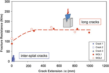
While this is a very promising methodology, it is less suited to understanding or predicting crack growth, since it does not depend on just the average mechanical properties. For small crack lengths, crack growth rates are mainly controlled by intrinsic fracture toughness. For YSZ, this property is unusually high for an oxide and has recently been attributed to ferroelastic domain switching.Reference Mercer, Williams, Clarke and Evans9 Understanding the toughening processes in YSZ also provides guidance for the selection and design of new TBC materials with enhanced toughness levels. One of the surprising results of recent measurements has been that fracture resistance for long cracks in TBCs, for instance those associated with coating delamination, is at least four times higher than the intrinsic toughness, as can be seen in Figure 1 comparing the maximum value for short (inter-splat) cracks and the mean for long cracks. While it has always been recognized that microstructure must play a role in the fracture of TBCs, the magnitude of the toughening enhancement, on the order of 150 N m–1,Reference Malzbender, Wakui, Wessel and Steinbrech10 and extent of the R-curve (rising toughness with increasing crack extension) is considerably larger than anticipated. The origin of the R-curve in plasma-sprayed and electron-beam physical vapor deposited (EBPVD) TBCs is now known to differ in detail but is essentially due to local crack deflections resulting in a tortuous crack path forming microstructural heterogeneities whose relative motion during crack propagation results in friction. Details on crack path and toughening mechanisms are discussed in References 10 and 11.
Crack resistance of inter-splat cracks (formed between individual deposition splats during cooling) and R-curve from extension of long delamination cracks in wedge opening loading (WOL).

Thermal gradient testing
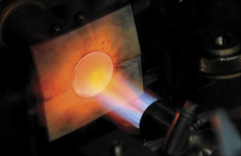
Testing coatings under extreme temperature gradients and heat flux conditions approximating actual engine operation poses special challenges. One approach has been to use a high-power CO2 laser rig,Reference Zhu and Miller13 such as implemented at the NASA Glenn Research Center,Reference Zhu and Miller14 and the other is to use a flame rig configuration in which heat is applied to one side of a coating by an oxygen/hydrocarbon gas flame.Reference Traeger, Vaßen, Rauwald and Stöver15 In both cases, the samples are cooled from the back side with a high-pressure compressed air jet. While these configurations are less suitable for testing complex shaped blades and vanes, these new testing platforms can be used to evaluate fundamental coating properties such as rates of sintering, thermal cycle lifetimes, thermal conductivities, and to monitor damage evolution under high-flux conditions of planar TBC systems, such as coated superalloy buttons. These configurations also allow for the introduction of particulates (sand, ash), water, and salt during testing, as shown in Figure 2Reference Steinke, Sebold, Mack, Vaßen and Stöver16 to evaluate the degradation they may cause. At high surface temperature, or with particulate addition, this type of testing typically results in subsequent chipping of surface layers due to the thermal gradient present (see the article by Levi et al. in this issue). Actual coating failure modes identified from engine testing or from service operation are usually complex, largely depending on excursions from standard engine operating conditions, and processed coating composition, architecture, and microstructures. Nevertheless, once a particular failure mode has been identified, the tests can be used to evaluate coatings under similar conditions.
Photograph of the Jülich gas burner rig heating a disk-shaped thermal-barrier coating sample with back-side compressed air cooling. In the central part of the flame, a solution of calcium-magnesium alumino-silicates is injected to spray onto the hot surface.

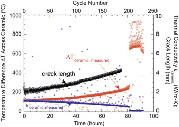
Since the initial development of the steady-state CO2 laser (wavelength 10.6 μm) test facility at NASA Glenn Research Center and its application to measuring the sintering of coatings and thermal conductivity for instance,Reference Zhu and Miller17–Reference Zhu and Miller19 its capabilities have subsequently been extended. Among the most recent is evaluating interface crack propagation under extreme heat flux and cyclic loading conditions,Reference Zhu, Choi and Miller20 such as might occur during repeated aircraft takeoff. Figure 3 shows the test results at this facility of a 127-μm-thick, precracked TBC specimen, with the crack introduced at the TBC/bond-coat interface. The initial ceramic surface temperature was set at approximately 1287°C and 20-min heating/cooling cycles with 60–100 W cm–2 heat flux were applied. The coating surface temperature increased continuously as the crack propagated, whereas the metal backside temperature remained relatively constant. The apparent coating thermal conductivity, calculated from the known laser heat flux, decreased as the delamination crack grew until the test was interrupted by spallation of the coating after about 200 cycles. The crack propagation process was also monitored independently by a high sensitivity video camera for calibrating the crack propagation with cycles. From these data, the crack propagation rate (da/dN) and the laser thermal transient stress associated stress intensity factor amplitude (ΔK) (the crack propagation driving force on the coating) for the plasma sprayed 7–8YSZ were also determined.Reference Zhu, Choi and Miller20 The results show slower thermal fatigue crack propagation rates compared to monolithic ceramics, indicative of additional R-curve toughening effects due to the roughness and plasticity at or near the ceramic/metal interface.
Laser heat flux thermal gradient cyclic test results of a 127-μm-thick, precracked thermal-barrier coating specimen subject to 20 min heating and 4 min cooling thermal cycling. The initial circular crack was 2 mm in diameter. The effective thermal conductivity clearly correlates with the crack propagation until the coating spalled after 200 cycles.

Thermomechanical fatigue
As with other high-temperature materials, including superalloys, thermomechanical fatigue (TMF) can adversely influence coating durability.Reference Baufeld, Tzimas, Mullejans, Peteves, Bressers and Stamm21–Reference Wright24 The origin of TMF is creep and plastic deformation in each of the component layers in the TBC system driven by the coefficient of thermal expansion (CTE) mismatch, especially the CTE mismatch between the bond coat, the superalloy, and the topcoat under thermal gradient conditions, as well as mechanical loads, such as centrifugal force. Testing under TMF conditions is essential, but the wide variety of possible in-phase mechanical and temperature loadings and out-of-phase loading conditions as well as realistic thermal gradient conditions makes this a demanding materials engineering task that is only now being addressed. Even so, there have been surprises. One is that contrary to initial expectation, compressive deformation is the major form of damage in strain-controlled in-phase and stress-controlled out-of-phase modes.Reference Kitazawa25 Another is that cracks can nucleate in the bond coat at high-temperatures and propagate into the superalloy.
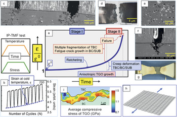
Figure 4 illustrates characteristic damage accumulation behavior in EBPVD TBC systems in an in-phase stress-controlled TMF test mode.Reference Kitazawa, Tanaka, Kagawa and Liu26, Reference Tanaka, Mercer, Kagawa and Evans27 The temperature of the substrate is kept at a constant 1000°C, while the TBC surface is heated to 1150°C and cooled again over 960s cycles. An uniaxial tensile load of 1.8 kN (60 MPa) is applied to the specimen while the TBC surface is heated. Evolution of strain with time and numbers of loading cycles under in-phase TMF test conditions are consistent with the creep behavior of superalloys (Figure 4a). Ratcheting behavior,Reference Tanaka, Mercer, Kagawa and Evans27 where the materials are left permanently deformed after each cycle, is superimposed on the creep behavior, as illustrated in Figure 4b. This behavior is consistent with most of the applied load being supported by the superalloy substrate. However, the creep behavior of the EBPVD TBC layer is interesting: at 1150°C, the layer can deform up to about 8% tensile strain without evidence of visible cracking.Reference Tanaka, Liu, Kim and Kagawa28 With increasing tensile creep strain, cracking of the TBC layer initiates, and, ultimately, multiple fragmentation occurs, as seen in Figure 4c–d. It is found that the cracks in the TBC layer do not propagate through the entire thickness, and the crack spacing of the TBC layer (Figure 4d) is much smaller than that predicted using continuum mechanics.Reference Tanaka, Mercer, Kagawa and Evans27 In addition, TMF tests on samples with a center-hole clearly demonstrate that cracking is related to tensile stress/strain concentrations.Reference Tanaka, Mercer, Kagawa and Evans27 Following cracking of the TBC layer, void formation in the bond coat below the cracks can occur, and new oxide forms in the exposed alloy. The width of the cracks in the TBC layer typically has a wide distribution, and the cracks below wider TBC layer cracks propagate deeper into the bond-coat layer (Figure 4c and 4f). The evidence suggests that there is a sequence of cracking in the TBC oxide. After cracking of the TBC, the life of the system is similar to that of the bare superalloy. Another form of damage is large area delamination where the bond coat and superalloy are locally exposed to higher temperatures (Figure 4g). Anisotropic growth and stress distribution in the TGO layer (Figure 4h–i) are also observed and analyzed.Reference Kitazawa25, Reference Balint, Kim, Liu, Kitazawa, Kagawa and Evans29
Examples of typical behavior and damage in an electron-beam physical vapor deposited thermal-barrier coating (TBC) system during in-phase thermomechanical fatigue (IP-TMF) testing mode: (a) Creep curve of normalized average strain ε/ε0, where ε0 is strain at first loading. SUB, substrate; BC, bond-coat layer. (b) Ratcheting behavior of the TBC system shown by the increasing strain at low temperature after each loading cycle. Scanning electron microscopy (SEM) images (c–f) show (c) TBC layer cracking (image of a polished section, parallel to loading axis), (d) macroscopic appearance of multiple fragmentation of TBC layer, (e) void formation in the BC layer, and (f) fatigue crack growth and new thermally grown oxide (TGO) formation in the BC layer. (g) Delamination of TBC layer, (h) illustration of anisotropic TGO morphology (arrow, loading direction), and (i) an example of stress distribution in the TGO layer.

Sensing and non-destructive evaluation
Luminescence sensing
Concurrent with developments in testing the mechanical properties of TBC systems, there have been explorations of new sensing approaches. For instance, as the temperatures at the TBC surface and at the TGO are critical parameters, there has been an emphasis on non-contact methods of measuring temperature at these locations. One method that has shown particular promise is luminescence sensing based on the dependence of photoluminescence lifetime on temperature. Luminescence is also used to monitor delamination by detecting the interface temperature changes and interface luminescence reflectivity.Reference Gentleman, Eldridge, Zhu, Murphy and Clarke30–Reference Eldridge, Zhu and Wolfe33 In this method, luminescent rare-earth ions are incorporated into the crystal structure of the YSZ coating during deposition of the EBPVD coating so that they are localized, for instance, at the ceramic topcoat/TGO interface and then again at the topcoat surface. During high temperature testing, they are stimulated by a pulsed laser, and the decay of the excited luminescence is monitored. In addition to being a non-contact method, the rare-earth dopant can also be localized to a smaller depth than the optical penetration depth in optical pyrometry, giving superior depth resolution.
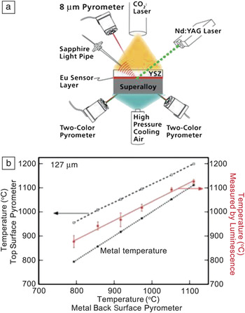
This temperature sensing methodology has recently been demonstrated using EBPVD 7YSZ TBCsReference Gentleman, Eldridge, Zhu, Murphy and Clarke30, Reference Eldridge, Zhu and Wolfe33, Reference Gentleman34 with an integrated luminescence sensing layer composed of europium doped YSZ at the TBC/bond-coat interface. The experimental setup is illustrated in Figure 5a.Reference Gentleman, Eldridge, Zhu, Murphy and Clarke30 A solid-state frequency doubled YAG:Nd laser emitting at 532 nm illuminates the center of the coating surface, while the high heat flux CO2 laser is used for heating the specimens under large thermal gradients. A sapphire light pipe is positioned to collect the excited luminescence signal during the testing. Figure 5b shows the luminescence sensor measured real-time interface temperature under various heat flux conditions, demonstrating the ability to collect luminescence from a thin embedded sensor layer in TBC systems under high temperature thermal gradients.
(a) Experimental setup for measuring the thermal-barrier coating (TBC)/metal interface temperature through the TBC by Eu luminescence under laser high heat flux thermal gradient tests.Reference Gentleman, Eldridge, Zhu, Murphy and Clarke30(b) TBC interface temperature measured as a function of TBC surface and metal back surface temperatures with various heat fluxes, for two electron beam physical vapor deposited coating thicknesses. A good correlation of the sensor measurements with the heat flux measurements has been observed with an embedded Eu-YSZ sensor at high temperature.Reference Gentleman, Eldridge, Zhu, Murphy and Clarke30, Reference Gentleman34

Infrared imaging
The key to extending the use of TBCs is assessing damage, especially sub-critical coating delamination, prior to coating failure. In particular, early detection of TBC damage also enables a part to be replaced and, possibly, repaired. The majority of non-destructive methods for this type of monitoring utilize spectral variations in the optical properties of YSZ. For instance, at 10.6 μm, the wavelength of CO2 lasers, YSZ is heavily absorbing, but it is translucent in the visible and near infrared (IR). One approach is to image local separations between the coating and alloy based on variations in reflectivity of thermal waves launched by pulse heating of the coating surface. The larger effusivity at the delamination than at the interface between the TBC and the underlying alloy locally causes a greater thermal reflectivity and hence higher image contrast, enabling an image to be formed of large delaminations. In the visible, YSZ is transparent but highly scattering. However, in the mid-IR, the scattering is reduced, enabling optical imaging of delaminations in both EBPVD and plasma-sprayed TBCs.Reference Eldridge, Spuckler and Martin35
Recently, it has also been demonstrated that with advances in IR focal plane array cameras, it is now possible to perform real-time, online near-IR monitoring of rotating blades during engine operation. This offers the prospect of increasing gas turbine operational reliability, especially by minimizing engine shutdown or outage time. In addition, with a link to component computer aided design (CAD) models, thermal design models can be validated by in situ temperature measurements. This is expected to enable better diagnosis and prognostics of component integrity for more advanced engine operation.
As the technology of focal plane imaging has become more sophisticated, the number, types, and pixels of array detectors have greatly increased. Together with more selective filtering capabilities, these detectors can more efficiently be matched to specific applications, improving measurement performance. When used with complex algorithms to provide real-time linearization and compensation of the detector output, higher precision temperature measurements become feasible. For instance, measuring the temperatures of high speed rotating components using focal plane technology requires very short integration (<3 ms) or the ability to have photons fill the focal plane to form a snapshot in microseconds and even nanoseconds, thus creating qualitative spatial detail of the rotating blade. In effect, every imaging pixel is a pyrometer. In a recent Siemens implementation, a telescopic lens system is used to image a portion of the blades onto a focal plane array over the spectral range of 0.9 μm to 1.6 μm, avoiding characteristic emissions from combustion from gas species, such as CO2 and H2O, while also maximizing the sensitivity of the array to the peak of the black body radiation from the blades.
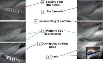
Radiation reaching the detector includes contributions from three sources: (1) radiation emitted from the surface of the turbine component being imaged, (2) reflected radiation included from particulates in the gas stream, as well as (3) radiation emitted from hot gases and particles in the field of view. A methodology was developed to overcome these hurdles and perform the surface temperature measurements. Figure 6 illustrates features that can be seen during engine operation using state-of-the-art focal plane arrays with advanced software imaging (see Figure 1 in the introductory article for an image of turbine blades). These include (a) TBC spallation on the leading edge of the blade as seen by the dark edge of the TBC, (b) local heating due to rubbing between two components—bright feature near rub, (c) local cooling at a blade platform—dark due to cooling air leakage, (d) platform TBC delamination, observed as bright/dark line corresponding to a buckled TBC, (e) overlapping cooling holes on the blade, where the dark cooling streams are not giving good coverage, and (f) a platform TBC crack observed as a faint bright line, verified by the visual picture shown in the inset in Figure 6f.
Example of turbine features that can be observed by an infrared camera during engine operation at 3600 rpm with gas path temperatures higher than 1200°C. Pictures are “still” frames of rotating blades. (a) Thermal-barrier coating (TBC) spallation on the leading edge of the blade as seen by the dark edge of the TBC; (b) local heating due to rubbing between two components—bright feature near rub; (c) local cooling at a blade platform—dark due to cooling air leakage; (d) platform TBC delamination, observed as bright/dark line corresponding to a buckled TBC; (e) overlapping cooling holes, where the dark cooling streams are not giving good coverage; and (f) platform TBC crack observed as a faint bright line.

One exciting development in inspection methods is combining thermal imaging with ultrasonics. The concept is to induce vibrations in a component or an array of blades, for instance, with an ultrasonic source and use a highly sensitive focal plane array to image the locations of frictional heating.Reference Han, Loggins, Zeng, Favro and Thomas36 This has recently been implemented, for instance, in the Siemens acoustic thermography system, SIEMAT, for the detection of cracks and kissing (detached) bonds in parts. Its attributes include high sensitivity to tight interfaces, the ability to see defects through coatings, and the ability to inspect components with minimal preparation.Reference Homma, Rothenfusser, Baumann and Shannon37, Reference Rothenfusser and Homma38 Post-processing algorithms are then used to assist in the identification of defects.
Summary and outlook
It is abundantly clear that testing and evaluation of thermal-barrier coatings (TBCs) is extremely challenging, yet TBC progress depends critically on our ability to test, evaluate, and monitor TBCs under conditions relevant to engine operation. New methods for measuring mechanical properties of TBCs will need to be developed with a deep understanding of TBC failure mechanisms. Thermomechanical fatigue and thermal gradient testing under realistic engine conditions are also needed to more accurately simulate TBC failure that is representative of what happens in operating engines. Sensing, nondestructive evaluation, and in situ monitoring of TBC health are critical for the intelligent operation of engines with maximum utilization of TBCs and to avoid catastrophic failure.