I. INTRODUCTION
High-strength Al–Cu–Mg alloys, such as 2024-Al and 2048-Al, are widely used in applications that require light weight, high fracture toughness, and high strength, such as aerospace, automotive, and armor systems. These alloys, however, do not generally perform well at high temperatures. Heat-resistant Al–Cu–Mg alloys such as 2219-Al and 2618-Al have, on the other hand, limited fracture strength and damage tolerance.Reference Eschbach, Solenthaler, Uggowitzer and Speidel1 The addition of small amounts of Ag to Al–Cu–Mg alloys, with high Cu-to-Mg ratios, results in the nucleation of thermally stable, platelike Ω precipitates on {111} planes of the aluminum matrix.Reference Polmear and Couper2 Moreover, Al–Cu–Mg–Ag alloys have less grain-boundary (GB) precipitation and therefore retain most of their toughness after age hardening, since they would be less susceptible to intergranular fracture.Reference Hono, Sano, Babu, Okano and Sakurai3, Reference Howe and Basile4 Al–Cu–Mg–Ag alloys can thus be tailored for high strength, temperature resistance, toughness, and damage tolerance, and an example of such an alloy is 2139-Al.Reference Cho and Bes5
The potential use of Al–Cu–Mg–Ag alloys for extreme loading conditions and applications is therefore predicated on identifying and understanding the deformation mechanisms related to increased strength and toughness. Once this understanding can be obtained, optimal trade-offs between the competing mechanisms of strength and toughness can be potentially achieved.
In this paper, we focus on an Ω precipitate embedded in an aluminum single crystal. We investigate how this Ω precipitate interacts with dislocations and dislocation densities under dynamic loading and how it affects the toughening and the strengthening of the alloy at different length scales. The effects of residual tensile strains at the tips of the Ω precipitate are also investigated to quantify its influence on the overall behavior of the alloy.
This paper is organized as follows: an experimental characterization of a deformed Ω precipitate is presented in Sec. II. An outline of the specialized FE approach is given in Sec. III, and its results are discussed in Sec. IV. The molecular dynamics (MD) simulation is then outlined and its results discussed in Sec. V. Finally, a summary of the salient conclusions is given in Sec. VI.
II. EXPERIMENTAL CHARACTERIZATION
The specimens investigated in this study were taken from a 1.5 in. thick 2139-T8 Al shot plate. The shot plate was impacted by 20 mm AISI 4340 steel fragmentation stimulating projectiles (FSPs) at velocities ranging from 813 to 1043 m/s. Impact was in accordance with the USADTC TOP 2-2-710 V50 test procedures at the Army Research Laboratory.Reference Cheeseman, Gooch and Burkins6
Transmission electron microscopy (TEM) was used to investigate precipitate deformation and dislocation interactions with the precipitates. Sample preparation methods were chosen so as to preserve the microstructure and not induce any damage. Waterjet cutting was used to section the material from the bulk plate. Further sectioning was accomplished using a low-speed diamond saw. TEM samples were prepared by twin-jet electrochemical polishing with a nitric/methanol mixture at 243 K. A JEOL 2010F equipped with a GATAN Image Filter was used for phase-contrast HRTEM imaging at 200 kV.
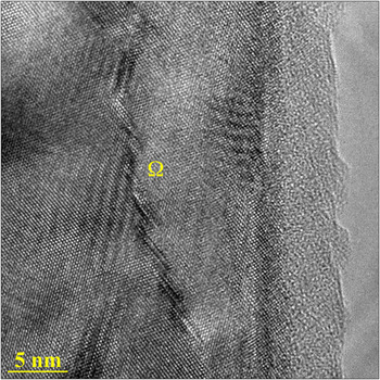
On average, Ω precipitates are 44 ± 1.8 nm in length, and less than 3 nm thick. Figure 1, taken from our earlier work,Reference Lee and Zikry7 shows the typical deformation of a thin Ω precipitate (approximately 1 nm thick) from the vicinity of the projectile. It is seen that the Ω precipitate has multiple cuts, due to multiple dislocations cutting through the platelet along its entire length; i.e., the deformation of Ω is not localized to a particular segment of the platelet, but forms instead a stepladder configuration as shown in Fig. 1. This observation under high strain rates is consistent with the mechanism of multiple shear cuttings of Ω suggested by Li and WawnerReference Li and Wawner8 for quasi-static experiments.
HRTEM image of a deformed Ω platelet in a 2139 Al impacted plate. The Ω platelet is cut multiple times by dislocations cutting through it, forming this stepladder configuration.

III. FINITE ELEMENT APPROACH
A. Crystalline plasticity
Constitutive formulations for rate-dependent multiple-slip crystal plasticity, which are coupled to evolutionary equations for dislocation densities, have been used. For a detailed presentation see Orsini and Zikry,Reference Orsini and Zikry9 Zikry and Kao,Reference Zikry and Kao10 and Ashmawi and Zikry.Reference Ashmawi and Zikry11
In that formulation, the velocity gradient is decomposed into a symmetric deformation rate tensor Dij and an antisymmetric spin tensor Wij. Dij and Wij are then additively decomposed into elastic and plastic components as

The inelastic parts are defined in terms of the crystallographic slip-rates as

where α is summed over all slip-systems, and  and
 are the symmetric and antisymmetric parts of the Schmid tensor, defined with respect to the material frame.
The rate-dependent constitutive description on each slip system can be characterized by a power-law relation as

where  is the reference shear slip rate that corresponds to a reference shear stress
 , and m is the rate sensitivity parameter. The reference stress that is used here is a modification of widely used classical formsReference Mughrabi12 that relate the reference stress to a square-root dependence on the dislocation density (ρim) as:

where  is the static yield stress on slip system (α), G is the shear modulus, nss is the number of slip systems, b (ρ) is the magnitude of the Burgers vector for slip system (ρ), and the coefficient a αρ is a slip-system interaction coefficient. T is the temperature, T 0 is the reference temperature, and ξ is the thermal softening exponent.
For a given deformed state of the material, the dislocation structure, of total dislocation density ρ(α), is additively decomposed into a mobile and an immobile dislocation density,  and
 respectively, as

It is assumed that during an increment of strain, there ensues a change in the dislocation structure. The balance between generation and annihilation of dislocation densities as a function of strain is thus taken as a basis for the following equations, which describe the evolution of mobile and immobile dislocation densities


where g sour, g minter, g recov, and g immob are coefficients for: generation of mobile dislocation densities, trapping of mobile dislocations by dislocation–dislocation interactions, rearrangement and annihilation of immobile dislocations by recovery, and immobilization of mobile dislocations, respectively. For a determination of these coefficients, see Kameda and Zikry.Reference Kameda and Zikry13 ΔH is the enthalpy of activation of plastic deformation, and k is the Boltzmann constant.
B. Precipitate crystallographic representation and orientation
As seen from the preceding section, the crystalline-plasticity constitutive formulation requires the identification of the specific crystal structure, slip systems, and mechanical properties. For Al–Cu–Mg–Ag alloys, the Ω phase (Al2Cu) has been observed to have an orthorhombic structure (Fmmm) as noted by Knowles and Stobbs.Reference Knowles and Stobbs14 In this study, however, the Ω phase has been modeled by the alternative I4/mcm structure,Reference Garg and Howe15, Reference Ringer and Hono16 which is only a slight perturbation of Fmmm, but is identical to the θ crystalReference Wang and Starink17 whose slip systems have been identified experimentally.Reference Bonnet and Loubradou18, Reference Ignat and Durand19 The associated rational orientation relations for I4/mcm Ω with the aluminum matrix are used.Reference Wang and Starink17
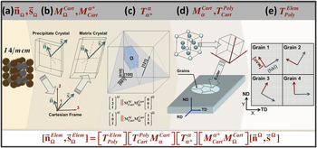
The method used to align the crystal lattice with FE or global axes is the same as that developed in Ref. 20 and is here only outlined briefly. First, Miller indices of planes and directions that define orientation relations between precipitates and matrix were defined. The slip directions and planes for the matrix and precipitates are defined in fractional coordinates. Since the precipitates are noncubic, the vectors defining slip-plane normals are not equivalent to their Miller indices, and the normals can be obtained by a reciprocal lattice construct. The vectors are then mapped from the precipitate space to the matrix space. This is achieved by the transformation sequence  , where
 transforms a vector in the precipitate (e.g., Ω) to a vector in a Cartesian frame, and
 maps the transformed vector from the Cartesian frame to the matrix crystal. The vectors are then aligned according to orientation relations by matrix
 , followed by another transformation
 mapping vectors from the matrix space to a Cartesian space if necessary (i.e., if the matrix crystal is noncubic). Euler angles can then be assigned to the matrix grain to align the crystal lattice with respect to the polycrystalline sample. The sample is then aligned with the element frame by
 .Reference Elkhodary, Sun, Irving, Brenner, Ravichandran and Zikry20 This sequence is outlined in Fig. 2.
Illustration of slip vectors (nΩ, sΩ) transformation sequence. (a) Slip systems are identified in fractional coordinates. (b) Slip system vectors are transformed from precipitate space to matrix space. (c) Resulting precipitate vectors are aligned in accordance with the orientation relationships with the matrix crystal. (d) Oriented slip vectors are mapped to the axes of the polycrystalline aggregate by specifying the Euler angles. (e) Vectors are mapped from the polycrystalline aggregate to the element axes.

IV. FINITE ELEMENT RESULTS AND DISCUSSION
A. Finite element model
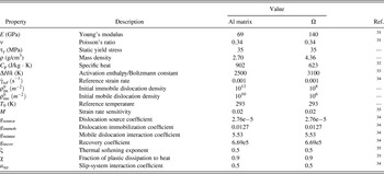
The behavior of an Ω precipitate in an aluminum matrix under large compressive strains and strain rates was investigated. The material properties used in this study are summarized in Table I. For nondimensionalization, the following characteristic quantities were used: Young’s modulus of the matrix (E), the elastic dilatational wave speed in the matrix (c), Burgers vector in the matrix (bv), and room temperature (T ref). The nondimensionalized quantities are listed in Table II.
Material properties for Al, Ω, and θ′ used in finite element simulations.

Nondimensionalization scheme used in the finite element simulations.

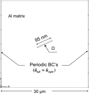
The matrix crystal was assumed to have dimensions of 0.5×0.5 μm as shown in Fig. 3. An Ω precipitate was placed at the centroid of an aluminum crystal, with its thickness and long directions aligned in accordance with its rational orientation relationship to the matrix. The precipitate size was taken as 4.5 × 95 nm, which is consistent with the physically observed scales from the TEM characterization images.Reference Elkhodary, Lee, Cheeseman, Brenner, Zikry, Misra, Balk, Huang, Caturla and Eberl21
Model of the aluminum crystal with an embedded Ω precipitate. The aluminum matrix is 0.5 × 0.5 μm and the Ω precipitate is 4 × 95 nm. The left and right boundaries are periodic, the upper edge is subjected to an applied strain rate of 50,000 s−1, and the lower edge is fixed.

The aluminum crystal was assigned Euler angles of (35°, 70°, 30°) in the Bunge convention with respect to the sample axes (rolling direction, normal direction, transverse direction), consistent with aluminum plates.Reference Polmear22 Periodic boundary conditions were applied for a two-dimensional (2D) plane-strain deformation mode (Fig. 3). For representative high strain-rate behavior, results for an applied strain rate of 5×10⁴ s−1 is presented. A convergent mesh of 4500 four-node bilinear plane-strain elements was used with one-point integration and enhanced assumed-strain hourglass control.
B. Dislocation-density evolution
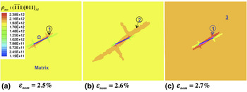
The Al/Ω interface is a source of dislocation densities. Figure 4(a) shows the generation of dislocation densities in the  slip system from the tips of the Ω precipitate, labeled as step 1. Figure 4(b) shows the propagation of a dislocation density level of fixed value along the interface and into the matrix (labeled 2). The propagated dislocation density is predominantly aligned with, but also normal to, the Ω broad face. Figure 4(c) shows the same dislocation density spread uniformly across the matrix (labeled 3). It also shows the generation of a new dislocation density at the tip (labeled 1), which will then follow the prior sequence: (1)–(3). We note that sequence (1)–(3) varies in duration with applied strain; however, it is typically rapid, spanning small increments in strain. For example, the increment of strain is 0.2% in Fig. 4. This result indicates the rapid propagation of dislocation densities from the tips of the Ω precipitate along its entire broad face, prior to spreading into the matrix. This result is also consistent with that for dislocation evolution obtained by MD calculations (Sec. V). We note that the Ω broad face is always aligned with a habit plane from the {111} matrix planes, which are also slip planes for the matrix, hence the favorable propagation of dislocation densities along the Ω broad face. For precipitates aligned differently, e.g., θ′ precipitates, whose habit plane is a {010} matrix plane,Reference Elkhodary, Sun, Irving, Brenner, Ravichandran and Zikry20 propagation of dislocation densities along the broad face would not be as favorable. This rapid and preferential propagation of dislocation densities along the Ω broad face permits a rapid distribution of deformation along its entire length, without localizing to a particular segment of the precipitate. This result can explain the multiplicity of shear cuttings of thin Ω precipitates observed in the TEM image, Fig. 1, which indicates that the Ω platelet is sheared more or less uniformly along its length (smearing out localization at the atomic level where dislocations cut). In contrast, for instance, θ′ precipitates exhibit plastic buckling,Reference Elkhodary, Lee, Cheeseman, Brenner, Zikry, Misra, Balk, Huang, Caturla and Eberl21, Reference Embury23 where deformation essentially localizes to a segment of the precipitate.
(a) Generation of dislocation densities at the tip of the Ω platelet. This marks the beginning of a sequence (labeled 1). (b) Propagation of dislocation densities aligned with and normal to the Ω broad face (labeled 2). (c) Dislocation densities spread uniformly into the matrix (labeled 3); also, generation of new dislocation densities at the tip of Ω (again, labeled 1).

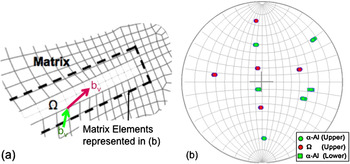
As shown in Fig. 5(a), because of the difference in crystal structure between Ω precipitates (I4/mcm) and the matrix (face-centered cubic; fcc), slip is incompatible; i.e., for plasticity to traverse a precipitate, a change in slip vectors is needed. In Fig. 5(b), the circles correspond to the slip vectors in the matrix crystal adjacent to the precipitate, while the circles correspond to those in Ω, the stereographic projection being centered on the load axis. It is clear, therefore, that large changes in Burgers vector orientations (as well as lengths) are required for plasticity to traverse the precipitate. Because of the intensive interspersion of Ω precipitates in every matrix crystal in the alloy, and as a result of this incompatibility of slip, Ω precipitates act as an obstacle to plastic deformation and will therefore also result in alloy strengthening. Furthermore, because of the multiple shear cuttings of Ω, the deformation is not localized at the macroscale, and alloy ductility is improved.Reference El-Khodary, Lee, Sun, Cheeseman, Brenner, Zikry, Raabe, Kalidindi, Radovitzky and Geers24
(a) Close-up view of the matrix and Ω elements used in stereographic projection (b). (b) Stereographic projection of slip directions for matrix and Ω elements, looking down the loading axis. Circular symbols are on the upper hemisphere, and square symbols are on the lower hemisphere.

C. Effect of unrelaxed misfit strains at the Al/Ω interface
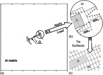
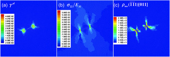
Aluminum alloys with Ω precipitates have large unrelaxed misfit tensile strains in the thickness direction of the Al/Ω interface, which are localized at the tips of Ω precipitates, where the interface is semicoherent. On the basis of lattice misfits between Ω and Al, these tensile strains were estimated to be as large as 8% at the tip of the Ω platelet,Reference Fonda, Cassada and Shiflet25 while experimental measurements revealed these tensile strains could vary with platelet thickness and attain values up to 30%.Reference Hutchinson, Fan, Pennycook and Shiflet26 It has never been quantified how these tensile strains can further affect behavior at high strain rates. To investigate the effects of these tensile strains on precipitate deformation, unrelaxed tensile strains were introduced in the finite element model as an initial state, which we model as follows. As shown in Fig. 6, the finite element model constitutes initially of the Al matrix, without attaching the Ω precipitate. Its surfaces, those that enclose the Ω precipitate, are pulled on with linearly varying displacement profiles as shown [Fig. 6(b)]. In this manner, we impart a nominal tensile strain in the matrix that localizes near the tip of the Ω precipitate, and which decays to zero within 50 Burgers vectors from its tip. Having induced this tensile strain distribution in the matrix, the Ω precipitate is then attached to the Al matrix by application of tie constraintsReference Hibbitt, Karlson and Sorensen27 along their common surfaces, with node-to-node correspondence, as shown by the dotted lines in Fig. 6(c). Once tied, the tensile strains in the matrix redistribute to the precipitate, and the matrix–precipitate system finds a new equilibrium, which corresponds to the initial state we use to represent the unrelaxed misfit strains. Figure 7 shows this initial state, corresponding to a nominal tensile strain of 5%. A corresponding maximum shear strain of 5% occurs at the Ω precipitate tips [Fig. 7(a)]. Associated with this strain is the normal tensile stress shown in Fig. 7(b), with a maximum value of 350 MPa. A corresponding localized increase in dislocation densities occurs at the tip of the Ω precipitate for system  , as shown in Fig. 7(c). This local increase of dislocation densities is consistent with the presence of misfit dislocations at a semicoherent interface.Reference Fonda, Cassada and Shiflet25, Reference Hutchinson, Fan, Pennycook and Shiflet26
(a) Application of 5% tensile strain on the matrix surfaces at the Al/Ω interface. (b) Close-up view of the surfaces at Al/Ω interface showing the applied displacement profile near the Ω platelet tips, which decays over a span of 50 Burgers vectors (bv) away from the tips. (c) After the load is removed, the surfaces of Ω and Al are fixed together by application of tie constraints as shown (dotted), with node-to-node correspondence.

The state of the matrix and Ω corresponding to the load described in Fig. 6. (a) A maximum plastic shear slip of 5% results at the tips of Ω. (b) The associated normal tensile stress (σ22/E Al), with σ22 = 350 MPa maximum value. (c) The corresponding mobile dislocation densities on slip system  with a maximum value of 2.38 × 10¹² m−2

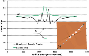
Figure 8 compares accumulated plastic shear slip in an initially strain-free model with that in the “prestrained” model (i.e., the model with unrelaxed misfit strains, or Fig. 7, as its initial state). The curve is for a nominal compressive strain of 7% along an evaluation path that cuts through Ω, as is shown in the inset. It is clear that the prestrained matrix undergoes less shear slip on average and that slip is less localized. The fluctuations along the path in the prestrained condition are related to the initially nonuniform dislocation densities along the path, as can be seen from Fig. 7(c). It is also seen that the precipitate undergoes shear slip that is more comparable with the surrounding matrix for the prestrained condition than for the strain-free condition. A prestrained interface therefore has the effect of uniformly distributing plastic deformation and inhibiting localized behavior.
Comparison of plastic shear slip (γpl) at a nominal compressive strain of 7% along an evaluation path that cuts through Ω as shown in the inset.

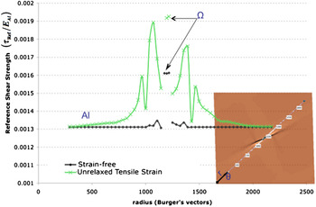
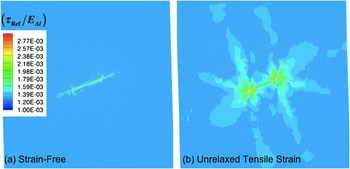
Figure 9 shows the corresponding comparison of the reference shear strengths (τref) of the crystals [Eq. (4)]. It is seen that τref is on average higher for the prestrained condition than the strain-free condition. Moreover, the shear strengths in Ω and the adjacent matrix are comparable. The observed fluctuations in τref are again related to the nonuniformity of dislocation densities at the precipitate interface [Fig. 7(c)]. The Ω precipitate, therefore, is less of a local stress raiser in the prestrained condition. This results in the increased homogeneity of strengthening seen in Fig. 10.
Comparison of reference shear strength (τRef/E Al) at a nominal compressive strain of 7% along an evaluation path that cuts through Ω as shown in the inset.

Contours of reference shear strength (τRef/E Al) for the cases (b) with and (a) without an initial strain.

V. MOLECULAR DYNAMICS SIMULATION OF DISLOCATION EMISSION AND PLASTICITY FROM AN Ω PRECIPITATE
Our finite element model has gleaned insights into the mechanisms of dislocation density generation and propagation at the Al/Ω interface. We further resolve to atomic detail this Al/Ω interface, by means of molecular dynamics, to examine the nucleation and evolution of discrete dislocations at the interface, while taking into consideration interface coherency and energies, and for a comparison with our continuum finite element predictions for dislocation densities.
A. Molecular dynamics model
The extreme strain rate produced by shock compression, which typically corresponds to shock front speeds of the order of km/s, enables a time scale at which detailed atomic dynamics can be captured by MD simulations. Thus, we carried out MD simulations to characterize atomic-level mechanisms of plastic deformation, specifically dislocation nucleation and growth, due to shock loading of an Ω precipitate.
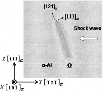
A model, with the orientations illustrated in Fig. 11, was used to study dislocation nucleation and motion under uniaxial planar shock loading. The model is composed of a Ω precipitate embedded in an aluminum matrix. The simulation cell contains 1.5 million atoms and has dimensions 3.4 × 84 × 90 nm3 in the respective  ,
 , and [111]Al directions. Periodic boundary conditions are applied in the
 and [111]Al directions, while the system was assumed finite in the
 direction. The Ω platelet is aligned coherently on the
 habit plane and is composed of 4 × 80 × 6 (~3.4 × 40 × 5.1 nm3) unit cells of the Ω crystal in the [010]Ω
 , [100]Ω (//[121]Al), and [001]Ω
 directions. This model represents an Ω precipitate with dimensions in the [100]Ω and [001]Ω directions that are close to the actual dimensions observed in 2139-Al alloys, but that are periodic along the [010]Ω direction. To generate a planar shock front, the relative positions of the Al atoms in a two-unit-cell thick region at one end of the simulation cell along the [111]Al direction (the right side of the structures illustrated in Fig. 11) were held constant, while translating these atoms at a constant velocity toward the opposite end of the system. In this orientation, the planar shock front propagated in the
 direction with an angle of ~70.5° with respect to the Ω platelet.
Structural model used in the molecular dynamics simulation.

B. Molecular dynamics results
An embedded-atom method (EAM) inter-atomic potential developed by Adams and coworkersReference Liu, Xu, Foiles and Adams28 was used in the simulations because it gives a reasonable description of the Al, Ω, and Al/Ω interface structures and energies compared with our previous first-principles calculations.Reference Sun, Irving, Zikry and Brenner29 However, a slight modification in the long-range part of the Al–Cu interaction pair function was necessary to eliminate nonphysical Al/Ω interface structures predicted by the original EAM potential.Reference Sun, Irving, Zikry and Brenner29 Using this potential, the simulation samples were first equilibrated at 300 K and then compressed by shockwaves generated at different piston speeds.
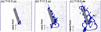
Configurations from the atomic simulations that show typical dislocation dynamics created by the shock loading are illustrated in Fig. 12. The position of the shock front, which travels from right to left, is indicated by the arrows. To better visualize the dislocations, only atoms with local symmetries different from bulk Al are shown, as given by a centro-symmetry parameter.Reference Kelchner, Plimpton and Hamilton30 When compressed by elastic planar shockwaves, Fig. 12(a) shows that dislocation nucleation is heterogeneous, since dislocations are initiated at the Al/Ω interfaces. This is consistent with our prior first-principles calculationsReference Sun, Irving, Zikry and Brenner29 that the Al–Al bonds at the Al/Ω interfaces are weaker than both the Al–Al bonds in bulk aluminum and the Al–Cu bonds in the Ω phase.
From the molecular dynamics trajectory for shock loading. The shock is traveling from right to left with speed 0.9 km/s. Atoms associated with stacking faults created by dislocations are shown and are identified by a centro-symmetry parameter. Bulk aluminum is not shown. The Ω precipitate is marked using a gray bar. The scattered points in the Al arise from thermal noise. The vertical arrow marks the boundary between the uncompressed and shocked material.

In addition, dislocations were found to nucleate at the ends of the Ω platelet first and are more active than at the broad face of the Al/Ω interface, which is consistent with the FE results. This is due to the incoherent interface at the Ω plate edge being less stable than the coherent Al/Ω broad face interface. After dislocations are nucleated [Fig. 12(a)], they propagate along the Ω broad face [Fig. 12(b)], before spreading into the Al matrix [Fig. 12(c)]. This confirms the sequence of generation and propagation of dislocation densities that the FE simulation predicted (Fig. 4).
Moreover, as seen from Fig. 12, there are dislocation dynamics on both sides of the Ω phase. This phenomenon is sensitive to the shock condition and Ω plate thickness (i.e., the piston speed and the thickness of the Ω phase in the [001]Ω direction). In general, increasing the shock speed or decreasing the Ω thickness induces dislocation nucleation on both sides of the precipitate. It can also be seen from Fig. 12 that there are multiple active slip systems involved in the stacking fault emissions from the interfaces, and the propagation is accompanied by complicated growth and annihilation processes.
VI. CONCLUSIONS
The FE microstructurally based model indicates that dislocation densities generated from the tip of an Ω precipitate rapidly propagate, first along the Al/Ω interface, then into the matrix. The experimentally observed stepladder deformation of Ω can be understood in terms of this mechanism, which rapidly propagates dislocation densities along the favorably oriented Al/Ω interface, thus leading to the uniform distribution of shear cuttings of the Ω precipitate. This rapid generation–propagation mechanism was also consistent with the MD simulations for discrete dislocations, which accounts for the Al/Ω interface coherency and energies. Finally, along with this mechanism, the unrelaxed tensile strains at the Al/Ω interface have the effect of inhibiting localization of plastic strains and stresses under impact loading and result in higher strength of Al–Cu–Mg–Ag alloys.
ACKNOWLEDGMENT
Support from the Army Research Office and JIEDDO is gratefully acknowledged.