I. INTRODUCTION
A network of surface movement radar (SMR) is normally used as the basis for advanced-surface movement guidance and control system (A-SMGCS) design for large airports [Reference Galati, Naldi and Ferri1, Reference Galati, Ferri, Leonardi, Magarò and Gasbarra2]. Various types of radar have been suggested as candidates for SMR following both the main requirements of such systems and the capabilities of current radar developments.
In Section II we describe the A-SMCGS functions and the SMR requirements [3]. Most of the current SMRs work at the X-band; this implies the use of large antennas, with a rotation speed of 60 RPM. In many practical situations, the airport surface to be covered is limited to the runways and their neighboring areas within an angle around 180°. Therefore the new idea is to substitute the rotating antenna in conventional SMR by a set of nonmoving synthetic aperture antennas (SAAs) to cover a defined area. The number of SAAs to be used depends on the area to be covered.
In Section III we present the main idea [Reference Lukin4] and formulate general requirements to its basic elements. In Section IV we give a detailed description of a type of SAA developed in LNDES IRE NASU [Reference Lukin4, Reference Lukin5], which enables avoiding rotating antennas that are usually used in SMRs.
In Section V we also present results of the theoretical and experimental evaluation of potential capabilities of noise radar technology (NRT) [Reference Lukin6–Reference Lukin8] for SMR design and development.
II. A-SMCGS FUNCTIONS AND REQUIREMENTS IN SMR
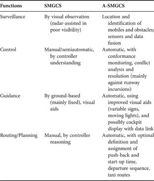
The capacity of an A-SMGCS is defined as the maximum number of simultaneous movements of aircraft and vehicles that the system can safely support within an acceptable delay related to the runway and taxiway capacity of a particular airport. The A-SMGCS provides the following functions (as described in Table 1 where the functions are compared with SMGCS): surveillance, control, guidance and routing/planning of aircraft and vehicles in order to maintain the airport capacity under all local weather conditions, while maintaining the required level of safety.
Comparison functions of SMGCS with A-SMGCS.

SMR is the main sensor in A-SMGCS and it must have the following characteristics [Reference Galati, Naldi and Ferri1, Reference Galati, Ferri, Leonardi, Magarò and Gasbarra2]:
1. High accuracy and resolution capabilities in range and azimuth measurements on the entire airport surface so as to recognize the shape and orientation of the target (features extraction and classification/identification). The system shall be able to detect objects (whether fixed or mobile) whose radar cross section is 1 m2 (typical value for the X-band) with a 90% probability even in severe weather (e.g. with a rainfall rate up to 16 mm/h). The resolution shall be better than 10 m (aiming at a target value of 3–6 m) to allow for subsequent image processing in order to assess both the size and the orientation of the vehicle.
2. The coverage area has to be large enough to overlap the airport surface (runways, taxiways, and Apron). A single radar can have problems with shadowing; therefore a multi-radar network is an advanced solution for future systems.
3. The high resolution imposes a pulse width of about 40 ns and an antenna mainlobe width less than 0.4° (desirable values: 20 ns and 0.2°).
4. The data refreshing period shall not be greater than 1 s.
5. The system shall be able to track up to 400 objects at the same time, with a processing delay (latency) lower than 100 ms.
6. The object location shall be measured with a precision better than 5 m. Velocity shall be measured for both cooperating and noncooperating targets with an accuracy better than 2.5 km/h for speeds in the range 5–100 km/h.
7. The system shall be able to visualize small-sized objects (such as suitcases), which can accidentally lie on the ground.
8. The installation of the antenna and of the radar shall be as easy as possible. Low transmitted power and small-sized antennas reduce the installation requirements and cost.
9. Electromagnetic compatibility has to be guaranteed with other radar and communication systems in the airport.
10. There shall be full respect of ICAO and EUROCAE standards and integration purposes in the A-SMGCS system [3].
The main problems in SMR are (i) control of false alarms, especially in clutter, (ii) rain attenuation at highest frequencies, and (iii) plot extraction [Reference Galati, Magarò, Leonardi and Cavallin9], as aircraft targets have extensions up to 60–70 m as compared to radar resolution cells of 6 m × 0.4° (3 m × 0.2° in high-resolution radar) and occupy hundreds of resolution cells. The resulting “target splitting” is a well-known phenomenon in SMGCS. Finally, the constant false alarm rate (CFAR) threshold is a key element of the plot extraction process. It must guarantee a limited detection loss (e.g. below 2 dB) and satisfy the conflicting requirements of detecting (a) both extended targets (e.g. aircraft) and small targets (e.g. persons, small vehicles), (b) both fixed and moving targets and (c) in small, fixed clutter environment, in medium, slowly varying clutter, and in strong, quickly varying clutter.
The above requirements can be met with a network of lightweight, compact, millimeter-wave (W-band, 95 GHz) radars [Reference Galati, Naldi and Ferri1]. The millimeter-wave band has the following advantages:
– Reduced equipment size and simpler installation.
– Easy integration in an existing airport traffic control system.
– Low average transmitted power.
– Larger radar cross-section (RCS).
– Detection of any kind of target.
– Detection and imaging of aircraft (bearing angle extraction).
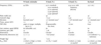
A first demonstrator of SMR working at the W-band was developed early in 1995 in Oerlikon Contraves Italiana (OCI) and was tested by the end of 1996. Two identical radars have been operating for many months in Frankfurt airport and in Venice airport, respectively. The basic characteristics of the W-band radar are shown (nominal values) in Table 2 in comparison with other systems operating at the X- and Ku-bands.
Main characteristics of SMR.

*Standard uses magnetron of 25 kW; optional employs magnetron of 30 kW.
†A RCS of 1 m2 has been supposed at the X-band, 10 m2 at the W-band.
‡In bad weather condition Rmax is unknown.
§RCS of 2 m2.
Evaluation of the coverage performance of the W-band miniradar network has been carried out for several Italian and European airports [Reference Galati, Ferri, De Fazio and Magarò10]. The number of miniradar sensors necessary to perform complete coverage of the airport layouts varies from 1 to 4 with a typical value of 2 for a medium-sized airport such as Marco Polo in Venice.
III. A NEW APPROACH TO SMR DESIGN
As may be seen from the above points 1–10 (Tables 1 and 2), there are many challenges in A-SMGCS design if one wants to use the conventional radar approach. In particular, it is rather difficult to achieve simultaneously high range resolution and environmentally safe performance of SMR with working range from 200 to 5000 m to be used in A-SMGCS. On the other hand, the low cost required for SMR is difficult to combine with the desirable flexibility of radar performance, which may enhance operation and performance efficiency of the radar, i.e. coherent processing of radar returns and clutter suppression. High azimuth resolution requires relatively large dimensions of the radar antenna to be rotated with 60–120 RPM. The idea of shortening the radar signal wavelength creates the problem of high rate attenuation of the signal under rain or snow weather conditions. For instance, at the W-band (95 GHz) experimental results [Reference De Fazio, Ferri, Galati and Leonardi11] show a range coverage up to 3000 m in clear weather, 2000 m with 50 m fog visibility, better than 1200 m in rain (at the rainfall rate of 16 mm/h, as from EUROCAE/ICAO specifications and recommendations).
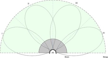
Many challenges in the design of efficient SMR may be solved in the novel concept suggested in [Reference Lukin12], which in general is based on the application of a ground-based synthetic aperture radar (GB SAR) with a high rate of SAR image generation for real-time surveillance of an airport surface area. This idea may be implemented with the help of a new antenna named SAA [Reference Lukin4, Reference Lukin5] in combination with SAR imaging technique and NRT [Reference Lukin6, Reference Lukin7]. Fast motion of a resonant radiating slot along a real aperture is a distinguishing feature of the SAA suggested. Section IV describes SAA in more detail. This approach enables avoiding the use of the rotating antenna of conventional SMR and applies, instead, a set of static antennas, such as SAA, to cover the area of interest. The number of SAAs to be used depends on the area to be covered (basically, its azimuthal extent) and on the desirable/available power of the transmitted signal. Figure 1 shows schematically an example of such coverage for a half-plane area using four SAAs: a coverage of 180° in azimuth is well suited to many SMR installations.
Coverage of the airport area with four SAAs.

However, depending on the working range and azimuth resolution required, the area of interest may be covered using a different number of SAAs. We have evaluated, for instance, that in case of not high azimuth resolution (5 – 10 m) at 3 km range and a viewing angle of 90° one may use one or two SAAs. On the other hand, in case of shorter range, but wider viewing angle, one has to apply up to four antennae to obtain better azimuth resolution and keep the transmitted average power below 5 W in the Ka-band. Many other options of SMR may be designed with performance dependent on the area to be monitored, working range, and azimuth resolutions. Below we describe realistic ways of this concept implementation for two different options.
IV. SYNTHETIC APERTURE ANTENNA TECHNIQUES
The basic idea of the suggested SAA consists of the following [Reference Lukin4]. For antenna beam forming and scanning, we use the principles of a 1D antenna array (AA), but with radiation/reception of electromagnetic pulses at each position of a single, moveable radiating/receiving element rather than simultaneous radiation/reception by all elements of the 1D-AA, as is usual. In other words, we use the concept of synthetic aperture radar being applied to the 1D-AA aperture. Generally, this approach enables application of various types of radiating elements and methods for its motion implementation along the antenna aperture. The following parameters are of major interest: antenna beam width, number of beam positions, antenna pattern sidelobes, and time of full scan. In the scanning antenna suggested, the beam width is defined by its real aperture, while the number of beam positions is defined by that of measurement positions for the radiating element. The sidelobe level will depend on the phase–amplitude distribution (weighting function) along the real aperture of the antenna. Finally, the time of full scan is defined by both the radiating element shift time to a neighboring position and the numbers of those positions. The above shift time in the antenna suggested may be done so short that in real applications it should be increased to provide the required data acquisition time at each position if transmitted power is not sufficient. It is obvious that for implementing a full scan in real-time scale, one has to perform both range and azimuth compressions in quasi-real-time scale. For instance, for a 30 m/s velocity, a typical speed of surface traffic, one resolution cell of 6 m will be passed by 0.2 s, which makes it possible to upgrade the frame up to five times and enables watching the smooth motion of such an object.
LNDES Institute has designed three types of synthetic aperture scanning antennas.
The first type of SAA uses realization of straight-line motion of the radiating slot as shifts of the cross-point of a straight line and a helical line when the latter is rotated. This version of scanning antennas has been tested jointly with AeroSensing Radar System, GmbH [Reference Lukin4]. For more details see [Reference Lukin4, Reference Lukin, Mogila, Galati and Pavan13].
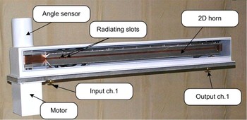
In the second technical approach as a real aperture antenna, one has to use a waveguide with a not-radiating half-wavelength longitudinal slot in its wider wall (Fig. 2). When covering this wall with a metallic tape having a half-wavelength transverse slot, one provides the condition for resonant radiation of the wave traveling inside the waveguide.
SAA for Ka-band GB SAR using the motion of a radiating slot along a waveguide with open wall (the waveguide is beyond copper tape).

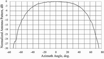
Figure 3 shows the antenna pattern of the above resonant slot in the azimuth plane, which gives us the hope of obtaining a rather wide observation angle for the suggested SAA.
Normalized antenna pattern of a single radiating resonant slot in a sliding slot antenna.

In order to enhance SAA efficiency, one has to place a short circuit at the proper distance from the radiating slot. The tape may be self-connected into a ring and rotated with a given speed. Scanning rate depends on the tape ring rotating speed and also may be rather high given a properly fast SAR processor. Unlike the previous case, this antenna does not need a rotary joint.
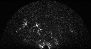
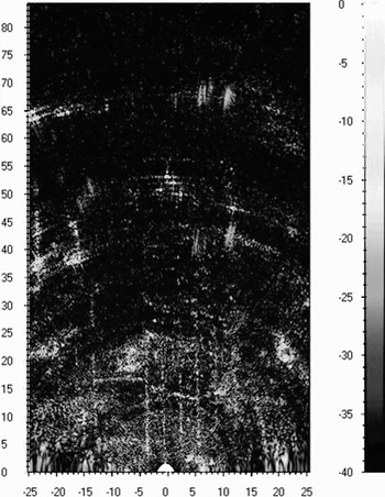
One frame of the real-time video generated with the help of this antenna is presented in Fig. 4. It is seen from Fig. 4 that the antenna designed enables scanning of a virtual antenna beam within the azimuth sector of ±65°. The tests carried out showed excellent results concerning its suitability for scanning antenna design on the basis of the aperture synthesizing principle.
Ka-band image obtained with the help of a sliding slot antenna: the viewing angle is about 130°.

In the previous architectures, moving parts or rotary joints are present. In the third type of scanning antenna, a virtual shift of the radiating element is performed [Reference Lukin5] via electro-mechanical switching of radiating elements that form a 1D array. The antenna is made by a waveguide with a linear array of equally spaced resonant radiating slots. Each slot is shielded by a three-state-screening strip (TSSS) having three different states: (1) open, (2) close, and (3) choke. The first/second state is used to open/close each radiating slot according to the control signal, while the third state is used to stop propagation of the feeding wave through the waveguide to enhance the radiation efficiency. Flip-flop operation is to be implemented with help of electromechanical switches, e.g. a combination of springs with electro-magnets. A linear virtual motion of the radiating slot is performed via switching of the TSSSs, thus enabling for each slot a sequential alternation of the following states: choke state, open state, and close state. The scanning rate of that antenna depends on the switching time of the electromechanical TSSS. A similar design may be implemented for patch antennas. With this aim, one has to prepare a linear array of radiating patches at an upper row and choke patches at a lower row while the feeding strip line is to be placed between them. Each patch should be fed through a flip-flop switch. A linear virtual motion of the radiating patch is performed via connecting/disconnecting the radiating patches and choke patches in a way similar to that in the previous case: (1) “radiating patch disconnected” and “choke patch connected”, (2) “radiating patch connected” and “choke patch disconnected”, and (3) “radiating patch disconnected” and “choke patch disconnected”. For providing high efficiency and high decoupling of the radiating patches, one has to use either MEMS switches possessing small losses, low power consumption, and high rate isolation, or electromechanical flip-flop switches possessing similar performance. The design of an SAA of the third type is in progress.
We have shown the potentialities of the new type of antenna; specific choice of the SAA to be used in SMR depends on its required performance.
V. NOISE RADAR TECHNOLOGY FOR SMR
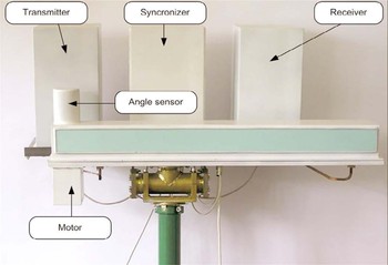
To validate the approach suggested, the ground-based noise waveform SAR (GB NW-SAR) has been developed [Reference Lukin8] on the basis of the above second-type antennas and Noise radar technology (NRT) [Reference Lukin6, Reference Lukin7, Reference Ferri, Galati and Pavan14]. Its general view is shown in Fig. 5.
A noise waveform (NW) with a wide and smooth enough power spectrum, having fast decay of correlations, enables one to perform simultaneously the high rate signal compression, its optimal reception, and minimization of range sidelobes. Besides, the ambiguity function of noise radar has no additional maximums, while for periodic waveforms this is always the case. From that, particularly, it follows that there is no contradiction for the NRT when providing the optimal conditions for simultaneous measurements of target distances and velocities; no theoretical limitations on the unambiguous working range; no needs in high peak power in the transmitted signals for a given working range. Besides, NR has excellent LPI and EMC performance enabling its simultaneous operation within the same area. The main performance of the Ka-band SMR on the basis of developed GB NW-SAR [Reference Lukin8] is as follows: working range 200–5000 m; resolution cells 1.2 m × 0.3°; average transmitted power 5–12 W; peak power 10–24 W for 50% duty cycle; antenna aperture ~1 m; full scan time 0.05 s. It is seen that a new concept enables the design of SMR with essentially enhanced performance compared to conventional radar: no need for a rotating antenna; low level of transmitted power; high rate of radar image refreshment given quasi-real-time SAR imaging. The latter is to be implemented on the basis of FPGA or cell processor technologies.
General view of Ka-band GB NW-SAR for near-range surveillance.

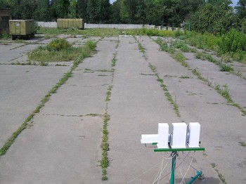
The GB NW-SAR has been tested for short-range imaging with off-line processing. The picture of the mapped area is presented in Fig. 6, while its SAR image is shown in Fig. 7.
Photograph of GB NW-SAR and mapped area.

SAR image of the area shown in Fig. 6 generated with the help of Ka-band GB NW-SAR. The numbers at the axis are given in meters.

One may easily identify corner reflectors placed at 50 m range; long cracks (along range) in the asphalt surface and larger objects such as military trailers. Our experiments have shown the capability of the GB NW-SAR to suppress clutter and residual fluctuations via an increase of the integration time, which significantly improves SAR image quality. Since at different ranges significantly different resolution capabilities and transmitted powers are required, one may apply another concept for SMR design to enhance SMR performance.
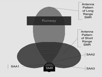
Figure 8 shows the coverage for one of the possible options of such SMR implementation using the suggested approach. A single SAA with a 42° antenna pattern is used for surveillance/imaging of the runway (a distant one: ~5 km away) while the relatively short-range (200–2000 m) area may be mapped using two other SAAs with a 90° antenna pattern each. After SAR/SAA processing the equivalent beam has an equivalent width of 0.14° provided by the 1.7 m synthesized aperture. Hence, we will have 300 resolution cells in azimuth for the runway surveillance radar, while for the short-range area radar we will have about 1350 cells in total for both antennas.
Coverage of different areas of an airport using long-range and short-range SMRs and three SAAs (SAA1, SAA2, and SAA3).

In general, application of the suggested approach gives much more flexibility in SMR design, unlike application of a single rotating antenna SMR. The latter is in wide use now, but requires an upgrade since it has significant limitations in parameters such as integration time, MTI capability, clutter suppression, etc. and requires high peak power and the application of a rotating antenna that complicates SMR construction and maintenance.
VI. CONCLUSIONS
Millimeter-wave SMR has been suggested, designed, and tested. Nevertheless, there is a need for SMR performance enhancement with low cost. We have suggested a novel concept for SMR design based upon application of NW-SAR that uses antennas of a new type: SAAs. Such an SMR has interesting potential capabilities for the design and development of compact, low-energy consumption and cost-effective SMR suitable, in particular, for monitoring the shadowed areas of airport layouts as well as for security-related applications. An attractive feature of the novel approach suggested consists in the ability to produce a series of SAR images at so high a rate that it may be displayed as a real-time video. This may be realized via fast motion of the antenna radiator across the aperture and online SAR processing. This will permit enhanced surveillance in novel advanced-surface movement guidance and control systems as well as in security systems for critical areas.
 Prof. Konstantin Lukin received his diploma in Radiophysics & Electronics from Kharkov State University (KhSU), Ukraine, in 1973. Since 1973 he is with the Institute for Radiophysics and Electronics, National Academy of Sciences of Ukraine, IRE NASU, Kharkov. He defended his Candidate of Science thesis in Moscow State University (MGU) in 1980 and his Doctor of Sciences dissertation in KhSU in 1989. He has been working, and has made appreciable contributions, in the fields of millimeter-wave vacuum electronics, random signal processing, dynamical chaos, and noise radar technology (NRT). His research interests are as follows: nonlinear dynamics and chaos in electronic systems; generation and processing of chaotic/noise waveforms and their applications. His main current activities lie in the field of NRT and its applications. He is Fellow of IEEE.
 Anatoly Mogyla was born on 19 May 1956. In 1978 he graduated from Kharkov Institute of Radioelectronics on a specialty of radio engineering. In 1998 he obtained a Ph.D. in physics and mathematics, and is Senior Research Fellow of the Laboratory for Nonlinear Dynamics of Electronic Systems of A. Usikov Institute for Radiophysics and Electronics NASU. His scientific interests include statistical radiophysics, radiolocation, radio engineering systems, and models and methods for signal processing.
 Pavlo Vyplavin was born in 1982 in Kharkiv, Ukraine. In 2004 he graduated from Kharkiv National University with an MS degree in radiophysics and electronics. Since 2004 he has been with the Laboratory of Nonlinear Dynamics of Electronic Systems of the Institute of Radiophysics and Electronics of NAS of Ukraine. In 2005 he took part in in-service training at the Joint Research Centre of the European Commission, Ispra, Italy, where he studied SAR imaging using noise radars.
His research interests are in the field of noise signal processing, noise radars, and SAR imaging.
 Gaspare Galati was with the company Selenia from 1970 till 1986, where he was involved in radar systems analysis and design. From March 1986 he has been associate professor (and full professor from November 1994) of radar theory and techniques at the Tor Vergata University of Rome, where he also teaches probability, statistics, and random processes. He is senior member of the IEEE, member of the IEE, and member of the AICT; within the AICT he is the chairman of the Remote Sensing, Navigation and Surveillance Group. He is the chairman of the SP and AES chapter of the IEEE. His main scientific interests are in radar, surveillance, navigation, and ATC/ASMGCS.
 Gabriele Pavan received the Electronics Engineering Degree (Laurea) from the Tor Vergata University of Rome in 1993. After the Laurea he continued research on radarmeteorology. In 2001 he received a Ph.D. in Environmental Engineering. From 2007 he has been a researcher at the Tor Vergata University, where he currently teaches Probability Theory and Signal Processing. His focus of research is on the observation of atmospheric phenomena by radar systems.