1 Introduction
Contactless objects draw their unique properties from their isolated nature. For instance, they can avert chemical and physical contamination (Duchemin, Lister & Lange Reference Duchemin, Lister and Lange2005), minimize thermal exchanges and prevent shocks and the resulting damage with their substrates. In addition, they have an unequalled mobility, which makes them glide with negligible friction compared to usual cases. In order to generate levitation, many techniques (Brandt Reference Brandt1989) relying on acoustics (Brandt Reference Brandt2001), magnetism (Souza et al. Reference Souza, Molina, Raphael, Ozawa, Stark, Levin, Bronk, Ananta, Mandelin and Georgescu2010), optics (Nagy & Neitzel Reference Nagy and Neitzel2008) or electrostatics (Sakata et al. Reference Sakata, Watanabe, Okada, Kumar, Paradis and Ishikawa2015) have been successfully developed. However, these techniques often imply complicated set-ups or restrictions regarding the objects that can be manipulated. Instead, air can simply be blown through porous media to induce levitation, such as done with air hockey tables (Lemaitre et al. Reference Lemaitre, Gervois, Peerhossaini, Bideau and Troadec1990; Hinch & Lemaitre Reference Hinch and Lemaitre1994). Airflow underneath an object can maintain it in mid-air under the action of inertial forces (Lemaitre et al. Reference Lemaitre, Gervois, Peerhossaini, Bideau and Troadec1990; Hinch & Lemaitre Reference Hinch and Lemaitre1994; Waltham, Bendall & Kotlicki Reference Waltham, Bendall and Kotlicki2003; Fitt, Kozyreff & Ockendon Reference Fitt, Kozyreff and Ockendon2004) and/or lubrication flows (Leidenfrost Reference Leidenfrost1966; Goldshtik, Khanin & Ligai Reference Goldshtik, Khanin and Ligai1986; Petit Reference Petit1986; Duchemin et al. Reference Duchemin, Lister and Lange2005; Wang Reference Wang2012; Bouwhuis et al. Reference Bouwhuis, Winkels, Peters, Brunet, van der Meer and Snoeijer2013; Snoeijer & van der Weele Reference Snoeijer and van der Weele2014). It is useful to understand and to optimize the key parameters needed for levitation, and to think of ways of simultaneously manipulating the objects in a controlled manner.
Here we propose to tackle both problems at once. Inspired by recent findings on the control of Leidenfrost drops by texturing the substrate on which they float (Linke et al. Reference Linke, Alemán, Melling, Taormina, Francis, Dow-Hygelund, Narayanan, Taylor and Stout2006; Hashmi et al. Reference Hashmi, Xu, Coder, Osborne, Spafford, Michael, Yu and Xu2012; Wells et al. Reference Wells, Ledesma-Aguilar, McHale and Sefiane2015; Soto et al. Reference Soto, Lagubeau, Clanet and Quéré2016), we study porous substrates (allowing take off) on top of which special structures are engraved (allowing manipulation). We first present a series of experiments showing the combination of levitation and propulsion, which we explain with scaling arguments. Then we develop an analytical model to capture the different observations, which leads us to propose other propelling situations.
2 Levitating hovercrafts
The potential hovercrafts are glass platelets with length
 $a$
, width
 $b<a$
and thickness
 $c$
. Their density being denoted as
 $\unicode[STIX]{x1D70C}$
(
 $\unicode[STIX]{x1D70C}=2130~\text{kg}~\text{m}^{-3}$
), the lamella mass
 $M$
is
 $\unicode[STIX]{x1D70C}abc$
, of the order of one gram in our experiments. The substrate is made of Plexiglas with thickness
 $H=2$
mm and pierced with a laser cutter (Epilog Helix 24) to obtain a square array of through holes with radius
 $r=90\pm 10~\unicode[STIX]{x03BC}\text{m}$
and spacing
 $p=400~\unicode[STIX]{x03BC}\text{m}$
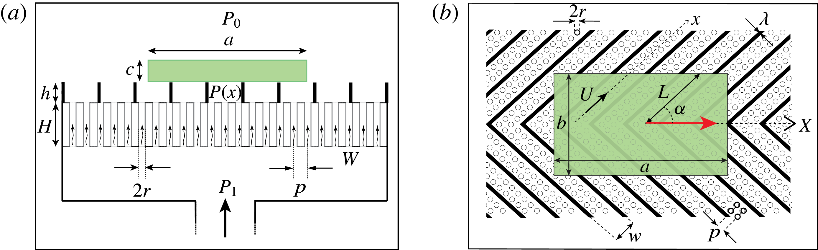
. This substrate closes the top of a Plexiglas box, in which we can inject air from below, as sketched in figure 1(a). A texture is finally etched on the porous material, consisting of rectangular channels with width
 $w=1$
mm and depth
 $h=180~\unicode[STIX]{x03BC}\text{m}$
separated by walls with thickness
 $\unicode[STIX]{x1D706}=0.3$
mm. These channels adopt a herringbone pattern (figure 1
b), an asymmetric design shown to induce directional motion of Leidenfrost drops (Soto et al.
Reference Soto, Lagubeau, Clanet and Quéré2016). We denote
 $\unicode[STIX]{x1D6FC}$
as the angle between the channel direction and the symmetry axis of the pattern. In order to have a controlled geometry, we experimentally impose
 $\unicode[STIX]{x1D6FC}>\arctan b/2a$
.
(a) Side view of the device. The top of a Plexiglas box is pierced by holes (radius
 $r\approx 100~\unicode[STIX]{x03BC}\text{m}$
, spacing
 $p=400~\unicode[STIX]{x03BC}\text{m}$
, length
 $H=2$
mm). Above this porous plate, we have channels with height
 $h=180~\unicode[STIX]{x03BC}\text{m}$
, on top of which we place a glass plate (in green) with length
 $a$
, width
 $b$
and thickness
 $c$
. Air injected in the box at a pressure
 $P_{1}>P_{0}$
escapes through pores at speed
 $W$
. The pressure in the channels, below the plate, is denoted as
 $P(x)$
. (b) Top view of the device. The channels form a herringbone pattern with angle
 $2\unicode[STIX]{x1D6FC}$
. Their width is
 $w=1$
mm and they are separated by walls with thickness
 $\unicode[STIX]{x1D706}=0.3$
mm. The air speed along a channel of axis
 $x$
and length
 $L=b/2\sin \unicode[STIX]{x1D6FC}$
is denoted as
 $U$
. As soon as airflow is strong enough to induce levitation, the plate starts moving in the
 $X$
-direction (red arrow).

An experiment first consists in adjusting the substrate horizontality, as checked with a spirit level with a precision of
 $0.1~\text{mm}~\text{m}^{-1}$
. Then air is injected in the box that acts as a reservoir whose pressure gradually increases from the atmospheric pressure
 $P_{0}$
to
 $P_{1}$
, at which the plate takes off. At this point, the plate does not contact the herringbone walls anymore and it skims just above the channels. Simultaneously, the plate is observed to move in the
 $X$
-direction, as indicated by the red arrow in figure 1(b). We record the motion with a video camera (uEye), from which we can access the position
 $X(t)$
. This function is parabolic and we deduce from the acceleration
 $\ddot{X}$
of the glider the propelling force
 $F=M\ddot{X}$
. To be more precise, we push several times the object (at typically
 $10~\text{cm}~\text{s}^{-1}$
) in the direction opposed to the propulsion (supplementary movie 1 available at https://doi.org/10.1017/jfm.2017.27), and monitor the deceleration, stop and acceleration of the plate, from which we extract
 $F$
. The dimensions
 $a$
,
 $b$
,
 $c$
set the levitation pressure
 $P_{1}$
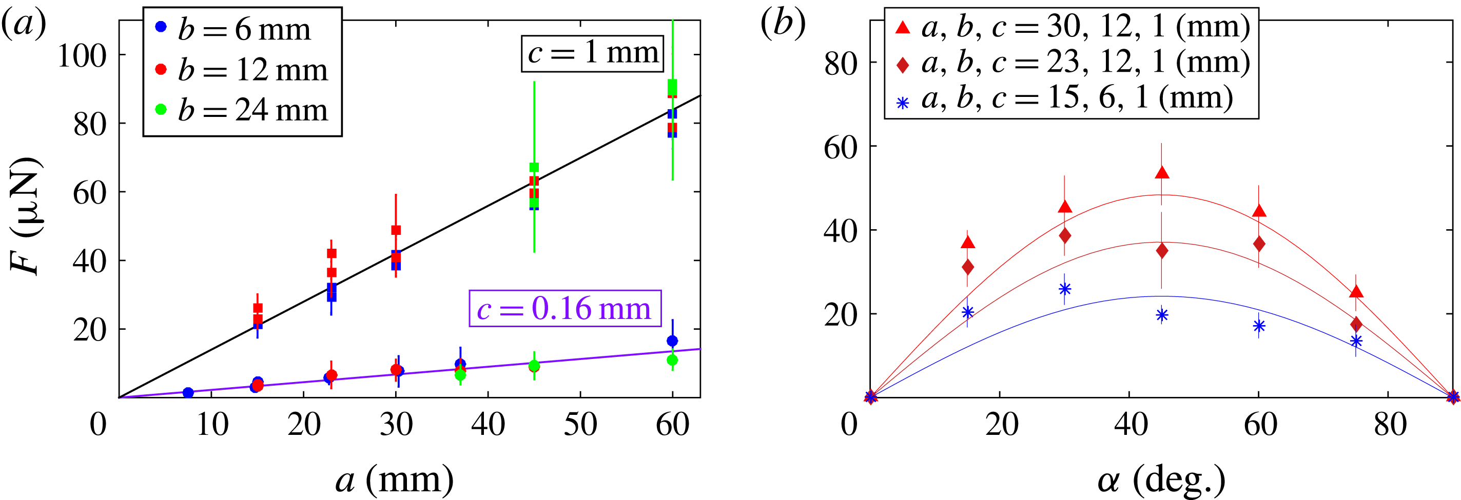
and thus impact the force propelling the object. We report in figure 2(a) how
 $F$
depends on
 $a$
,
 $b$
,
 $c$
for a herringbone texture with
 $h=180~\unicode[STIX]{x03BC}\text{m}$
and
 $\unicode[STIX]{x1D6FC}=45^{\circ }$
.
(a) Force
 $F$
propelling a plate on a herringbone, as a function of the plate length
 $a$
, for three widths:
 $b=6$
mm (blue data),
 $b=12$
mm (red data) and
 $b=24$
mm (green data), and two thicknesses:
 $c=0.16$
mm (circles) and
 $c=1$
mm (squares). Solid lines show the linear fit suggested by (2.1) and (3.8). (b) Propelling force
 $F$
as a function of the half-angle
 $\unicode[STIX]{x1D6FC}$
of the herringbone pattern. Each curve corresponds to a fixed lamella geometry with
 $[a,b,c]=[30,12,1]$
mm (triangles), [23, 12, 1] mm (diamonds) and [15, 6, 1] mm (asterisks). Solid lines show (3.8).
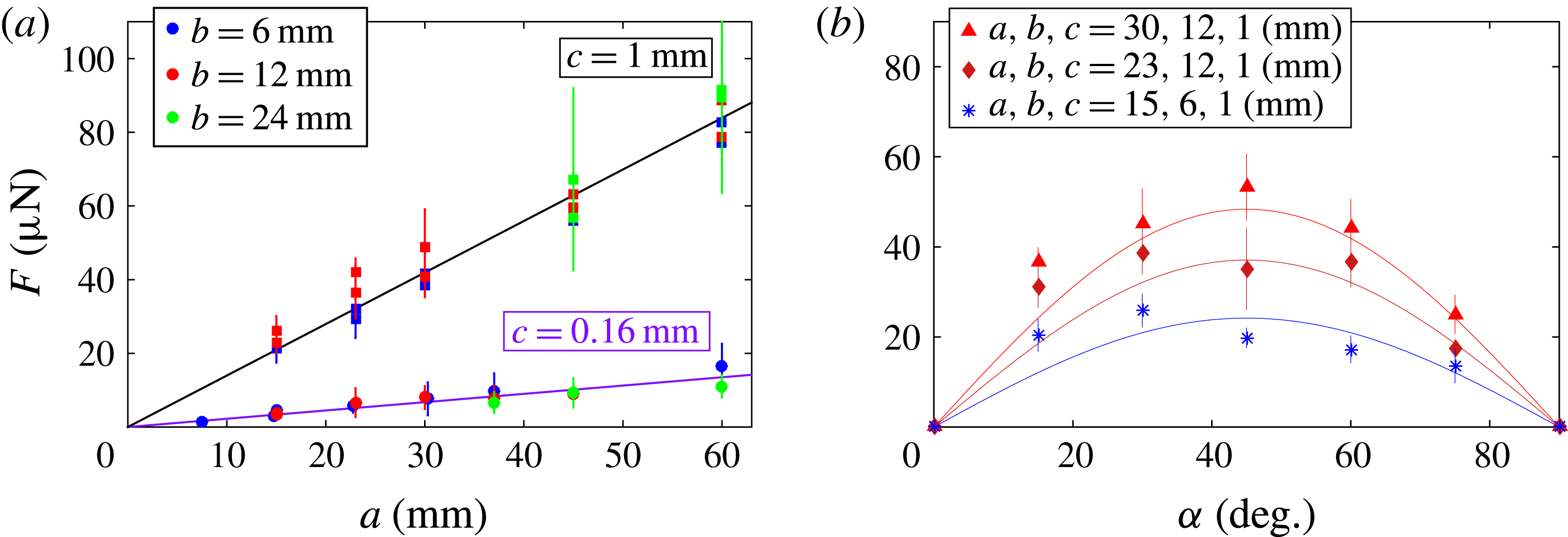
The force
 $F$
is found to span between 10 and
 $100~\unicode[STIX]{x03BC}\text{N}$
, that is, 1 % of the plate weight. In this frictionless situation,
 $F$
is large enough to propel the plate at typically
 $10~\text{cm}~\text{s}^{-1}$
after a few seconds. Propulsion depends on the plate geometry: it increases with both the length
 $a$
and thickness
 $c$
, but shows no obvious variation with width
 $b$
.
 $F(a)$
and
 $F(c)$
are both close to linear, as highlighted in figure 2(a) by the straight lines whose slope ratio is 6.25, close to 6.2, the ratio between the two thicknesses.
Plate motion arises from the presence of an asymmetric pattern, and we tested how
 $F$
is impacted by the characteristics of this texture. We can see in figure 2(b) that
 $F$
is not monotonic if plotted as a function of
 $\unicode[STIX]{x1D6FC}$
, the herringbone half-angle. It vanishes as
 $\unicode[STIX]{x1D6FC}$
reaches
 $0^{\circ }$
or
 $90^{\circ }$
and has its maximum around
 $\unicode[STIX]{x1D6FC}=45^{\circ }$
. This behaviour is valid for the three plates we tested, corresponding to dimensions
 $[a,b,c]$
in millimetres of [30, 12, 1] (triangles), [23, 12, 1] (diamonds) and [15, 6, 1] (asterisks). We recover here some of the properties observed for drops levitating on hot herringbones (Soto et al.
Reference Soto, Lagubeau, Clanet and Quéré2016): the propulsion direction is the same, and its efficiency is maximum for
 $\unicode[STIX]{x1D6FC}=45^{\circ }$
. However, the use of air-blown plates will allow us to discuss new aspects, and specifically to describe quantitatively the levitation and how to control these passive hovercrafts, for which we can freely choose the dimensions, unlike liquids.
Air coming out of the porous substrate has no other option than being channelled. Since objects move in the same direction as air, we assume that propulsion arises from the viscous drag generated by the directional airflow (Baier et al.
Reference Baier, Dupeux, Herbert, Hardt and Quéré2013). Denoting the air viscosity and characteristic speed as
 $\unicode[STIX]{x1D702}$
and
 $U$
(as defined in figure 1
b) and assuming
 $h\ll w$
, its flow will create in each channel a viscous stress
 $\unicode[STIX]{x1D70F}\sim \unicode[STIX]{x1D702}U/h$
acting on the glass slide over a surface area
 $ab\unicode[STIX]{x1D719}$
, where
 $\unicode[STIX]{x1D719}=w/(w+\unicode[STIX]{x1D706})$
is the portion of the area covered by channels. The resulting projected force along
 $X$
is
 $F\sim \unicode[STIX]{x1D702}Uab\unicode[STIX]{x1D719}\cos \unicode[STIX]{x1D6FC}/h$
, where
 $U$
is still unknown. It is obtained by balancing the viscous friction
 $\unicode[STIX]{x1D702}U/h^{2}$
in a channel by the gradient of pressure
 $\unicode[STIX]{x1D6FF}P/L$
responsible for the flow, denoting
 $L=b/2\sin \unicode[STIX]{x1D6FC}$
as the length of channels (see figure 1
b) and
 $\unicode[STIX]{x1D6FF}P$
as the overpressure inside them. Since the pressure beneath the plate has to support its weight, we assume that
 $\unicode[STIX]{x1D6FF}P$
scales as
 $\unicode[STIX]{x1D70C}gc$
, which yields the air velocity
 $U\sim 2\unicode[STIX]{x1D70C}gch^{2}\sin \unicode[STIX]{x1D6FC}/\unicode[STIX]{x1D702}b$
, and thus a scaling law for the force:
 $$\begin{eqnarray}F\sim \unicode[STIX]{x1D719}\unicode[STIX]{x1D70C}gach\sin 2\unicode[STIX]{x1D6FC}.\end{eqnarray}$$
Equation (2.1) predicts that
 $F$
linearly depends on both the plate length
 $a$
and thickness
 $c$
, as observed in figure 2(a). In addition, it predicts a maximum for
 $\unicode[STIX]{x1D6FC}=45^{\circ }$
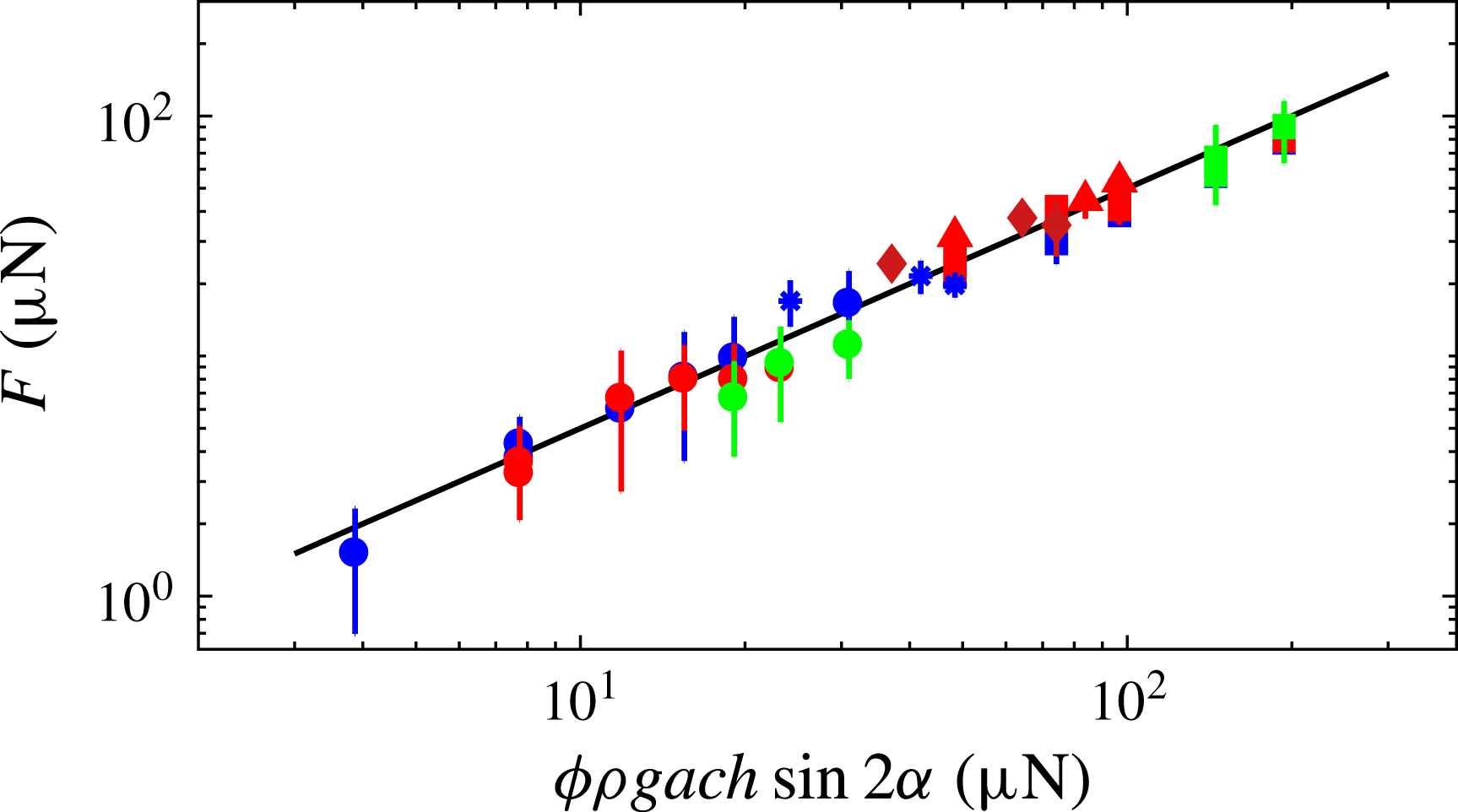
in agreement with figure 2(b). We compare in figure 3 the measured force to the one predicted by (2.1). All data collapse on a line of slope 1 with a numerical coefficient in (2.1) equal to
 $1/2$
, which we discuss further.
Measured propelling force for all the data of figure 2 (same symbol definition), as a function of the force provided by the scaling law (2.1). Each point is an average of 5–8 experiments. The equation of the solid line is
 $F=1/2\unicode[STIX]{x1D719}\unicode[STIX]{x1D70C}gach\sin 2\unicode[STIX]{x1D6FC}$
, that is, having the scaling of (2.1) and a numerical coefficient calculated in (3.8).

3 Model
Although scaling arguments capture the underlying physics, we can go further and take advantage of the well-defined geometry of the porous medium through which the air is injected at a mean speed
 $W$
. Our aim is to establish exact formulas for both the pressure needed for levitation and for the propelling force generated by the asymmetric pattern. We start by describing the airflow in the porous substrate, and express the Poiseuille law relating the flux per hole
 $Q=\unicode[STIX]{x03C0}r^{2}W$
to the pressure jump
 $P_{1}-P(x)$
between the box (experimentally controlled) and the channels (here
 $x$
is a coordinate parallel to the channel, as shown in figure 1
b). We have:
 $Q=(\unicode[STIX]{x03C0}r^{4}/8\unicode[STIX]{x1D702}H)(P_{1}-P(x))$
, where
 $H$
is the length of each pore (figure 1
a). Conservation of mass provides a second equation that links the injection speed
 $W$
and the velocity
 $U$
in the channels:
 $h\unicode[STIX]{x2202}U/\unicode[STIX]{x2202}x=Q/p^{2}$
. Hence we get:
 $$\begin{eqnarray}h\frac{\unicode[STIX]{x2202}U(x)}{\unicode[STIX]{x2202}x}=\frac{\unicode[STIX]{x03C0}r^{4}}{8\unicode[STIX]{x1D702}Hp^{2}}(P_{1}-P(x)).\end{eqnarray}$$
We can also recall the Poiseuille law in a channel:
 $$\begin{eqnarray}\frac{12\unicode[STIX]{x1D702}U(x)}{h^{2}}=-\frac{\unicode[STIX]{x2202}P}{\unicode[STIX]{x2202}x}.\end{eqnarray}$$
Combining (3.1) and (3.2), we obtain an equation of the form
 $\text{d}^{2}\unicode[STIX]{x1D713}(x)/\text{d}x^{2}=\unicode[STIX]{x1D713}(x)/\unicode[STIX]{x1D70E}^{2}$
for both functions
 $P_{1}-P(x)$
and
 $U(x)$
, where the characteristic distance
 $\unicode[STIX]{x1D70E}$
of the variation of the pressure
 $P$
and the speed
 $U$
is:
 $$\begin{eqnarray}\unicode[STIX]{x1D70E}=\sqrt{\frac{2Hp^{2}h^{3}}{3\unicode[STIX]{x03C0}r^{4}}}.\end{eqnarray}$$
The distance
 $\unicode[STIX]{x1D70E}$
depends on the geometrical characteristics of the porous substrate, namely
 $H$
,
 $p$
and
 $r$
, and on the height
 $h$
of the texture walls. All these parameters are fixed in our experiments, and we have
 $\unicode[STIX]{x1D70E}=3.0\pm 0.3$
mm.
We can integrate the equations for
 $P(x)$
and
 $U(x)$
, using as boundary conditions:
 $U(0)=0$
and
 $P(L)=P_{0}$
. We find:
 $U(x)=(P_{1}-P_{0})(h^{2}/12\unicode[STIX]{x1D702}\unicode[STIX]{x1D70E})((\sinh x/\unicode[STIX]{x1D70E})/(\cosh L/\unicode[STIX]{x1D70E}))$
and
 $P(x)-P_{0}=(P_{1}-P_{0})[1-((\cosh x/\unicode[STIX]{x1D70E})/(\cosh L/\unicode[STIX]{x1D70E}))]$
, where we still do not know the pressure
 $P_{1}$
needed to make the plate levitate just above the texture. Assuming that the corresponding force compensates the weight, we have at the scale of each channel:
 $\unicode[STIX]{x1D70C}gcL=\int _{0}^{L}[P(x)-P_{0}]\,\text{d}x$
, which yields:
 $$\begin{eqnarray}P_{1}-P_{0}=\unicode[STIX]{x1D70C}gc\,G\left(\frac{L}{\unicode[STIX]{x1D70E}}\right),\end{eqnarray}$$
where we introduced the function
 $G(x)=1/(1-(\tanh x)/x)$
. Equation (3.4) confirms that the levitation pressure is scaled by
 $\unicode[STIX]{x1D70C}gc$
, as assumed in the scaling analysis.
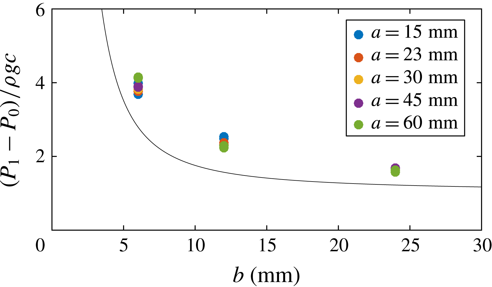
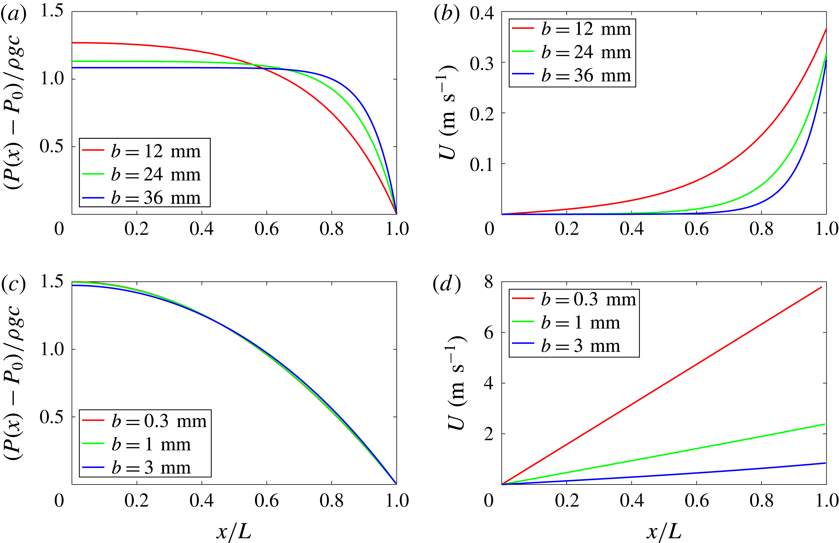
We show in figure 4 experimental measurements of this overpressure, as a function of the width
 $b$
of plates with length
 $a$
spanning from 15 to 60 mm and thickness
 $c=1$
mm. Drawn with a full line without an adjustable parameter, (3.4) is found to well describe the data. If we look back to figure 1(b) we observe that although most channels beneath the plate have the same length
 $L=b/(2\sin \unicode[STIX]{x1D6FC})$
, channels at the left and right edges of the plate become shorter, hence make a smaller contribution to overall lift. To compensate for this, we experimentally expect a higher reservoir pressure than the one predicted by (3.4), as observed in figure 4. In a similar way, for a given aspect ratio
 $b/a$
of the plate, decreasing angle
 $\unicode[STIX]{x1D6FC}$
will also accentuate this edge effect.
Levitation overpressure
 $P_{1}-P_{0}$
normalized by the weight per unit area
 $\unicode[STIX]{x1D70C}gc$
of the plate, as a function of the width
 $b$
of plates with thickness
 $c=1$
mm and length
 $a$
between 15 and 60 mm for a texture with angle
 $\unicode[STIX]{x1D6FC}=45^{\circ }$
. Equation (3.4) is drawn with a solid line.

The
 $G$
-function has two asymptotic regimes, which allows us to define ‘narrow’ and ‘wide’ plates: (i) For wide plates (
 $L>\unicode[STIX]{x1D70E}$
), the function
 $G(x)$
tends towards 1 and
 $P_{1}-P_{0}$
saturates at the ‘hydrostatic’ pressure
 $\unicode[STIX]{x1D70C}gc$
, as shown in figure 4 for large
 $b$
. (ii) In the narrow plate regime (
 $L<\unicode[STIX]{x1D70E}$
), the function
 $G(x)$
reduces to
 $3/x^{2}$
, leading to
 $P_{1}-P_{0}\approx 3\unicode[STIX]{x1D70C}gc\,\unicode[STIX]{x1D70E}^{2}/L^{2}$
, which diverges for
 $L\rightarrow 0$
, as seen in figure 4.
We can finally inject the levitation overpressure
 $P_{1}-P_{0}$
(3.4) in the expressions of
 $P(x)$
and
 $U(x)$
to obtain the exact profile solutions:
 $$\begin{eqnarray}\displaystyle & \displaystyle P(x)-P_{0}=\unicode[STIX]{x1D70C}gc\,G\left(\frac{L}{\unicode[STIX]{x1D70E}}\right)\left(1-\frac{\cosh {\displaystyle \frac{x}{\unicode[STIX]{x1D70E}}}}{\cosh {\displaystyle \frac{L}{\unicode[STIX]{x1D70E}}}}\right), & \displaystyle\end{eqnarray}$$
 $$\begin{eqnarray}\displaystyle & \displaystyle U(x)=\unicode[STIX]{x1D70C}gc\,\frac{h^{2}}{12\unicode[STIX]{x1D702}\unicode[STIX]{x1D70E}}G\left(\frac{L}{\unicode[STIX]{x1D70E}}\right)\frac{\sinh {\displaystyle \frac{x}{\unicode[STIX]{x1D70E}}}}{\cosh {\displaystyle \frac{L}{\unicode[STIX]{x1D70E}}}}. & \displaystyle\end{eqnarray}$$
Two different regimes can be observed regarding the length
 $L$
of the channel compared to
 $\unicode[STIX]{x1D70E}$
.
-
(i) In the wide plate regime (
 $L>\unicode[STIX]{x1D70E}$
, corresponding to most experiments since we have
$\unicode[STIX]{x1D70E}/L=0.11$
for
$b=36$
mm and
$\unicode[STIX]{x1D70E}/L=0.17$
for
$b=24$
mm), the latter expressions can be approached by: (3.6a,b )Pressure in the channel drops exponentially from
$$\begin{eqnarray}P(x)-P_{0}\approx \unicode[STIX]{x1D70C}gc\,(1-\text{e}^{(x-L)/\unicode[STIX]{x1D70E}}),\quad U(x)\approx \unicode[STIX]{x1D70C}gc\,\frac{h^{2}}{12\unicode[STIX]{x1D702}\unicode[STIX]{x1D70E}}(\text{e}^{(x-L)/\unicode[STIX]{x1D70E}}).\end{eqnarray}$$
$\unicode[STIX]{x1D70C}gc$
to atmospheric pressure in a narrow region fixed by
$\unicode[STIX]{x1D70E}$
as shown in figure 5(a). The uniformity of pressure elsewhere explains the absence of airflow in most of the channel, as seen in figure 5(b). Since airflow is confined in a region of order
$\unicode[STIX]{x1D70E}$
close to the plate edge, drag appears to be localized in this region.
-
(ii) In the narrow plate regime (
$L<\unicode[STIX]{x1D70E}$
), a Taylor expansion leads to: (3.7a,b )The variations of
$$\begin{eqnarray}P(x)-P_{0}\approx \frac{3}{2}\,\unicode[STIX]{x1D70C}gc\left(1-\frac{x^{2}}{L^{2}}\right),\quad U(x)\approx \unicode[STIX]{x1D70C}gc\,\frac{h^{2}}{4\unicode[STIX]{x1D702}L^{2}}x.\end{eqnarray}$$
$P$
and
$U$
invade the channel as shown in figures 5(c) and 5(d), so that a larger pressure is needed to sustain the plate and drag is exerted over a wider distance. As shown by the large difference of scale in vertical axis between figures 5(b) and 5(d), corresponding air velocities can then become large enough to make us leave the regime of small Reynolds number assumed and checked in § 4.


(a,c) Calculated pressure
 $P(x)$
(3.5a
) and (b,d) speed
 $U(x)$
(3.5b
), as a function of the position
 $x$
in a channel of length
 $L=b/2\sin \unicode[STIX]{x1D6FC}$
and angle
 $\unicode[STIX]{x1D6FC}=45^{\circ }$
, for plates of various widths
 $b$
, thickness
 $c=0.16$
mm and length
 $a=60$
mm. (a,b) Correspond to the wide plate regime (
 $L>\unicode[STIX]{x1D70E}$
) where the characteristic distance of variation of
 $P$
and
 $U$
happens close to the exit of the channel with an exponential behaviour as shown by (3.6a,b
). (c,d) Correspond to the narrow plate regime (
 $L<\unicode[STIX]{x1D70E}$
) where channel is smaller than the characteristic decay distance
 $\unicode[STIX]{x1D70E}$
and variations invade the whole channel. As a result, we have a parabolic expression for the pressure (which is maximum for
 $x=0$
with a value
 $(3/2)\unicode[STIX]{x1D70C}gc$
) and a linear profile for speed, as described by (3.7a,b
).

We can use the analytical solutions for the speed and pressure to calculate the viscous force exerted by the airflow on the plate. The local stress being
 $\unicode[STIX]{x1D70F}=6\unicode[STIX]{x1D702}U/h$
and using (3.2), we find per channel:
 $F_{i}=\int _{0}^{L}\int _{0}^{w}\unicode[STIX]{x1D70F}\,\text{d}x\,\text{d}y=(hw/2)[P(0)-P_{0}]$
. Previous solution for
 $P(x)$
yields:
 $P(0)-P_{0}=\unicode[STIX]{x1D70C}gc\;S(L/\unicode[STIX]{x1D70E})$
where
 $S(x)=G(x)\,(1-1/\cosh x)$
. Considering the number
 $N=2a\sin \unicode[STIX]{x1D6FC}/(w+\unicode[STIX]{x1D706})$
of active channels (channels that are open on both ends do not contribute to propulsion as seen on the left part of the plate in figure 1
b) and projecting the force along the motion, we get
 $F=(1/2)\unicode[STIX]{x1D719}\unicode[STIX]{x1D70C}gcah\sin 2\unicode[STIX]{x1D6FC}\;S(L/\unicode[STIX]{x1D70E})$
. The function
 $S$
is monotonically decreasing from
 $3/2$
to 1 so that
 $P(0)-P_{0}$
is always bounded between
 $\unicode[STIX]{x1D70C}gc$
and
 $(3/2)\unicode[STIX]{x1D70C}gc$
(as seen in figures 5
a and 5
c). Since experiments are performed in the wide plate regime (
 $L>\unicode[STIX]{x1D70E}$
), we have
 $S(L/\unicode[STIX]{x1D70E})\approx 1$
;
 $P(0)-P_{0}$
reduces to
 $\unicode[STIX]{x1D70C}gc$
, and
 $F$
becomes:
 $$\begin{eqnarray}F={\textstyle \frac{1}{2}}\unicode[STIX]{x1D719}\unicode[STIX]{x1D70C}gcah\sin 2\unicode[STIX]{x1D6FC}.\end{eqnarray}$$
Equation (3.8) confirms the scaling found in (2.1) for which it provides a numerical coefficient of
 $1/2$
, in excellent agreement with the data in figure 3. We can deduce from (3.8) the maximum climbable slope
 $\unicode[STIX]{x1D703}_{max}$
on solids tilted by an angle
 $\unicode[STIX]{x1D703}$
: the projection of the plate weight along the substrate being
 $\unicode[STIX]{x1D70C}abcg\sin \unicode[STIX]{x1D703}$
, we obtain with
 $\unicode[STIX]{x1D6FC}=45^{\circ }$
 $\unicode[STIX]{x1D703}_{max}\approx h/2b$
, that is, approximately 1.5 %. We can see in the supplementary movie 2 a plate with
 $b=6$
mm on a texture having
 $h=0.18$
mm moving against a slope of 1.2 %, a value slightly smaller than
 $\unicode[STIX]{x1D703}_{max}$
.
4 Reynolds number
In all our experiments, the crenel depth
 $h$
is fixed and constant. Increasing the platelet thickness
 $c$
(or analogously the crenel depth
 $h$
) results in an increase of the needed injection speed
 $W$
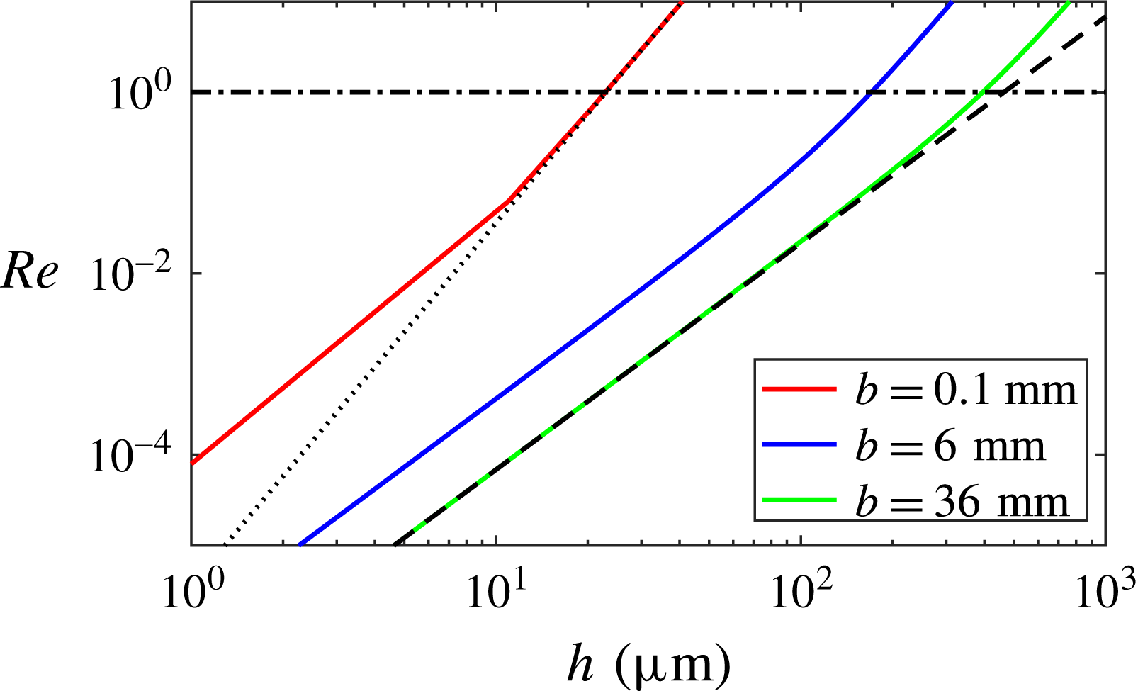
. Eventually, there will be a point when airflow speed will no longer allow us to assume low Reynolds regime. Since speed
 $U$
is maximal at
 $x=L$
and the Reynolds number expression writes
 $\unicode[STIX]{x1D70C}_{a}Uh^{2}/\unicode[STIX]{x1D702}L$
(where
 $\unicode[STIX]{x1D70C}_{a}$
denotes air density), the maximal Reynolds number is:
 $$\begin{eqnarray}Re=\frac{\unicode[STIX]{x1D70C}_{a}\unicode[STIX]{x1D70C}gch^{4}}{12\unicode[STIX]{x1D702}^{2}L^{2}}K\left(\frac{L}{\unicode[STIX]{x1D70E}}\right),\end{eqnarray}$$
where the function
 $K$
is defined as
 $K(L/\unicode[STIX]{x1D70E})=(L/\unicode[STIX]{x1D70E})G(L/\unicode[STIX]{x1D70E})\tanh (L/\unicode[STIX]{x1D70E})$
. Two asymptotic regimes can be observed.
-
(i) For ‘narrow’ plates
$b\ll \unicode[STIX]{x1D70E}(\propto h^{3/2})$
we have
$K(L/\unicode[STIX]{x1D70E})\sim 3$
, leading to a Reynolds number proportional to
$h^{4}$
(dotted line in figure 6): (4.2)
$$\begin{eqnarray}Re\propto h^{4}.\end{eqnarray}$$
-
(ii) For ‘wide’ plates
$b\gg \unicode[STIX]{x1D70E}(\propto h^{3/2})$
,
$K(L/\unicode[STIX]{x1D70E})$
reduces to
$L/\unicode[STIX]{x1D70E}$
, and we have (dashed line in figure 6): (4.3)
$$\begin{eqnarray}Re\propto h^{5/2}.\end{eqnarray}$$


Reynolds number
 $Re$
as a function of channel depth
 $h$
as predicted by (4.1). Thickness is fixed to
 $c=1$
mm (corresponding to our thickest plates, hence highest experimental
 $Re$
), plate width
 $b\in [0.1,6,36]$
mm (as indicated with colours) and angle
 $\unicode[STIX]{x1D6FC}=45^{\circ }$
. The dashed black line shows asymptotic behaviour
 $h^{5/2}$
((4.3) for ‘wide plates’, also corresponding to shallow crenels). The dotted black line shows asymptotic behaviour
 $h^{4}$
((4.2) for ‘narrow’ plates or deep crenels).
 $Re=1$
is shown with a dash-dot black line to visualize the range of validity of our assumption, represented by the region beneath it.

We show (4.1) in figure 6 as a function of the channel depth
 $h$
for different widths
 $b$
and a thickness fixed to our highest value
 $c=1$
mm. In our experiments, the worst scenario (where the Reynolds number is highest) corresponds to the thickest and most narrow plate (
 $c=1$
mm and
 $b=6$
mm, blue curve in figure 6), for which we indeed have
 $Re\leqslant 1$
(given that we have fixed
 $h=180~\unicode[STIX]{x03BC}\text{m}$
). All other plates have smaller Reynolds number (
 $Re\leqslant 0.3$
), agreeing with our viscous scenario. Since we have
 $\unicode[STIX]{x1D70E}\propto h^{3/2}$
, we can observe for each curve a transition from ‘wide’ plate to ‘narrow’ plate regime, seen in figure 6 by a change in slope.
5 Other propelling designs
Our findings can be exploited to create new propelling designs. We qualitatively discuss two of them.
5.1 The truncated herringbone
In the wide plate regime, viscous drag only acts over the last few millimetres of the channels, by a distance
 ${\sim}\unicode[STIX]{x1D70E}$
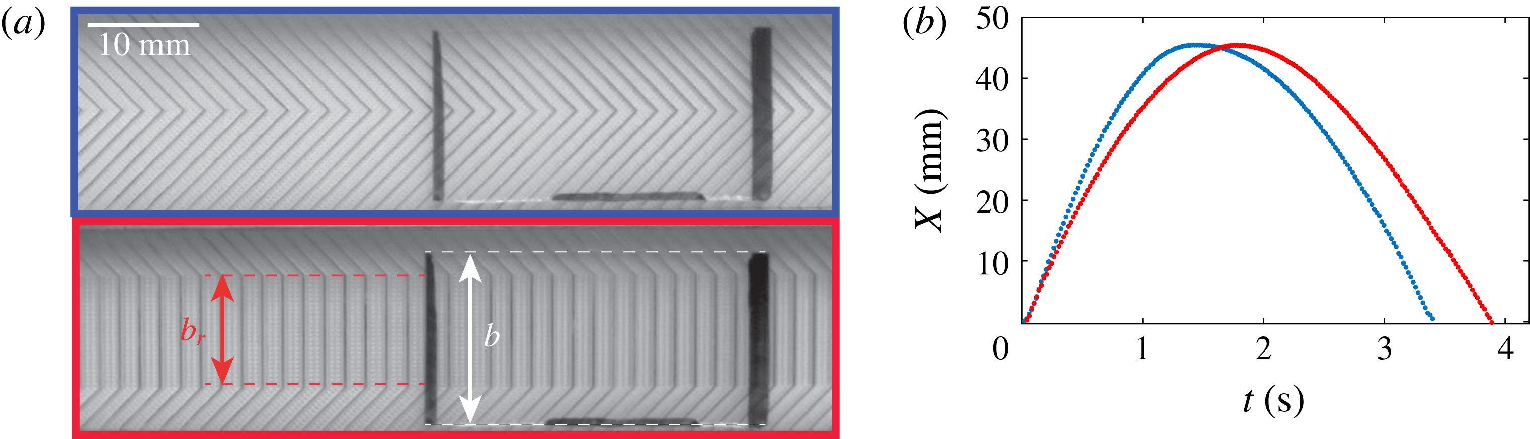
at the plate edges (3.3). Hence the central part of a herringbone should not play a major role in plate propulsion, but mainly contributes to levitation. We tested this result by comparing the efficiency of regular and truncated herringbones (figure 7
a), where the latter design has a central straight section of length
 $b_{T}$
(
 $b_{T}=10$
mm) perpendicular to the motion (supplementary movie 3). We compare in figure 7(b) the trajectories on both textures, for a slide (
 $a=30$
mm,
 $b=15$
mm,
 $c=1$
mm) launched at
 $V\approx 5~\text{cm}~\text{s}^{-1}$
against the propelling direction. The drag force accelerates the plate, resulting in a trajectory close to a parabola (friction is negligible at this scale). Trajectories on both textures are similar, indicating that the two devices have comparable propelling abilities despite marked geometrical differences.
We deduce from the trajectories
 $F_{T}=30\pm 5~\unicode[STIX]{x03BC}\text{N}$
for the truncated herringbone and
 $F=45\pm 5~\unicode[STIX]{x03BC}\text{N}$
for the regular one. We can adapt the reasoning done for a regular herringbone (3.8) to obtain the corresponding truncated version. The local stress being
 $\unicode[STIX]{x1D70F}=6\unicode[STIX]{x1D702}U/h$
and using (3.2), we find that the contribution to the total force between two points
 $x_{1}$
and
 $x_{2}$
along the channel is
 $F_{x_{1,2}}=\int _{x_{1}}^{x_{2}}\int _{0}^{w}\unicode[STIX]{x1D70F}\,\text{d}x\,\text{d}y=hw/2[P(x_{1})-P(x_{2})]$
. For the truncated herringbone the stresses have an effective projection to propulsion only between
 $x_{1}=b_{T}/2$
and the final length of the channel
 $x_{2}=b_{T}/2+(b-b_{T})/(2\sin \unicode[STIX]{x1D6FC})$
(instead of
 $x_{1}=0$
and
 $x_{2}=b/2\sin \unicode[STIX]{x1D6FC}$
in the regular case). Hence the ratio
 $F_{T}/F$
will be equal to
 $(P(b_{T})-P_{0})/(P(0)-P_{0})$
. Using (3.5b
), we get
 $F_{T}/F=0.8$
, very close to the experimental value of
 $0.7\pm 0.1$
, confirming that viscous drag is mainly concentrated along the slide sides.
Two designs entraining a glass plate (
 $a=30$
mm,
 $b=15$
mm,
 $c=1$
mm) with mass
 $M=1$
g. (a) Top and bottom textures are regular and truncated herringbones, with same
 $\unicode[STIX]{x1D6FC}$
and a central straight section in the latter case with length
 $b_{T}=10$
mm. (b) Plate trajectory for these two textures. The plate is initially pushed against the propelling direction, so that it accelerates in the opposite direction: blue and red data respectively correspond to regular and truncated herringbones.

5.2 The rotating mill
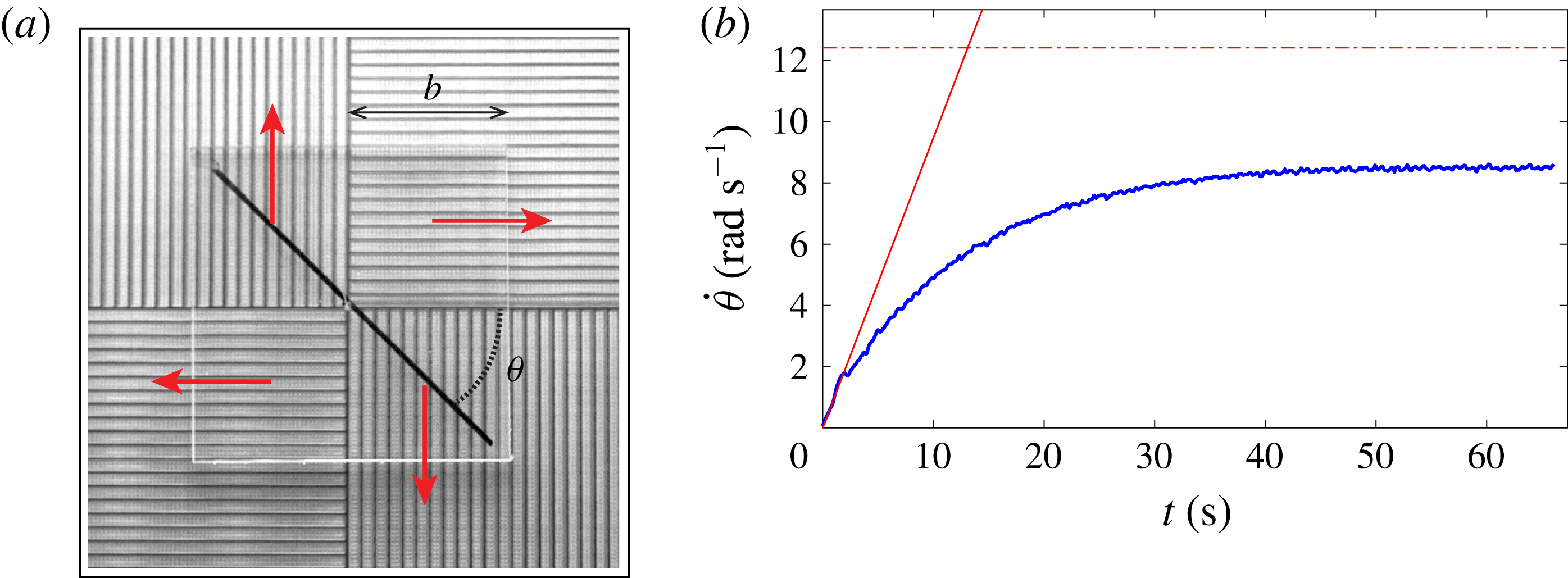
We discussed up to now translational motion. In term of manipulation, it is often necessary to achieve rotation. For this purpose, we developed a texture made of four sections with parallel grooves whose direction rotates by
 $90^{\circ }$
in each quadrant (figure 8
a). A plate of side
 $2b$
and thickness
 $c$
is centred with a thin needle on this windmill texture, so that viscous drag acts on the plate in the direction of the arrow in figure 8(a), which leads to rotation, as seen in figure 8(b) and in the supplementary movie 4.
(a) Top view of a windmill texture consisting of four quadrants with parallel grooves (
 $w=1$
mm,
 $\unicode[STIX]{x1D706}=0.3$
mm,
 $h=180~\unicode[STIX]{x03BC}\text{m}$
). Glass fibre, acting as a central axis, keeps centred a Plexiglas plate with side
 $2b$
levitating above the texture. Red arrows show viscous drag in each quadrant resulting in rotation, quantified by the angle
 $\unicode[STIX]{x1D703}$
. (b) Angular velocity
 $\dot{\unicode[STIX]{x1D703}}$
as a function of time
 $t$
, for a plate with
 $c=1$
mm and
 $b=20$
mm. The slope of solid red line is
 $1.00\pm 0.05~\text{rad}~\text{s}^{-2}$
corresponding to the initial acceleration
 $\ddot{\unicode[STIX]{x1D703}}_{0}$
. Horizontal red dashed line corresponds to maximal rotation speed
 $\dot{\unicode[STIX]{x1D703}}_{\infty }$
without friction.

The angular velocity starts from 0, increases for approximately 30 s, until it reaches a plateau at
 $\dot{\unicode[STIX]{x1D703}}_{\infty }=8.5\pm 0.1~\text{rad}~\text{s}^{-1}$
, corresponding to a linear velocity
 $\dot{\unicode[STIX]{x1D703}}_{\infty }b$
of approximately
 $17~\text{cm}~\text{s}^{-1}$
. Figure 8(b) highlights the existence of a terminal regime for plate propulsion.
Using the previous expression of entrainment force for a single wide channel, we can write the corresponding torque
 $M_{i}$
acting on the plate and scaling as
 $\unicode[STIX]{x1D70C}gchwb\sin \unicode[STIX]{x1D6FC}$
, where
 $\unicode[STIX]{x1D6FC}$
is the angle between the channel direction and the edge of the plate; this angle spans between
 $0^{\circ }$
and
 $45^{\circ }$
for a square plate. Reducing the contribution of
 $\sin \unicode[STIX]{x1D6FC}$
to its average value, the total torque
 $M$
experienced by the plate scales as
 $\unicode[STIX]{x1D719}((1-\cos \unicode[STIX]{x03C0}/4)/(\unicode[STIX]{x03C0}/4))\unicode[STIX]{x1D70C}gchb^{2}$
. Since the moment of inertia for a square plate varies as
 $\unicode[STIX]{x1D70C}cb^{4}$
, Newton’s law provides an initial angular acceleration of the plate scaling as
 $\ddot{\unicode[STIX]{x1D703}}_{0}\sim g(h/b^{2})\unicode[STIX]{x1D719}((1-\cos \unicode[STIX]{x03C0}/4)/(\unicode[STIX]{x03C0}/4))$
. This simple argument allows us to predict an initial acceleration of
 $1.2~\text{rad}~\text{s}^{-2}$
, a value close to
 $1.00\pm 0.05~\text{rad}~\text{s}^{-2}$
deduced from figure 8(b). Once the plate starts accelerating two new mechanisms leading to the saturation regime seen in figure 8(b) have to be taken into account.
-
(i) Drag is generated due to the shear between the top plate (initially at rest) and the underlying flow. Once the plate starts accelerating, the shear will decrease until it drops to zero when the plate speed
$b\dot{\unicode[STIX]{x1D703}}$
and the projection of the speed flow in the same direction
$U\sin \unicode[STIX]{x1D6FC}$
become equal. Averaging the role of
$\sin \unicode[STIX]{x1D6FC}$
between 0 and
$\unicode[STIX]{x03C0}/4$
as previously done, we can predict that the maximal final rotation speed
$\dot{\unicode[STIX]{x1D703}}_{\infty }$
is
$U(L)/b((1-\cos \unicode[STIX]{x03C0}/4)/(\unicode[STIX]{x03C0}/4))$
. Using (3.5b
) (or its approximate version (3.6b
)) we obtain
$\dot{\unicode[STIX]{x1D703}}_{\infty }\approx 12~\text{rad}~\text{s}^{-1}$
. -
(ii) Due to friction, we can see in figure 8(b) that saturation is reached around
$8~\text{rad}~\text{s}^{-1}$
, a value below the expected
$\dot{\unicode[STIX]{x1D703}}_{\infty }$
of
$12~\text{rad}~\text{s}^{-1}$
. Indeed, if we take the simple case of a Couette-style plate rotating on a resting surface at height
$h$
, the torque associated with viscous shear will scale as
$\unicode[STIX]{x1D702}\dot{\unicode[STIX]{x1D703}}/hb^{4}$
. Using again Newton’s law, we can deduce a slow down over a time scale
$\unicode[STIX]{x1D70F}\sim (\unicode[STIX]{x1D70C}ch)/\unicode[STIX]{x1D702}$
, typically 10 s for a plate similar to the one used in our experiments.





6 Concluding remarks
Future work might follow various directions. (i) It would be interesting to see what happens if water is blown instead of air, which would allow us to propel solids immersed in water. (ii) Our model was developed in the limit of small Reynolds numbers. Heavier plates or deeper grooves would lead to a higher gas velocity, and thus to Reynolds numbers possibly larger than unity. It would be useful to understand how inertial effects impact our findings. (iii) A more versatile device would carry its own propelling principle: a first step in this direction would be to study what happens if we transfer the propelling texture to the base of the levitating object itself, and make it levitate on a flat porous substrate. (iv) The study of the friction experienced by a plate on a crenelated texture would set the first stone to completely model the saturation of the velocity, in particular for the case of the rotating mill.
Acknowledgement
We thank the referees for very interesting remarks about our manuscript.
Supplementary movies
Supplementary movies are available at https://doi.org/10.1017/jfm.2017.27.