I. INTRODUCTION
The need for an efficient utilization of the frequency spectrum and an increasing number of RF circuits operating in the same system, as well as the reduction of volume and weight of communication systems, can be satisfied by simplifying the system architecture and by reducing the bulk of single devices. Dual-band and multi-band filters are key elements to simplify the system architecture by replacing multiplexed filters, which utilize two separate single band filters and two combining networks at the input and output [Reference Holme1, Reference Zhang and Mansour2]. Due to this, the attention to multiple band filters is growing in the last years and several papers are devoted to the study and implementation of these types of devices [Reference Macchiarella and Tamiazzo3, Reference Bila, Cameron, Lenoir, Lunot and Seyfert4] with different synthesis techniques and in different technologies. In order to reduce the bulk of single devices the use of dual mode filters configuration significantly decreases the dimensions of the filters since it allows for halving the number of cavities. The dual-mode concept consists of using a pair of resonant modes within a single physical cavity; without any perturbation the two dominant degenerate modes have the same resonant frequencies and different methods are used in order to split these frequencies, for example as by meaning of a square corner cut rectangular waveguide [Reference Liang, Zaki and Atia5]. In the case of low loss requirements, the filter technology which offers the higher performance is surely the waveguide technology. Anyway, as well-known, its main drawback is the overall size and mass of the filter devices. For these reasons in order to minimize their volume and mass, dual-mode cavities, exploiting multiple resonant modes within a single physical cavity, have been employed [Reference Snyder6]. In the filter concepts based on transverse magnetic (TM) dual-mode cavities presented in [Reference Bastioli, Tomassoni and Sorrentino7, Reference Tomassoni, Bastioli and Sorrentino8], the size compactness of the structure does not compromise the performance which remains similar to that of standard waveguide filters, or even better thanks to the possibility to realize Nth order filtering function with N transmission zeros (TZs).
The combination of the two concepts has already been presented in [Reference Nocella, Cacciamani, Tomassoni, Sorrentino and Pelliccia9] with one configuration of the TZs; here the concept has been extended to another configuration: to validate the proposed concept, two three-cavity TM dual-band filters (i.e. three transmission poles for each passband) with six TZs have been designed and manufactured. Furthermore, a study over temperature from 20 °C up to 80 °C has been carried out.
II. TM CAVITY WITH DUAL-BAND RESPONSE
TM dual-mode cavities have been used in order to obtain different zero positioning in two dual band filters. The approach exploits TM120 and TM210 modes as resonant modes, determined by the cavity dimensions w and h, as defined in equation (1). Also a set of non-resonating modes (modes that resonate far away from the filter pass-band [Reference Tomassoni, Bastioli and Sorrentino8]) are involved in the cavity and can provide a cross-path between input and output in each cavity and the main contribution to such input-output coupling is given by the TM11 mode. The H-field distributions of resonant TM120 and TM210 modes and the non-resonating TM11 mode are depicted in Fig. 1. As is evident in equation (1), the length of the cavity does not significantly affect the two resonant mode frequencies, thus it can be minimized, and this allows for very short waveguide filters [Reference Tomassoni, Bastioli and Sorrentino8, Reference Nocella, Cacciamani, Tomassoni, Sorrentino and Pelliccia9].
 $$f_{120} = \displaystyle{c \over {2\pi}} \sqrt {\left( {\displaystyle{\pi \over w}} \right)^2 + \left( {\displaystyle{{2\pi} \over h}} \right)^2} ;\quad f_{210} = \displaystyle{c \over {2\pi}} \sqrt {\left( {\displaystyle{{2\pi} \over w}} \right)^2 \left( {\displaystyle{\pi \over h}} \right)^2}. $$
H-field distributions along the cavity cross-section: the non-resonating mode TM11; the two resonant modes, i.e. TM120 and TM210.

The advantage of this approach is that multiple cavity filters can be obtained by using generalized TM dual-mode cavities as basic building blocks, simultaneously exploiting the maximum number of finite frequency TZs. By cascading the different blocks properly designed it is possible to guarantee that all of the TZs generated by each block will still appear in the overall filter response obtaining a dual band Nth-order filters with N TZs.
In the following, two design examples of three-cavity filters will be presented.
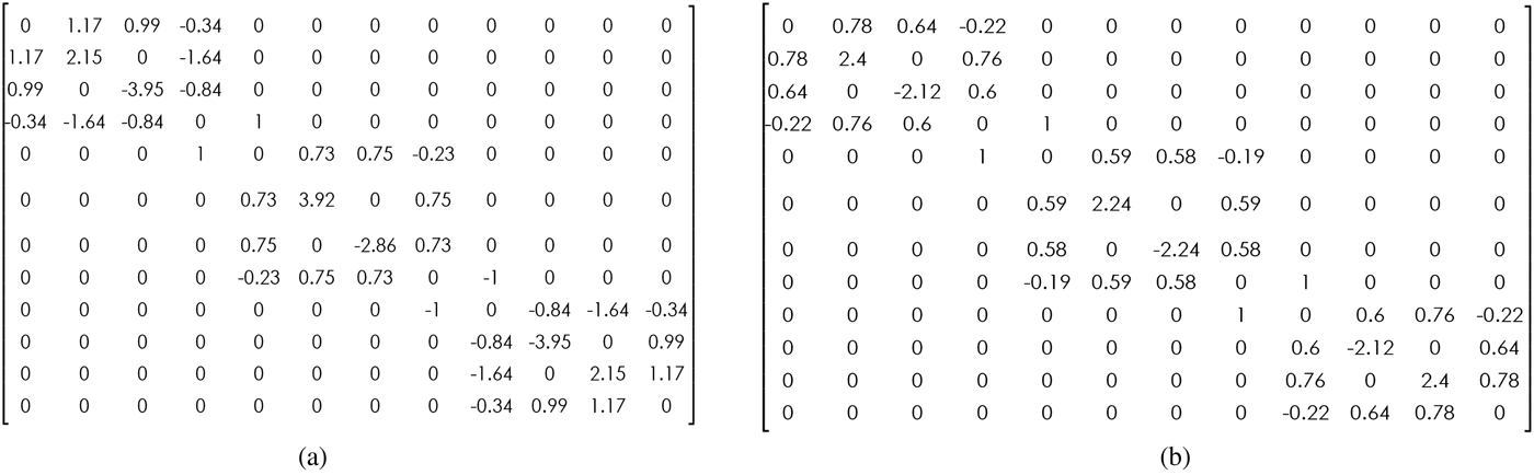
Filters have been designed by using the relevant coupling matrices shown in Fig. 2. Each coupling matrix is constituted by three sub-matrices, corresponding to the three doublets composing the 6-pole filter. Each sub matrix can be obtained by means of a single cavity conveniently dimensioned and excited. Note that the lower band is due to the TM120 mode of each cavity, while the higher band is obtained exploiting the TM210 mode. By setting the cavity dimensions, i.e. w and h, very different one to each other, the resonant frequencies of the TM120 and TM210 modes are opportunely split.
Coupling matrices of the designed filters.
To design the first complete 6-poles dual band filter, called “(1-3-2) TZs”, three generalized TM dual-mode cavities have been designed: the first and the third correspond to the coupling matrix of Fig. 3(b), that allows for one TZ above the second band pass and one TZ between the two bands, while the second corresponds to the coupling matrix in Fig. 3(a), that allows for one TZ between the two bands and one TZ below the first band pass. These sub matrices correspond to the topology configurations and S-parameters shown in Figs 3(c) and 3(d), respectively. Starting from sub-matrices of Fig. 2(a), each doublet has been individually designed and then the three cavities have been cascaded, initially through a relatively thick slot, representing a non-resonating node, similar to the one described in [Reference Tomassoni, Bastioli and Sorrentino8]. Then a fine optimization has been performed considering thin slots (1 mm), thus yielding a very compact structure. Notice that, in order to obtain a symmetric structure, cavities corresponding to first and third sub-matrices are equal and generate zeros in the same position, thus resulting in double zeros. When the slots become thin, they no longer represent the non-resonating node and some spurious coupling phenomena occur within the filter. As a result, multiple cross couplings arise, and the cavities are no longer independent. As a consequence, TZs are not fully individually controlled by the corresponding cavity, the double TZs are separated and they are slightly moved.
Building blocks for dual-band filters and relevant coupling matrix.
Starting from the individual design of three cavities each having one TZ below the first band pass and one TZ between the two bands, the same design procedure described in the previous example has been carried out for the optimization of the second 6-poles dual band filter, called “(3-3-0) TZs” in which TZs are evenly located below each pass-band.
III. RESULTS
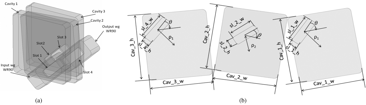
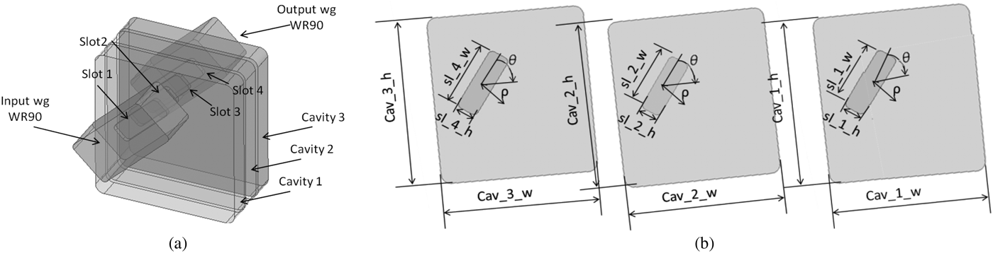
In order to prove the feasibility of the proposed approach, two three-cavity dual-band filters in X-band have been designed in high frequency structural simulator (HFSS) and manufactured. Each filter has been optimized in order to achieve three transmission poles per each pass-band and six TZs in total. The (1-3-2) TZs filter has three of the six TZs between the two pass-bands, another one below the lower pass-band and the remaining two TZs are above the higher pass-band; instead, the second filter has three TZs below the lower pass-band and three between the two pass-bands. The three-dimensional models for the (1-3-2) TZs filter and (3-3-0) TZs filter are shown in Figs 4 and 5, respectively. Regarding the (1-3-2) TZs filter the first band is centered at 9.3 GHz with 3.4% fractional bandwidth (FBW), while the second band is centered at 9.95 GHz with 2.2% FBW; the (3-3-0) TZs filter has the first band centered at 9.3 GHz with 1.3% FBW, while the second band is centered at 10.06 GHz with 1.3% FBW. As shown in Fig. 4 and in Fig. 5, each filter is composed of three cavities and four slots, the I/O waveguide are standard WR90; the corners of each cavity and slot have been rounded for manufacturing reasons, the milling radius is 2 and 1 mm, respectively.
Structure of the optimized 6-poles (1-3-2) TZs filter.
Structure of the optimized 6-poles (3-3-0) TZs filter.
Referring to Fig. 4(b), taking into account that slot 2 and slot 3 in Fig. 4(a) are equal, the dimensions in mm of the (3-3-0) TZs filter are: Cav_1_h = 35.95 = Cav_3_h, Cav_1_w = 32.25 = Cav_3_w, Cav_2_h = 35.83, Cav_2_w = 32.51, sl_1_h = 4.695 = sl_4_h, sl_1_w = 14.59 = sl_3_w, sl_2_h = 4.635, sl_2_w = 13.33, ρ 1 = 13, ρ 2 = 8, θ = 0°. The second cavity is rotated at 4° with respect to the first and the third.
In Fig. 5 the structure of the (3-3-0) TZs filter is shown. Referring to Fig. 5(b), considering that slot 2 and slot 3 are equal (Fig. 5(a)), the dimensions in mm of the (3-3-0) TZs filter are: Cav_1_h = 36.3 = Cav_3_h, Cav_1_w = 32.59 = Cav_3_w, Cav_2_h = 36.25, Cav_2_w = 32.51, sl_1_h = 4.454 = sl_4_h, sl_1_w = 14.17 = sl_4_w, sl_2_h = 4.358 = sl_3_h, sl_2_w = 12.86 = sl_3_w, ρ = 7, θ = 3°.
In Fig. 6 two photographs of the manufactured filters are shown. Both filters are made by aluminum and their lengths are 19 mm without including the I/O waveguide flanges: the thickness of each slot is 1 mm, while the length of each resonator is 5 mm. In both cases two tuning screws having diameter of 3 mm have been inserted in each cavity for a fine tuning of the resonant mode frequencies in order to compensate for manufacturing tolerances.
Photographs of the manufactured (1-3-2) TZs (a) and (3-3-0) TZs (b) filters.
In Fig. 7 the S parameters (magnitude in dB) of the manufactured (1-3-2) TZs (Fig. 7(a)) and (3-3-0) TZs (Fig. 7(b)) filters are shown. Continuous lines refer to the measurements, while dotted lines refer to HFSS simulations. In both cases measurements have been obtained after minor tuning. Notice that each tuning screw is, both along w and h, located exactly in the center of each side. It is inserted perpendicularly to the wall, i.e. perpendicular to the magnetic field of the corresponding mode. Due to the position, each screw can manage an independent control of each resonant frequency. In this way the screws along w can independently control its resonant frequency. The screws along w can modify the TM120 mode, thus the lower band, while the screws along h can affect the TM210 mode, thus the resonant frequency in the upper band. For the (1-3-2) TZs filter, the measured response perfectly matches the simulation; the measured return loss (RL) is above 19 dB in both the pass-bands, while measured insertion loss (IL) is about 0.2 and 0.25 dB for the low and the high pass-band, respectively. The (1-3-2) TZs filter has been measured under variation over temperature from 20 up to 80°C and the relative S-Parameters are in Fig. 8. Regarding the (3-3-0) TZs filter, there is a good agreement between simulation and measurement in terms of TZs positioning. In the measured response a misalignment of the I/O waveguides in the fabrication process has been detected; due to this a mismatching in the RL is observed.
RF measurements versus HFSS simulations of (1-3-2) TZs (a) and (3-3-0) TZs (b) filters.
Variations over temperature of the (1-3-2) TZs filter.
IV. CONCLUSION
Two different configurations for compact dual-band waveguide filter based on cascaded TM dual-mode cavities have been introduced. The filters are very compact and are composed of solely waveguide lengths. Each TM cavity is used as a building-block in the design of N-cavity dual-band filters. For validation purpose, two three-cavity dual-band filter (i.e. three poles per each passband) in X band with six TZs have been manufactured and measured, obtaining agreement with the HFSS simulations.
With this method it is possible, by modifying the aspect ratio w/h of the cavity sides, to achieve the desired separation between the two dual bands. Thus, more the cavity sides are different, more distant in frequency are the pass-bands.
Valeria Nocella received her Master Laurea Degree from Università di Perugia in Electronic Engineering in May 2012. In 2011–2012, she carried out her thesis research with Ericsson AB, Mölndal, Sweden, where she was involved with the design of high frequencies transitions. In December 2013 she passed the Ph.D. exam and officially become a Ph.D. student at University of Perugia and her research activities include: the design of compact microwave waveguide filters and diplexers, tunable and reconfigurable band-pass filters and RF sensors.
Luca Pelliccia received his Master Laurea degree (with distinction) in Electronic Engineering from the University of Perugia, Italy, in April 2009. In November 2012 he received his Ph.D. degree under the guidance of Prof. Roberto Sorrentino. His research activities include the development and design of new solutions for high-Q tunable filters, micromachined filters and miniaturized waveguide filters and diplexers. He is currently working at RF Microtech (Perugia) as a microwave engineer and responsible of microwave filter design.
Hamza El Ghannudi received his M.S. degree and the Ph.D. in Microwave and Electronic engineering from University of Science and Technology of Lille, France, in 2004 and 2007, respectively. Since April 2008 he is a Microwave Engineer in RF Microtech and he is also the Co-founder of RF Microtech France in Toulouse. His research activities include the development and RF design of microwave passive components and systems like RF MEMS, filters, and Microwave sensors.
Cristiano Tomassoni received the Laurea degree and Ph.D. degree in Electronics Engineering from the University of Perugia, Italy, in 1996 and 1999, respectively. Since 2007 he is an Assistant Professor with the University of Perugia, Italy. His main areas of research concerns are with the modeling and design of waveguide devices and antennas and also the development of reduced-size cavity filters, reconfigurable filters, and printed reconfigurable antenna arrays. Dr. Tomassoni was the recipient of the 2012 Microwave Prize presented by the IEEE Microwave Theory and Technique Society (IEEE MTT-S).
Roberto Sorrentino is a Professor at the University of Perugia, Italy. His research activity deals with the analysis and design of microwave and millimeter-wave circuits and antennas. He is the author or co-author of more than 150 technical papers in international journals, 300 refereed conference papers, and three books. Roberto Sorrentino is a IEEE Fellow (1990), recipient of the MTT-S Meritorious Service Award (1994), the IEEE Third Millennium Medal (2000), Distinguished Educator Award from IEEE MTT-S (2004). He was the Editor-in-Chief of the IEEE Microwave and Guided Wave Letters (1995–1998) and was among the founders and President of the European Microwave Association (1998–2009).