1. Introduction
Screech is a phenomenon characterised by discrete acoustic tones in imperfectly expanded supersonic jet flows (Raman Reference Raman1999; Edgington-Mitchell Reference Edgington-Mitchell2019). Its high intensity can lead to sonic fatigue and severe damage to aircraft structures, emphasising the importance of understanding its underlying mechanism. In the pioneering work by Powell (Reference Powell1953a ), he proposed the well-known feedback-loop mechanism consisting of four stages: the downstream propagation of instability waves, the interaction between shock and instability waves, the upstream propagation of acoustic waves and the jet receptivity at the nozzle lip. Powell further introduced the gain and phase conditions necessary for establishing the screech. These two conditions laid the foundation of subsequent jet screech research.
The screech frequency, herein defined as
 $f$
, has gained much attention in early research. Powell suggested that it can be calculated by assuming constructive interference at
 $180^\circ$
between shock-cell sources, i.e.
 \begin{equation} f=\frac {U_{c}}{s(1+M_{c})}, \end{equation}
where
 $s$
,
 $U_{c}$
and
 $M_{c}$
are the shock cell spacing, the convection velocity and the convective Mach number of the instability waves, respectively. Note, strictly speaking, (1.1) is not a traditional phase condition in the sense that the overall phase change during the four stages of screech is assumed to be
 $2N\pi$
, where
 $N$
is an integer. Nonetheless, the predicted results using (1.1) demonstrated satisfactory agreement with experimental data regarding rectangular nozzles. Subsequently, Tam et al. (Reference Tam, Seiner and J.C.1986) proposed the weakest link theory, suggesting screech as the limit of broadband shock-associated noise (BBSAN) when the observer angle approaches
 $180^\circ$
. Based on these two models, new frequency prediction formulae were developed to include effects of nozzle geometry, including rectangular nozzles with different aspect ratios (Tam Reference Tam1986; Tam & Reddy Reference Tam and Reddy1996), bevelled rectangular nozzles (Tam et al. Reference Tam, Shen and Raman1997) and elliptic nozzle (Tam Reference Tam1988). These model predictions exhibited favourable agreement with experimental data.
However, in round jets, Powell observed sudden changes in the screech frequency with increasing inlet pressure, a phenomenon termed mode staging. Powell categorised these changes into four distinct modes: A, B, C and D, with mode A further divided into modes A1 and A2 (Merle Reference Merle1956). It is evident that the aforementioned formulae, which showed continuous frequency predictions against the nozzle inlet pressure, proved inadequate in predicting mode staging. The physical mechanism of mode staging necessitated further investigation.
To investigate the mode staging phenomenon, Li & Gao (Reference Li and Gao2010) introduced the phase condition as an alternative to the constructive interference condition to predict the screech frequency. They conducted comprehensive numerical simulations to thoroughly investigate various parameters regarding the phase condition, including the convection velocity of instability waves, the effective sound source region and the shock spacing. Their simulation results demonstrated agreement with experimental data when the cycle numbers contained in the feedback loop were changed, suggesting that the phase condition might provide insights into the underlying mechanism of the mode staging phenomenon. Recent years have witnessed a re-evaluation of the phase condition, see for example Jordan et al. (Reference Jordan, Jaunet, Towne, Cavalieri, Colonius, Schmidt and Agarwal2018) and Mancinelii et al. (Reference Mancinelii, Jaunet, Jordan and Towne2021). These new theories emphasised the crucial role played by the guided-jet mode in completing the feedback loop of jet screech, as evidenced by recent publications (Gojon et al. Reference Gojon, Bogey and Mihaescu2018; Edgington-Mitchell et al. Reference Edgington-Mitchell, Jaunet, Jordan, Towne, Soria and Hinnery2018; Li et al. Reference Li, Zhang, Hao and He2020). According to these studies, both the A1 and A2 modes were closed by guided-jet modes rather than free acoustic waves. Moreover, the guided-jet mode was found to be active in all screech modes (Edgington-Mitchell et al. Reference Edgington-Mitchell, Li, Liu, He, Wong, Mackenzie and Nogueira2022), and its excitation can be attributed to interactions between the instability waves and the optimal order as well as suboptimal wavenumber components of the shock structures (Nogueira et al. Reference Nogueira, Jaunet, Mancinelli, Jordan and Edgington-Mitchell2022; Edgington-Mitchell et al. Reference Edgington-Mitchell, Li, Liu, He, Wong, Mackenzie and Nogueira2022; Li et al. Reference Li, Wu, Liu, Zhang, Hao and He2023). The guided-jet mode due to the interaction between instability waves and the suboptimals is shown to be responsible for closing the feedback loop in multiple stages of jet screech. The role of guided-jet modes was also examined under the circumstances of screeching twin jets (Stavropoulos et al. Reference Stavropoulos, Mancinelli, Jordan, Jaunet, Weightman, Edgington-Mitchell and Nogueira2023), which showed similar trends to those observed in single jets.
To invoke the phase condition to predict the mode staging phenomenon, an important step is to determine the phase delays within the feedback loop. These include the phase delay during the acoustic emission due to SII and that during the new instability generation due to the upstream forcing. The former has been extensively investigated through various experiments (Norum Reference Norum1983; Mercier et al. Reference Mercier, Castelain and Bailly2017; Edgington-Mitchell et al. Reference Edgington-Mitchell, Wang, Nogueira, Schmidt, Jaunet, Duke, Jordan and Towne2021), numerical simulations (Mancinelli et al. Reference Mancinelli, Martini, Jaunet, Towne and Gervais2023) and analytical modelling (Li & Lyu Reference Li and Lyu2023). The latter necessitates a close examination of the receptivity process of the jet screech. Previous investigations conducted relevant research using experimental measurements, numerical simulations and analytical models.
Early research primarily focused on experimental measurements. For circular jets, small modifications to the nozzle lip, such as nozzle thickening, could change both the mode and amplitude of screech tones (Norum Reference Norum1983, Reference Norum1984; Ponton & Seiner Reference Ponton and Seiner1992). The introduction of a reflecting baffle placed upstream of the nozzle exit could also change the mode staging phenomenon and, meanwhile, significantly affect screech amplitude (Nagel et al. Reference Nagel, Denham and Papathanasiou1983; Norum Reference Norum1983). Similar to circular jets, decreasing lip thickness yielded lower screech amplitudes in rectangular jets, as shown by Raman (Reference Raman1997). However, no mode staging was observed in high-aspect-ratio rectangular jets, which only exhibited one single screech mode (antisymmetric) (Raman Reference Raman1998). Similarly, an upstream reflector can either suppress or amplify screech in rectangular jets (Raman et al. Reference Raman, Panda and Zaman1997). In contrast to the 13 % frequency shift observed by Nagel et al. (Reference Nagel, Denham and Papathanasiou1983) in their circular jet experiment, which was accompanied by a mode change, only a 4 % frequency shift with no mode change was recorded by Raman et al. (Reference Raman, Panda and Zaman1997). These findings highlight the critical role of jet receptivity in determining screech amplitude and frequency and show how the receptivity process is sensitive to jet geometry, with rectangular and circular jets responding differently to modifications in nozzle lip configuration.
In addition to experimental measurements, several numerical simulations have been conducted to investigate jet receptivity. These studies primarily focused on round jets. Shen & Tam (Reference Shen and Tam2000) explored the effects of nozzle-lip thickness on the intensities of the axisymmetric screech tones. They found that at low supersonic Mach numbers, the changes of the screech amplitude were not significant with a thickened nozzle lip, which aligned with experimental observations (Ponton & Seiner Reference Ponton and Seiner1992). Regarding the mode staging phenomenon, their results indicated that the transition Mach number from A1 to A2 mode increased as the nozzle lip thickness increased. Recent years have seen an increase in research on jet receptivity. Karami et al. (Reference Karami, Stegeman, Ooi, Theofilis and Soria2020) defined a transfer function at the nozzle lip between the external disturbance and the initial conditions of the vortical instability in the case of supersonic impinging round jets. Their findings indicated that the scattering efficiency was related to the non-dimensionalised frequency, the azimuthal wavenumber and the pulse location. Subsequently, Karami & Soria (Reference Karami and Soria2021) incorporated the effects of nozzle geometry into their analysis. They noted that an infinite-lipped nozzle supported higher amplitude upstream-propagating waves both inside and outside the jet flow compared with the thin nozzles. Boegy (Reference Boegy2022) conducted large eddy simulation (LES) to explore the interaction between upstream-propagating guided jet modes and shear-layer instability waves near the jet nozzle. He observed that the frequency of the most amplified Kelvin–Helmholtz instability wave fell within the narrow frequency bands of the guided-jet mode. The effects of the nozzle thickness were also investigated by Bogey (Reference Bogey2023), where it was found that a thickened nozzle lip led to an increase in the near-field sound pressure level downstream of the jet nozzle.
Despite numerous experimental and numerical investigations, not many analytical models were developed to model the jet receptivity. Tam (Reference Tam1978) investigated the excitation of instability waves in infinitely long two-dimensional free shear layer by acoustic waves, which was solved by using the Green’s function of the problem. He found that to excite instability waves at moderate subsonic flow Mach numbers, an acoustic beam inclined at an angle of
 $50^\circ$
–
 $80^\circ$
to the shear flow is the most effective. Another notable study conducted by Kerschen (Reference Kerschen1996) examined the jet receptivity due to acoustic excitations and introduced a receptivity coefficient in supersonic round jets to predict the screech amplitude. However, comprehensive details of this model appeared missing in the open literature. Another study by Barone & Lele (Reference Barone and Lele2005) employed a combined theoretical and computational approach and revealed that upstream-propagating acoustic perturbations could excite instability waves in a compressible two-dimensional mixing layer. They further observed that the thickness of the nozzle lip significantly influenced the receptivity process, which accorded with numerous experimental observations.
In spite of numerous studies on jet receptivity, the phase delay in the receptivity process remains unclear. Previous studies often assumed a fixed phase delay such as 0 or
 $\pi /4$
(Jordan et al. Reference Jordan, Jaunet, Towne, Cavalieri, Colonius, Schmidt and Agarwal2018; Mancinelii et al. Reference Mancinelii, Jaunet, Jordan and Towne2021; Li et al. Reference Li, Wu, Liu, Zhang, Hao and He2023; Stavropoulos et al. Reference Stavropoulos, Mancinelli, Jordan, Jaunet, Weightman, Edgington-Mitchell and Nogueira2023). To obtain the correct phase delay, instead of relying on assumed values, an analytical model of the jet receptivity is needed. More specifically, a linear transfer function between the upstream forcing and the newly generated instability wave is desired. Therefore, the primary objective of this paper is to develop such a model to improve our understanding of jet receptivity. In this paper, we focus on the receptivity process in a two-dimensional jet, which models a jet emitted from a high-aspect-ratio rectangular nozzle in practical experimental set-ups. According to Tam & Reddy (Reference Tam and Reddy1996), the jet may be considered two-dimensional when the nozzle aspect ratio exceeds 4. This configuration is similar to those used in the pioneering work of Powell (Reference Powell1953a
) (with an aspect ratio of 5.83) and is commonly employed in high-speed aircraft (Bridges Reference Bridges2011).
This paper is structured as follows. Section 2 provides a detailed analytical derivation of the model, including the formulation of the Wiener–Hopf problem, the decomposition of the kernel function and the determination of the dispersion relation. A linear transfer function between the upstream forcing and the newly excited instability waves is obtained. In § 3, we present our results based on the derived transfer function, where a new formula is proposed to predict the screech frequency. Finally, § 4 concludes this paper.
2. Analytical formulation
2.1. Wiener–Hopf equation
Inspired by Crighton (Reference Crighton1992), who investigated jet-edge tones, we focus on a two-dimensional jet flow of a vortex-sheet type in this paper. To render the model more realistic, the incident acoustic wave takes an asymptotic form generated through the interaction between shock and instability waves, as obtained previously by the authors (Li & Lyu Reference Li and Lyu2022, Reference Li and Lyu2023).
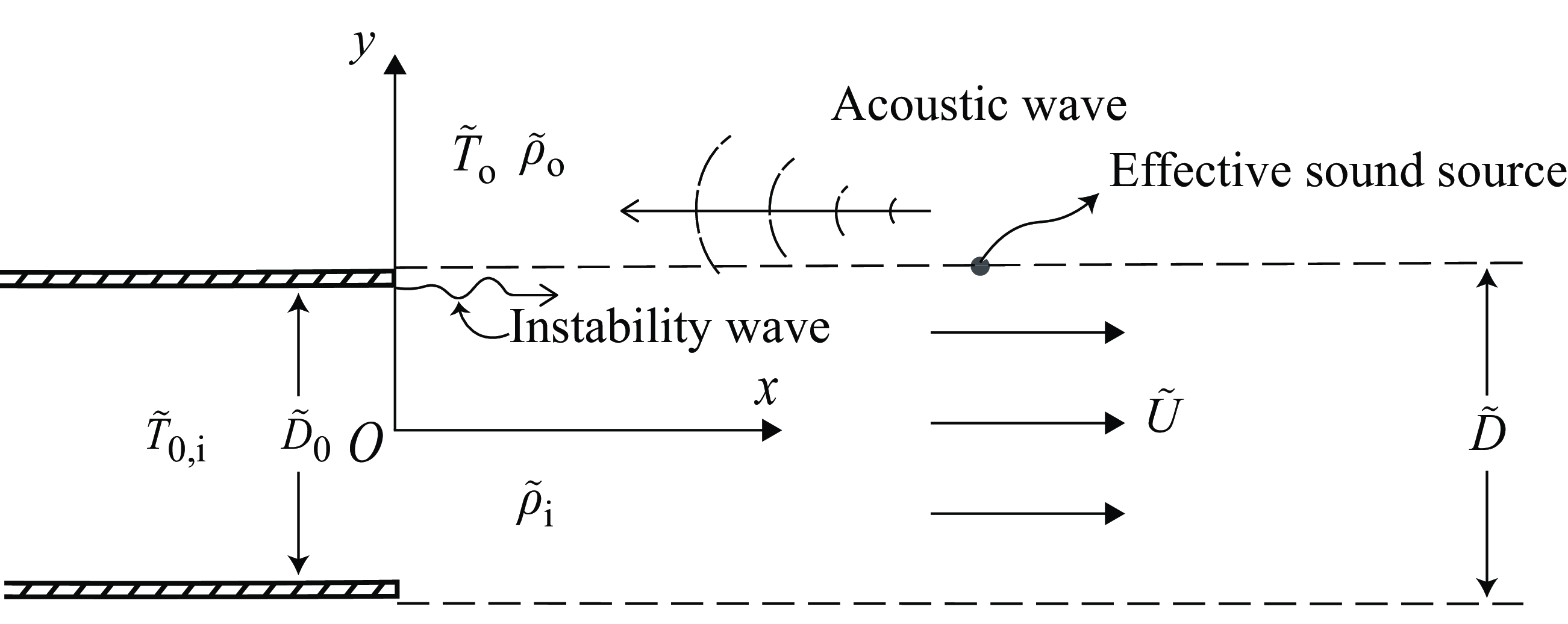
Schematic illustration is shown in figure 1. As we can see, a supersonic jet is issued from the nozzle and takes the form of a vortex sheet. The coordinate axes
 $(x,y)$
are chosen to be parallel and perpendicular to the nozzle centreline, respectively, while the origin point
 $O$
is located at the centre of the nozzle exit plane. According to Pack (Reference Pack1950), the base flow is chosen as the fully expanded jet velocity
 $\tilde {U}$
, which is different from the jet exit velocity
 $\tilde {U}_j$
. Here,
 $\tilde {D}$
is the height of the fully expanded jet. Note that
 $\tilde {D}$
is generally not equal to the height of the nozzle
 $\tilde {D}_0$
(Tam Reference Tam1972), but is less or greater than
 $\tilde {D}_0$
depending on whether the jet is overexpanded or underexpanded (Tam & Tanna Reference Tam and Tanna1982). The densities inside and outside the jet are denoted by
 $\tilde {\rho }_{\textrm {i}}$
and
 $\tilde {\rho }_{\textrm {o}}$
, respectively, while
 $\tilde {T}_{0,\textrm {i}}$
and
 $\tilde {T}_{\textrm {o}}$
represent the total reservoir temperature and the ambient temperature outside the jet, respectively. The nozzle lips, represented by two flat plates in figure 1, are assumed to be semi-infinite with a negligible thickness, extending to
 $-\infty$
in the
 $x$
direction. Downstream of the nozzle lip, an acoustic wave, with a speed of sound
 $\tilde {a}_\infty$
and a frequency of
 $\tilde {\omega }$
, is emitted from a source region and propagates upstream to the nozzle lip, triggering the instability waves.
To simplify the problem, we non-dimensionalise velocities and lengths by
 $\tilde {U}$
and
 $\tilde {D}$
, respectively. In addition, densities and temperatures are non-dimensionalised by
 $\tilde {\rho }_{\textrm {o}}$
and
 $\tilde {T}_{\textrm {o}}$
, respectively. Note that we use the symbols with a tilde to represent dimensional variables, while those without denote non-dimensional variables. For example, after the non-dimensionalisation, the jet exit velocity is
 $U_j$
and the base flow takes the form
 \begin{equation} \boldsymbol {u}_{0}= \begin{cases} 0, & |y|\gt 1/2, \\ {\boldsymbol{e}}_{x}, & |y|\leqslant 1/2, \end{cases} \end{equation}
where
 ${\boldsymbol{e}}_{x}$
is the unit vector in the
 $x$
direction.
Considering that the mean pressure outside and inside of the vortex sheet remains the same when a perfect gas is assumed, the density ratio between the outside and inside of the vortex sheet, here defined as
 $\sigma$
, is equal to
 $M_{\textrm {o}}^2 / M_{\textrm {i}}^2$
. Here,
 $M_{\textrm {o}}$
and
 $M_{\textrm {i}}$
are defined as
 $1/c_{\textrm {o}}$
and
 $1/c_{\textrm {i}}$
, respectively, where
 $c_{\textrm {o}}$
and
 $c_{\textrm {i}}$
represent the non-dimensional speed of sound outside and inside of the jet, respectively. The relation between the two Mach numbers is determined using Crocco–Busemann’s rule, i.e.
 \begin{equation} M_{\textrm {o}}=\dfrac {M_{\textrm {i}}}{\sqrt {1+\dfrac {\gamma -1}{2}M_{\textrm {i}}^2}}\nu ^{1/2}, \end{equation}
where
 $\nu$
denotes the temperature ratio between
 $\tilde {T}_{0,\textrm {i}}$
and
 $\tilde {T}_{\textrm {o}}$
, and
 $\gamma$
represents the specific heat ratio.
Schematic of the vortex-sheet flow configuration and Cartesian coordinates. The origin is fixed at the centre of the nozzle while
 $x$
- and
 $y$
-axes represent the streamwise and cross-flow coordinates, respectively.

Before proceeding to solve the problem, it is useful to examine the designed transfer function using the Buckingham
 $\pi$
theorem. As mentioned above, eight physical variables are involved in this model, i.e.
 $\tilde {D}$
,
 $\tilde {U}$
,
 $\tilde {\rho }_{\textrm {i}}$
,
 $\tilde {\rho }_{\textrm {o}}$
,
 $\tilde {T}_{0,\textrm {i}}$
,
 $\tilde {T}_{\textrm {o}}$
,
 $\tilde {a}_\infty$
and the frequency of the acoustic wave
 $\tilde {\omega }$
, while four independent dimensions can be found. Employing the Buckingham
 $\pi$
theorem, it is evident that the transfer function
 $H$
between the newly excited instability wave and the acoustic waves is related to four non-dimensional parameters. These four parameters are chosen to be the Mach number
 $M_{\textrm {i}}$
, the Strouhal number
 $\omega$
, the temperature ratio
 $\nu$
and the density ratio
 $\sigma$
. The density ratio can be calculated using
 $\nu$
and
 $M_{\textrm {i}}$
through the Crocco–Busemann rule (2.2). Therefore, there remain three independent non-dimensional parameters and our objective is to find the transfer function
 $H (M_{\textrm {i}},\omega ,\nu )$
in the subsequent analysis.
To have a realistic incident acoustic wave, we take the result obtained in the SII work (Li & Lyu Reference Li and Lyu2022, Reference Li and Lyu2023). Pack’s model was used to describe shock waves, while instability waves were calculated using the linear stability analysis. The resulting non-dimensionalised velocity potential function of the acoustic waves due to one-cell interaction can be obtained by performing the inverse Fourier transform, i.e.
 \begin{equation} \phi _{\textit{in}}(x,y)=\frac {1}{2\pi }\int _{-\infty }^{\infty }D_{\textrm {o}}(\lambda )\textrm {exp}\left(-\left(\textrm {i}\lambda x+\sqrt {\lambda ^2-\omega ^2 M_{\textrm {o}}^2}y\right)\right)\textrm {d}\lambda . \end{equation}
Herein,
 $\lambda$
denotes the streamwise wavenumber and
 $D_{\textrm {o}}(\lambda )$
represents a coefficient, which can be readily calculated when
 $M_{\textrm {o}}$
and
 $\omega$
are provided. The detailed expression of
 $D_{\textrm {o}}(\lambda )$
can be found in Appendix C. The integration in (2.3) can be estimated in the far field using the saddle point method. In this far field, the primary contribution to the integral value comes from the vicinity of the saddle point
 $\lambda _0=-\omega M_{\textrm {o}}\textrm {cos} \theta$
. As a result, the potential function can be written as follows:
 \begin{equation} \phi _{\textit{in}}(r,\theta )=\sqrt {\frac {{\omega M_{\textrm {o}}}}{{2\pi }}}\frac {\textrm {e}^{\textrm {i}\omega (M_{\textrm {o}}r-t-\pi /4)}}{\sqrt {r}}D_{\textrm {o}}(-\omega M_{\textrm {o}}\textrm {cos} \theta )\textrm {sin} \theta , \end{equation}
where
 $\theta$
denotes the observer angle with respect to the downstream direction and
 $r$
represents the distance from the screech source region to the nozzle lip. Further details on the saddle point method can be found from Crighton et al. (Reference Crighton, Dowling, Williams, Heckl and Leppington1992).
As shown in (2.4),
 $\phi _{ {in}}(r,\theta )$
depends on
 $r$
. Experimental observations indicated that the screech source was situated several shock cells downstream from the nozzle exit (Suda et al. Reference Suda, Manning and Kaji1993; Kaji & Nishijima Reference Kaji and Nishijima1996; Malla & Gutmark Reference Malla and Gutmark2017). Therefore, the streamwise distance between the source position to the nozzle lip is written as
 \begin{equation} h=n s, \end{equation}
where
 $n$
typically takes the value of 3, 4 or 5 (Suda et al. Reference Suda, Manning and Kaji1993; Li & Gao Reference Li and Gao2010; Malla & Gutmark Reference Malla and Gutmark2017) and
 $s$
denotes the shock spacing, which can be calculated using Pack’s model (Pack Reference Pack1950; Tam Reference Tam1986). Note that we assume the shock cells are equally spaced downstream of the jet flow, while in realistic jets, the shock spacing gradually decreases (Norum & Seiner Reference Norum and Seiner1982). This non-uniform spacing may change the screech frequency prediction slightly. However, in this paper, our focus is to develop a transfer function at a given frequency. Such approximation should suffice for such a purpose.
We consider the potential function of the upstream forcing
 $\Phi _{ {in}}(r,\theta )$
in the proximity of the nozzle lip, where the value of
 $y-1/2$
is relatively small compared with
 $|x|=h$
. Therefore, the distance
 $r$
in (2.4) can be approximated as
 $r\approx h$
. Similarly, we have
 $\sin \theta \approx (y-1/2)/h$
and
 $\cos \theta \approx 1$
. Consequently, in the vicinity of the nozzle, the potential function
 $\Phi _{ {in}}$
can be reformulated to a similar form to that of Crighton (Reference Crighton1992), i.e.
 \begin{equation} \Phi _{\textit{in}}(Y)=GY, \end{equation}
where
 \begin{equation} G=\sqrt {\frac {{\omega M_{\textrm {o}}}}{{2\pi }h^{3}}}D_{\textrm {o}}(\omega M_{\textrm {o}}) \textrm {e}^{\textrm {i}\omega (M_{\textrm {o}}h-\pi /4)}, \end{equation}
 \begin{equation} Y=y-\tfrac{1}{2}. \end{equation}
The goal is therefore to find the response of the jet flow due to the upstream forcing
 $GY$
near the nozzle lip. In this paper, we focus on the upper half-plane (
 $y\gt 0$
), while a similar analysis can be carried out for the lower half-plane. Considering that the time-harmonic assumption is used, the factor
 $\textrm {e}^{-\textrm {i}\omega t}$
in all the time-dependent fields is omitted for clarity in the rest of this paper. Because we assume the initial base flow to be irrotational and inviscid both inside and outside of the vortex sheet (Batchelor & Gill Reference Batchelor and Gill1962), the velocity potential induced by the incident acoustic wave near the nozzle lip can be described by a potential function. Therefore, taking into account (2.6), the total velocity potentials outside and inside the jet flow can be defined by
 \begin{equation} \Phi =GY+\phi (x,y), \end{equation}
 \begin{equation} \Psi =GY+\psi (x,y), \end{equation}
respectively, where
 $\phi$
and
 $\psi$
are the corresponding potential functions of the scattered sound fields in the region
 $y\gt 1/2$
and
 $0\leqslant y\leq 1/2$
, respectively.
It is known that
 $\phi$
and
 $\psi$
both satisfy the convective wave equation, i.e.
 \begin{equation} {\nabla }^{2}\phi +\omega ^2 M_{\textrm {o}}^2\phi =0, \end{equation}
 \begin{equation} {\nabla }^{2}\psi +\left ( \omega + \textrm {i}M_{\textrm {i}}\frac {\partial }{\partial x}\right )^2\psi =0. \end{equation}
Hard-wall conditions are imposed on
 $y=1/2$
for
 $-\infty \lt x \leq 0$
. Note that, strictly speaking, these conditions should be applied at
 $y=\tilde {D_0}/2\tilde {D}$
, which can be either less than or greater than
 $1/2$
depending on whether the jet is underexpanded or overexpanded (Tam & Tanna Reference Tam and Tanna1982). However, as mentioned earlier, the difference between
 $\tilde {D_0}/2\tilde {D}$
and
 $1/2$
is relatively small compared with the distance
 $r$
. To enable analysis progress, we neglect this difference and assume that the plate is nearly parallel to the boundary of the jet. Therefore, we obtain
 \begin{equation} \frac {\partial \phi }{\partial y}=\frac {\partial \psi }{\partial y}=-G \quad (y=1/2,\ -\infty \lt x\leq 0). \end{equation}
The absence of decay in the forcing term
 $-G$
leads to convergence issues when the Fourier transform is applied to (2.13). To circumvent this problem, Crighton (Reference Crighton1992) replaced (2.13) by
 \begin{equation} \frac {\partial \phi }{\partial y}=\frac {\partial \psi }{\partial y}=-G\textrm {e}^{\epsilon x}, \end{equation}
where
 $\epsilon$
is a real and positive term, which retains the physical characteristics of the upstream forcing near the nozzle lip but removes the forcing further upstream. We follow the same treatment here. Note that in realistic jets, the acoustic wave decays algebraically as it propagates from the downstream source region to the upstream nozzle lip. In this study, we model the behaviour of the acoustic wave near the nozzle lip using the exponential decay rate, which will be uniquely determined in § 2.3.
The kinematic and dynamic boundary conditions can be used on the vortex sheet at
 $y=1/2,\ 0\lt x\lt \infty$
, i.e.
 \begin{equation} \left (-\textrm {i} \omega +\frac {\partial }{\partial x}\right )\frac {\partial \phi }{\partial y}=-\textrm {i}\omega \frac {\partial \psi }{\partial y}, \end{equation}
 \begin{equation} -\textrm {i}\omega \sigma \phi = \left (-\textrm {i} \omega +\frac {\partial }{\partial x}\right )\psi . \end{equation}
Fourier transforms
 $\phi (k,y), \psi (k,y)$
are defined by
 \begin{gather} \phi (k,y)=\int _{-\infty }^{+\infty } \phi (x,y)\textrm {e}^{\textrm {i} k x}\textrm {d} x, \end{gather}
 \begin{gather} \psi (k,y)=\int _{-\infty }^{+\infty } \psi (x,y)\textrm {e}^{\textrm {i} k x}\textrm {d} x, \end{gather}
where
 $k$
is the wavenumber in the streamwise direction. Multiplying (2.11) and (2.12) with
 $\textrm {e}^{\textrm {i}kx}$
and subsequently integrating both expressions with respect to the variable
 $x$
, solutions to (2.11) and (2.12) can be found upon invoking the far-field boundary condition, i.e.
 \begin{equation} \phi (k,y)=\phi ^{*}(k)\textrm {e}^{-\gamma _1(k)y}, \end{equation}
 \begin{equation} \psi (k,y)=\psi _{\textrm {s}}^{*}(k)\sinh \gamma _2(k)y+\psi _{\textrm {c}}^{*}(k)\cosh \gamma _2(k)y, \end{equation}
where
 \begin{equation} \gamma _2(k)=\sqrt {k^2-(\omega +k)^2M_{\textrm {i}}^2} \quad \textrm {and} \quad \gamma _1(k)=\sqrt {k^2-\omega ^2 M_{\textrm {o}}^2}. \end{equation}
Herein,
 $\phi ^*(k)$
,
 $\psi _{\textrm {s}}^*(k)$
and
 $\psi _{\textrm {c}}^{*}(k)$
are functions of
 $k$
, whose detailed forms will be specified subsequently. To satisfy the far-field condition, the real part of
 $\gamma _{1}$
should be positive and its branch cut will be specified later. It is well known that both symmetric (varicose) and antisymmetric (sinuous) instability modes can exist inside the jet. However, for jet flows from high-aspect-ratio rectangular nozzles, the sinuous mode is dominant (Edgington-Mitchell Reference Edgington-Mitchell2019). Therefore, we consider the antisymmetric mode in this study, while the symmetric mode can be examined in a similar way should interest arise. In this case,
 $\psi (k,y)$
reduces to
 \begin{equation} \psi (k,y)=\psi ^{*}_{\textrm {s}}(k)\sinh \gamma _2(k)y. \end{equation}
In what follows, we use the Wiener–Hopf method to solve this boundary-value problem specified by (2.19), (2.22), and boundary conditions (2.14), (2.15) and (2.16). The details of the Wiener–Hopf technique can be found from Noble (Reference Noble1958). Using (2.14), we can obtain
 \begin{equation} \phi ^{\prime }(k,1/2)=\phi _{+}^{\prime }(k,1/2)+\frac {\textrm {i}G}{k-\textrm {i}\epsilon }, \end{equation}
where the prime represents the first derivative with respect to
 $y$
and
 $\phi _{+}(k,1/2)$
is defined by
 \begin{equation} \phi _{+}(k,1/2)=\int _{0}^{\infty }\phi (x,1/2)\textrm {e}^{\textrm {i}k x}\textrm {d}x. \end{equation}
Considering the kinematic boundary condition across the vortex sheet, i.e. (2.15), and the boundary conditions imposed on the nozzle lip, i.e. (2.14), we have
 \begin{equation} (k-\textrm {i}\epsilon )\psi ^{*}_{\textrm {s}}(k)\cosh \gamma _2(k)/2-\frac {G}{\omega }\epsilon =-\left (1+\frac {k}{\omega }\right )(k-\textrm {i}\epsilon )\frac {\gamma _1(k)}{\gamma _2(k)}\phi ^{*}(k)\textrm {e}^{-\gamma _1(k)/2}. \end{equation}
Following Crighton (Reference Crighton1992), the term
 $\dfrac {G}{\omega }\epsilon$
on the left-hand side of (2.25) is omitted, considering that
 $\epsilon$
is a small term.
Now, we define a new function related to the difference between the pressures outside and inside the vortex sheet as
 $D(k,1/2)$
, i.e.
 \begin{equation} D(k,1/2)=\int _{-\infty }^{\infty } \left (-\textrm {i}\omega \sigma \phi (x,1/2)-\left (-\textrm {i}\omega +\frac {\partial }{\partial x}\right )\psi (x,1/2)\right )\textrm {e}^{\textrm {i}k x}\textrm {d}x. \end{equation}
Due to the continuity of the pressure across the vortex sheet, i.e. (2.16), the pressure difference vanishes when
 $x\gt 0$
. Therefore,
 $D(k,1/2)$
reduces to
 \begin{equation} \begin{aligned} D(k,1/2) &= -\textrm {i}\omega \sigma \phi _{-}(k,1/2)-(-\textrm {i}\omega -\textrm {i}k)\psi _{-}(k,1/2)+\psi _0, \end{aligned} \end{equation}
where
 \begin{gather} \phi _{-}(k,1/2)=\int _{-\infty }^{0}\phi (x,1/2)\textrm {e}^{\textrm {i}k x}\textrm {d}x \quad \textrm {and} \quad \psi _{-}(k,1/2)=\int _{-\infty }^{0}\psi (x,1/2)\textrm {e}^{\textrm {i}k x}\textrm {d}x, \end{gather}
and
 $\psi _0$
denotes the finite value of
 $\psi (x,y)$
at the position
 $(0,1/2)$
. Substituting (2.19) and (2.22) into (2.27), we obtain
 \begin{equation} D(k,1/2)=-\textrm {i}\omega \sigma \phi ^{*}(k)\textrm {e}^{-\gamma _1(k)/2}-(-\textrm {i}\omega -\textrm {i}k)\psi ^{*}_{\textrm {s}}(k)\sinh \gamma _2(k)/2. \end{equation}
Combining (2.23), (2.25), (2.27) and (2.29) yields
 \begin{equation} \phi _{+}^{\prime }(k,1/2)+\frac {\textrm {i}G}{k-\textrm {i}\epsilon }=K(k)F_{-}(k), \end{equation}
where
 \begin{equation} K(k)=\frac {1}{\dfrac {\sigma }{\gamma _1(k)}+\dfrac {(1+k/\omega )^2\tanh \gamma _2(k)/2}{\gamma _2(k)}}, \end{equation}
 \begin{equation} F_{-}(k)=(1+k/{\omega })\psi _{-}(k,1/2)-\sigma \phi _{-}(k,1/2)-{\textrm {i}}\psi _0/{\omega }. \end{equation}
Equation (2.30) represents the Wiener–Hopf equation we aim to solve, with the kernel given by
 $K(k)$
. Here,
 $1/K(k)=0$
represents the dispersion relation of the antisymmetric mode of the jet instability wave. It can be seen that as
 $|k|\rightarrow \infty$
,
 $|K(k)|\rightarrow |k|^{-1}$
. Now, following the procedures of the Wiener–Hopf method, we assume that the kernel can be decomposed into
 \begin{equation} K(k)=K_{+}(k)K_{-}(k), \end{equation}
where
 $K_{+}(k)$
and
 $K_{-}(k)$
are analytic and non-zero in the upper and lower half-planes of
 $k$
, respectively. Meanwhile, both
 $K_{+}(k)$
and
 $K_{-}(k)$
behave as
 $O(k^{-1/2})$
as
 $k$
approaches infinity. The actual decomposition will be shown in § 2.2. Routine use of Wiener–Hopf decomposition leads to
 \begin{equation} \frac {\phi _{+}^{\prime }(k,1/2)}{K_{+}(k)}+\left (\frac {1}{K_{+}(k)}-\frac {1}{K_{+}(\textrm {i}\epsilon )}\right )\frac {\textrm {i}G}{k-\textrm {i}\epsilon }=E(k), \end{equation}
 \begin{equation} K_{-}(k)F_{-}(k)-\frac {1}{K_{+}(\textrm {i}\epsilon )}\frac {\textrm {i}G}{k-\textrm {i}\epsilon }=E(k). \end{equation}
Here,
 $E(k)$
is an entire function of
 $k$
. Due to the Kutta condition (Crighton Reference Crighton1985),
 $\phi (x,1/2)$
behaves like
 $x^{3/2}$
near the nozzle lip. The corresponding value of
 $ \phi ^\prime (x,1/2)$
is therefore
 $O(x^{1/2})$
. It follows that
 $\phi _{+}^{\prime }(k,1/2)\rightarrow k^{-3/2}$
as
 $k\rightarrow \infty$
(Erfelyi Reference Erfelyi1958). Thus, from Liouville’s theorem,
 \begin{equation} E(k)\equiv 0. \end{equation}
From (2.23) and (2.34),
 $\phi ^{\prime }(k,1/2)$
can be readily solved, i.e.
 \begin{equation} \phi ^{\prime }(k,1/2)=\frac {\textrm {i}G}{k-\textrm {i}\epsilon }\frac {K_{+}(k)}{K_{+}(\textrm {i}\epsilon )}. \end{equation}
It can be seen that
 $\phi ^{\prime }(k,1/2)$
is
 $O(k^{-3/2})$
as
 $|k|$
approaches infinity in the upper half-plane. The corresponding velocity component
 $\phi ^\prime (x,y)$
behaves as
 $x^{1/2}$
when
 $x\rightarrow 0$
, which leads to singularity in
 $\psi ^\prime (x,y)$
due to (2.15). Therefore, (2.37) leads to singular behaviour when
 $|k|\rightarrow \infty$
, where (2.37) can be approximated by (Crighton Reference Crighton1992)
 \begin{equation} \frac {\textrm {i}G}{K_{+}(\textrm {i}\epsilon )}\frac {K_{+}(k)}{k}. \end{equation}
This part will be further discussed in § 2.3, where the unsteady Kutta condition is used to determine the new instability wave by removing the emerging singularity.
2.2. Kernel decomposition
In this section, we factor the kernel
 $K(k)$
into
 $K_{+}(k)$
and
 $K_{-}(k)$
, which is the essential step of the Wiener–Hopf technique. Before proceeding with the decomposition of the kernel, it is necessary to properly define the branch cuts of
 $K(k)$
. To ensure that the real part of
 $\gamma _{1}$
is positive as
 $|k|\rightarrow \infty$
along the integration path (which becomes relevant when conducting the inverse Fourier transform if we are interested in calculating the scattered sound field), the branch cuts of
 $\gamma _{1}$
passing the branch points
 $k=\pm \omega M_{\textrm {o}}$
are chosen to extend to the upper and lower half-plane, respectively, as shown in figure 2(a). The branch is selected in such a way that
 $\textrm {arg}(\gamma _1)=-\pi /2$
at
 $k=\textrm {i}$
. However, the branch points of
 $\gamma _{2}$
are determined as
 $M_{1}=-\omega M_{\textrm {i}}/(M_{\textrm {i}}+1)$
and
 $M_{2}=-\omega M_{\textrm {i}}/(M_{\textrm {i}}-1)$
. The branch cuts passing
 $M_{1}$
and
 $M_{2}$
are chosen to extend to the lower and upper half-plane, respectively, for the convenience of the kernel decomposition. The branch of
 $\gamma _2$
is selected to ensure that
 $\textrm {arg}(\gamma _2)=-\pi /2$
at
 $k=\textrm {i}$
. Due to the choice of the branch cuts, we can find that
 $\gamma _2(k)/\gamma _1(k)\rightarrow \sqrt {1-M_{\textrm {i}}^2}$
, as
 $\omega \rightarrow 0$
and
 $k\rightarrow O(1)$
.
(a) Schematic of the branch points, branch cuts and the integration path in the complex
 $k$
plane. (b) Schematic of the deformed integration path in the complex
 $t$
plane.

The kernel can be rewritten as
 \begin{equation} K(k)=\frac {\gamma _2(k)}{\sigma \gamma _2(k)/\gamma _1(k)+(1+k/\omega )^2\tanh \gamma _2(k)/2}. \end{equation}
A proper decomposition of
 $\gamma _2(k)$
is evident, i.e.
 $\gamma _2(k)=\sqrt {k-M_1}\sqrt {k-M_2}$
. Thus, in what follows, we only focus on the denominator, which we refer to as
 $Q(k)$
. It can be seen that
 $Q(k)$
depends on the dispersion relation of the antisymmetric mode of the jet instability wave. This dispersion relation describes several types of waves present in the jet, determined by its structural characteristics such as branches, zeros and poles. These information can be maintained if the kernel is decomposed by means of matched asymptotic expansions (Crighton Reference Crighton1992, Reference Crighton2001). To use this strategy, a small parameter should be specified as the basis for the expansion. This parameter should not only be small but can also be contained by the kernel. We introduce
 $S=\omega (M_{\textrm {i}}-1)^2$
as this parameter. In what follows, the complicated kernel is replaced by a simpler one by asymptotic expansions based on
 $S$
. Overlapping approximations are subsequently applied to guarantee the validity of the decomposition over the whole range of the wavenumber
 $k$
. The final result is obtained by a multiplicative composite approximation.
We first assume
 $k=O(1)$
and let
 $\omega \rightarrow 0$
. The first term of
 $Q(k)$
, i.e.
 $\sigma \gamma _2(k)/\gamma _1(k)$
, reduces to
 $\sigma \sqrt {1-M_{\textrm {i}}^2}$
and
 $Q(k)$
can be approximated as
 \begin{equation} \begin{aligned} Q(k) &\approx \left (\frac {k}{\omega }\right )^2\tanh \sqrt {\left(1-M_{\textrm {i}}^2\right)k^2}/2. \end{aligned} \end{equation}
The term
 $\sqrt {(1-M_{\textrm {i}}^2)k^2}$
is supposed to maintain the branch cut chosen for
 $\gamma _2(k)$
. For brevity, we rewrite
 $\sqrt {(1-M_{\textrm {i}}^2)k^2}$
as
 $\sqrt {1-M_{\textrm {i}}^2k^{*}}$
, where the script
 $^*$
represents that this parameter retains the specified branch cuts.
Now, we introduce the small parameter
 $S=\omega (M_{\textrm {i}}-1)^2$
and a new scaled wavenumber according to
 \begin{equation} q=k/S^{\frac {3}{4}}. \end{equation}
By assuming
 $S\rightarrow 0$
and
 $q\rightarrow O(1)$
, we can expand
 $Q(k)$
in (2.39) based on the small parameter
 $S$
(using methods of Taylor expansion), i.e.
 \begin{equation} \begin{aligned} Q(k)&\approx \sqrt {1-M_{\textrm {i}}^2}\left(\sigma -\frac {\sigma M_{\textrm {i}}^2S^{1/4}}{(M_{\textrm {i}}-1)^2\left(1-M_{\textrm {i}}^2\right)q^{*}}+\frac {1}{2}(M_{\textrm {i}}-1)^4S^{1/4}q^{2}q^{*}\right), \end{aligned} \end{equation}
where
 $q^*=k^*/S^{\frac {3}{4}}$
. Note that despite the small parameter
 $S\sim o(1)$
, the quantities
 $S^{1/4}\sim O(1)$
. To put this into perspective, let us consider an example with
 $M_{\textrm {i}}=1.1$
. At the screech frequency, employing Powell’s original model yields
 $S=0.026$
(with
 $\kappa =0.6$
and
 $\nu =1$
). However,
 $S^{1/4}=0.40$
, which is of the order of unity. The scale separation under other jet Mach numbers is discussed in Appendix A. This demonstrates that although
 $S$
itself may be small, its corresponding fractional power can still have magnitudes of the order of unity in our interested application.
We can show that (2.40) and (2.42) do overlap, as
 $k\rightarrow 0$
and
 $q\rightarrow \infty$
, respectively, with common value
 $({1}/{2})\sqrt {1-M_{\textrm {i}}^2}(M_{\textrm {i}}-1)^4S^{1/4}q^{2}q^{*}$
. A multiplicative composite approximation then reads
 \begin{equation} \begin{aligned} Q(k)&\approx \sqrt {1-M_{\textrm {i}}^2} \frac {\tanh \dfrac {1}{2}\sqrt {1-M_{\textrm {i}}^2} k}{\dfrac {1}{2}\sqrt {1-M_{\textrm {i}}^2} k} \frac {1}{q^{*}}R(q), \end{aligned} \end{equation}
where
 \begin{equation} R(q)=\sigma q^{*}-\frac {\sigma M_{\textrm {i}}^2S^{1/4}}{(M_{\textrm {i}}-1)^2\left(1-M_{\textrm {i}}^2\right)}+\frac {1}{2}(M_{\textrm {i}}-1)^4S^{1/4}q^{4}. \end{equation}
This approximation strategy enables direct calculation of the wavenumber for the sinuous mode of the jet instability wave. To validate the decomposition, the wavenumber analytically obtained by letting
 $Q(k)$
in (2.43) equal to 0 is compared with that numerically solved from the dispersion relation
 $1/K(k) = 0$
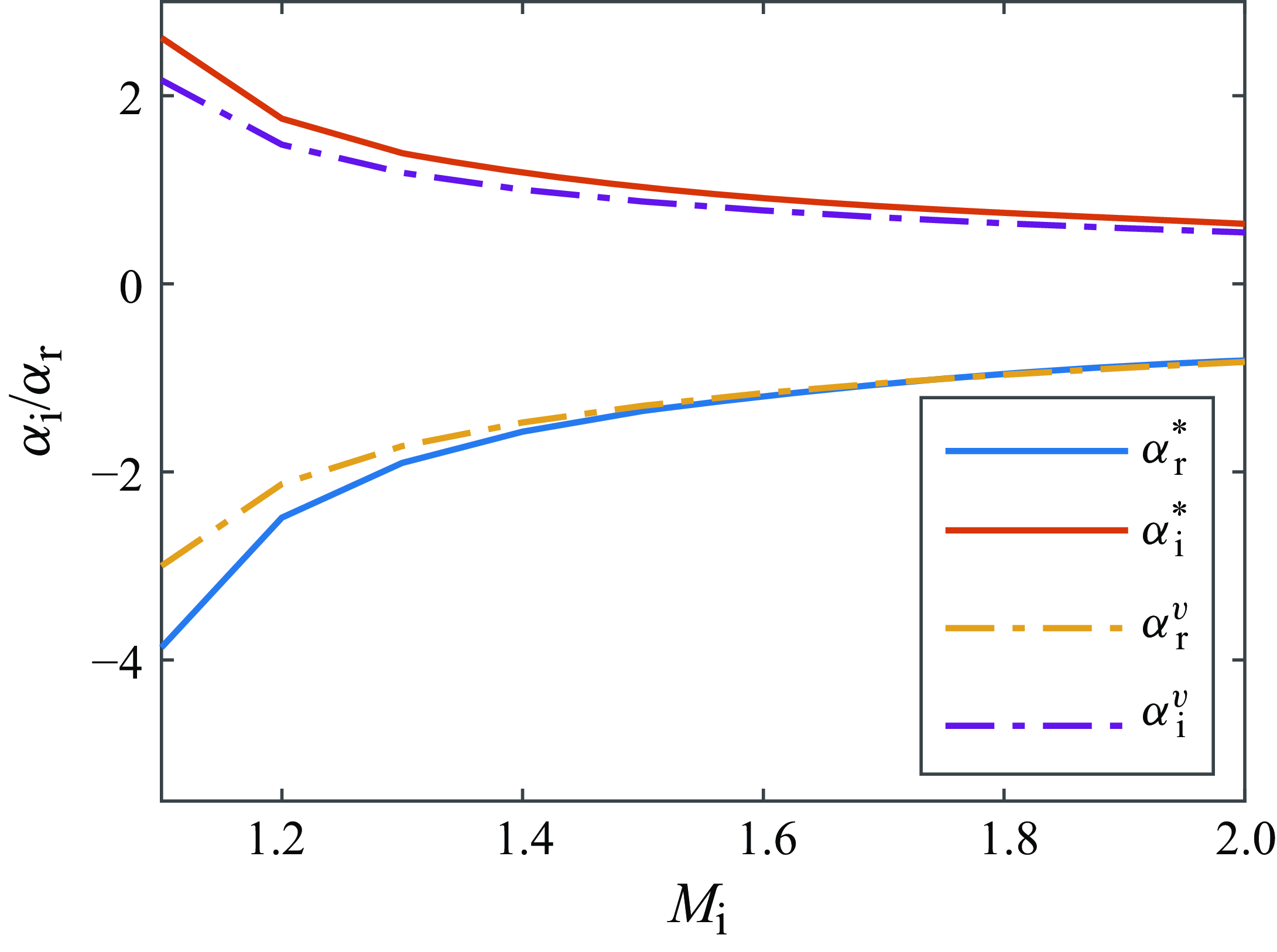
. As shown in figure 3, the agreement between the two wavenumbers is good when
 $M_{\textrm {i}} \gt 1.2$
, which corresponds to the screech frequency in the range of
 $\omega \lesssim 1.8$
. This indicates that to accurately estimate the wavenumber, frequency should be a small term. Additional validations under other operation conditions are provided in Appendix A.
Comparison between the wavenumbers of the sinuous mode of the jet instability wave obtained by the decomposed kernel (2.43) and the dispersion relation.
 $\alpha ^{*}$
and
 $\alpha ^{v}$
denote the wavenumber calculated from the decomposed kernel and
 $M(k)$
, respectively, while the subscripts
 $_r$
and
 $_i$
represent the real and imaginary part of the parameter, respectively.
 $\sigma$
is assumed to be
 $1$
.

We are now in a position to factor the function
 $Q(k)$
. From Noble (Reference Noble1958),
 $({\tanh \sqrt {1-M_{\textrm {i}}^2} k/2})/({\sqrt {1-M_{\textrm {i}}^2} k/2})$
can be decomposed to
 \begin{equation} \begin{aligned} \frac {\tanh \dfrac {1}{2}\sqrt {1-M_{\textrm {i}}^2} k}{\dfrac {1}{2}\sqrt {1-M_{\textrm {i}}^2} k} &= T_{+}(k)T_{-}(k), \end{aligned} \end{equation}
where
 \begin{gather} T_+(k)=\frac {\Gamma \left(1/2+\sqrt {M_{\textrm {i}}^2-1}k/2\pi \right)}{\pi ^{1/2}\Gamma \left(1+\sqrt {M_{\textrm {i}}^2-1}k/2\pi \right)},\quad T_-(k)=\frac {\Gamma \left(1/2-\sqrt {M_{\textrm {i}}^2-1}k/2\pi \right)}{\pi ^{1/2}\Gamma \left(1-\sqrt {M_{\textrm {i}}^2-1}k/2\pi \right)}. \end{gather}
Here,
 $\Gamma$
represents the Gamma function. The decomposition of
 $1/q^*$
reads
 \begin{equation} \begin{aligned} \frac {1}{q^*} &=\mathcal {Q}_{+}(q)\mathcal {Q}_{-}(q), \end{aligned} \end{equation}
where
 \begin{equation} \mathcal {Q}_{+}(q)=\frac {1}{\sqrt {q+0}},\quad \mathcal {Q}_{-}(q)=\frac {1}{\sqrt {q-0}}. \end{equation}
Naturally, the branch cut of
 $\mathcal {Q}_{+}$
and
 $\mathcal {Q}_{-}$
is from
 $-0$
to
 $-\textrm {i}\infty$
and from
 $+0$
to
 $+\textrm {i}\infty$
, respectively.
The decomposition of
 $R(q)$
, however, is very difficult due to the presence of
 $q^{*}$
in (2.44).
To decompose
 $R(q)$
, we let
 $q$
be real first (Crighton Reference Crighton1992), so that
 $q^{*}=|q|$
. This is reasonable considering that the overlap of the two half-planes will converge to the real axis in the complex
 $k$
plane. Assuming that
 $R(q)$
can be decomposed to
 $R(q)=R_{+}(q)R_{-}(q)$
and taking the first derivative of
 $\textrm {ln}R(q)$
, we obtain
 \begin{equation} \frac {\textrm {d}}{\textrm {d}q}\textrm {ln}R_{+}(q)+\frac {\textrm {d}}{\textrm {d}q}\textrm {ln}R_{-}(q)=\frac {4q^3+a_1 |q|/q}{q^4+a_1|q|+a_0}, \end{equation}
where
 \begin{align} a_0=2\sigma M_{\textrm {i}}^2(M_{\textrm {i}}-1)^{-6}\left(M_{\textrm {i}}^2-1\right)^{-1},\nonumber \\ a_1=2\sigma (M_{\textrm {i}}-1)^{-4}S^{-1/4}.\qquad \end{align}
Multiplying the numerator and the denominator of the right-hand side term in (2.49) by
 $q^4-a_1|q|+a_0$
, (2.49) can be written as
 \begin{equation} \frac {\textrm {d}}{\textrm {d}q}\textrm {ln}R_{+}(q)+\frac {\textrm {d}}{\textrm {d}q}\textrm {ln}R_{-}(q)=\frac {(4q^3+a_1 |q|/q)(q^4-a_1|q|+a_0)}{(q^4+a_0)^2-a_1^2q^2}. \end{equation}
The zeros of the denominator
 $(q^4+a_0)^2-a_1^2q^2$
are defined as
 $q_n, n=1,\ldots ,8$
, which can be obtained by Ferrari’s formula. The details are provided in Appendix A. With the knowledge of these zeros, we can now reorganise (2.51) as
 \begin{equation} \begin{aligned} \frac {\textrm {d}}{\textrm {d} q} \ln \left (\frac {R_{+}(q)}{\prod _{n=5}^8\left (q-q_n\right )^{1/2}}\right )+\frac {\textrm {d}}{\textrm {d} q} \ln & \left (\frac {R_{-}(q)}{\prod _{n=1}^4\left (q-q_n\right )^{1/2}}\right ) \\ &=\sum _{n=1}^4 \xi _n \frac {|q|}{\left (q-q_n\right )}+ \sum _{n=5}^8\xi _n \frac {|q|}{\left (q-q_n\right )}+\frac {a_1 }{a_0 }\frac {|q|}{q}, \end{aligned} \end{equation}
where
 \begin{equation} \xi _n =\frac {-3a_1q_n^4+a_0a_1}{2q_n^2\left(4q_n^6+4a_0q_n^2-a_1^2\right)}. \end{equation}
The detailed derivation from (2.51) to (2.52) can be found in Appendix B. For brevity, we can define
 $\xi _9=a_1/a_0$
and
 $q_9=0$
. With these definitions, it is straightforward to find
 \begin{equation} \sum _{n=1}^9 \xi _n q_n=\sum _{n=1}^9 \xi _n=0. \end{equation}
An addictive decomposition of
 $|q|$
is now introduced, i.e.
 \begin{eqnarray} |q|&=&Q_{+}(q)+Q_{-}(q), \end{eqnarray}
where
 \begin{equation} Q_{+}(q)=q/2+\frac {\textrm {i}q}{\pi }\ln _{+}q,\quad Q_{-}(q)=q/2-\frac {\textrm {i}q}{\pi }\ln _{-}q. \end{equation}
The branch cuts of
 $\ln _{+}$
and
 $\ln _{-}$
extend from
 $0$
to
 $-\textrm {i}\infty$
and from
 $0$
to
 $+\textrm {i}\infty$
, respectively. The choice of the branch cut leads to
 \begin{equation} Q_+(q)=Q_{-}(-q). \end{equation}
Using the addictive decomposition (2.55) and the two identities (2.54) and (2.57), the right-hand side of (2.52) can obtain a similar addictive factorisation and
 $R_{+}(q)$
can be finally found as
 \begin{equation} R_{+}(q)=\prod _{n=5}^8(q-q_n)^{1/2}\textrm {exp}\left (-\frac {\textrm i}{\pi }\sum _{n=1}^{8}\xi _n q_n\int _{q/q_n }^{\infty }\frac {\ln _{+}t}{t-1}\textrm {d}t +\sum _{n=5}^{8}{\xi _n q_n}\int _{q/q_n }^{\infty }\frac {1}{t-1}\textrm {d}t \right ). \end{equation}
The detailed derivation from (2.52) to (2.58) can be found in Appendix B.
To evaluate the integral in (2.58), as shown in figure 2(b), we deform the integration path in (2.58) from
 $q/q_n$
to the point
 $\textrm {e}^{\pi \textrm {i}/2}$
, then along a unit circle to reach
 $q/q_n=1$
situated on the real axis, and finally along a ray from
 $q/q_n=1$
to
 $\infty$
. Using the identity (2.54), we can evaluate (2.58) to obtain
 \begin{equation} \begin{aligned} R_{+}(q)=\prod _{n=5}^8(q-q_n)^{1/2}\textrm {exp}\left(-\frac {\textrm i}{\pi }\sum _{n=1}^{8}\xi _n q_n \textrm {Li}_2(1-q/q_n) - \sum _{n=5}^{8}{\xi _n q_n}\textrm {ln}_+ \frac {q}{q_n}\right). \end{aligned} \end{equation}
Here,
 $\textrm {Li}_2$
represents the polylogarithm function of the second order (Gradshteyn & Ryzhik Reference Gradshteyn and Ryzhik1980).
Using (2.46), (2.48) and (2.59), we obtain the final form of
 $K_{+}$
, i.e.
 \begin{equation} K_{+}(k)=\frac {\sqrt {k-M_2}}{T_{+}(k)R_{+}(k/S^{3/4})\mathcal {Q}_{+}(k/S^{3/4})}. \end{equation}
A complete expression of
 $K_{+}$
is
 \begin{equation} \begin{aligned} K_{+}(k)=\sqrt {\pi }&\frac {\Gamma \left(1+\sqrt {M_{\textrm {i}}^2-1}k/2\pi \right)}{\Gamma \left(1/2+\sqrt {M_{\textrm {i}}^2-1}k/2\pi \right)}\frac {\sqrt {k-M_2}\sqrt {k/S^{3/4}+0}}{\prod _{n=5}^8(q-q_n)^{1/2}} \\ &\textrm {exp}\left(\frac {\textrm i}{\pi }\sum _{n=1}^{8}\xi _n q_n \textrm {Li}_2(1-q/q_n) + \sum _{n=5}^{8}{\xi _n q_n}\textrm {ln}_+ \frac {q}{q_n}\right). \end{aligned} \end{equation}
As
 $k\rightarrow 0$
, the Taylor expansion of
 $K_{+}(k)$
reduces to
 \begin{equation} K_{+}(k)\approx \frac {\textrm {i}\pi \sqrt {M_2}}{\mathcal {C}S^{3/8}}{\sqrt {k}}+O\left(k^{3/2}\right). \end{equation}
Here, the constant
 $\mathcal {C}$
is defined as
 $\mathcal {C}=\prod _{n=5}^{8}q_n^{1/2}$
. Equation (2.62) will be used to determine
 $\epsilon$
in § 2.3.
2.3. Instability waves excited by the acoustic waves at the nozzle lip
Under the excitation of the acoustic wave, new instability waves would emerge near the nozzle lip (Crighton Reference Crighton1985). We can determine this instability wave by imposing the unsteady Kutta condition at the nozzle lip (Crighton Reference Crighton1981). Following Crighton (Reference Crighton1972) and considering that we focus on the upper half-plane (
 $y\gt 1/2$
), we assume that the excited instability wave can be represented by
 \begin{equation} \phi ^{*}=\mathcal {A}\textrm {e}^{-\textrm {i}\mathcal {K}x-\gamma (\mathcal {K})y}, \end{equation}
where
 $\mathcal {A}$
represents the amplitude of the instability wave and
 $\gamma (\mathcal {K})$
is defined by
 $\gamma (\mathcal {K})=\sqrt {\mathcal {K}^{2}-\omega ^2 M_{\textrm {o}}^2}$
. The parameter
 $\mathcal {K}$
denotes the wavenumber of the instability waves of the antisymmetric mode and its determination is outlined in Appendix A. The choice of the form in (2.63) is believed to be reasonable, particularly considering the sinuous nature exhibited by both the upstream forcing and the scattered acoustic field.
The instability wave then propagates downstream and subsequently interacts with the shock structures (Powell Reference Powell1953b
; Suda et al. Reference Suda, Manning and Kaji1993; Edgington-Mitchell et al. Reference Edgington-Mitchell, Wang, Nogueira, Schmidt, Jaunet, Duke, Jordan and Towne2021). This interaction leads to the emission of sound, which serves as the upstream forcing and completes the screech feedback loop. To determine the instability amplitude
 $\mathcal {A}$
in (2.63), we first calculate the scattered field resulting from the newly excited instability wave at the nozzle lip. The singular component within the resulting scattered field needs to be eliminated using the singularity in (2.38). This process fixes the value of
 $\mathcal {A}$
to satisfy the unsteady Kutta condition.
Replacing the forcing term
 $GY$
in (2.9) and (2.10) with
 $\phi ^{*}$
while following the same procedures outlined in § 2.1, we obtain the scattered field due to the presence of the instability wave, i.e.
 \begin{equation} \phi ^{*^\prime }_{+}(k,1/2)=\frac {\textrm {i}\mathcal {A}\gamma (\mathcal {K})\textrm {e}^{-\gamma (\mathcal {K})/2}}{k-\mathcal {K}}\left (1-\frac {K_{+}(k)}{K_{+}(\mathcal {K})}\right ). \end{equation}
The component of
 $\phi ^{*^\prime }_{+}(k)$
similar to (2.38) that leads to singularity is
 \begin{equation} -\frac {\textrm {i}\mathcal {A}\gamma (\mathcal {K})\textrm {e}^{-\gamma (\mathcal {K})/2}}{K_{+}(\mathcal {K})}\left (\frac {K_{+}(k)}{k}\right ). \end{equation}
The unsteady Kutta condition demands no singularity in the vicinity of
 $r\rightarrow 0$
; therefore, from (2.38) and (2.65), we must have
 \begin{equation} \frac {\textrm {i}G}{K_{+}(\textrm {i}\epsilon )} -\frac {\textrm {i}\mathcal {A}\gamma (\mathcal {K})\textrm {e}^{-\gamma (\mathcal {K})/2}}{K_{+}(\mathcal {K})}=0. \end{equation}
The parameter
 $G$
and the kernel function
 $K_{+}$
are defined by (2.7) and (2.60), respectively. To evaluate
 $\mathcal {A}$
, we need to determine the small parameter
 $\epsilon$
, which seems to be an arbitrary value introduced to address the issue of non-convergence. However,
 $\epsilon$
in fact has a physics-imposed value and we may uniquely determine it by re-evaluating the problem without approximations.
First, replace the forcing term
 $GY$
in (2.9) and (2.10) by
 \begin{equation} F(h)=\frac {1}{2\pi }\int _{-\infty }^{\infty }D_{{\textrm {o}}}(\lambda )\textrm {exp}(-\textrm {i}\lambda h)\textrm {d}\lambda . \end{equation}
Then the Wiener–Hopf equation (2.30) takes a new form, i.e.
 \begin{equation} \phi _{+}^{\prime }(k,1/2)+\mathcal {F}(k)=K(k)F_{-}(k). \end{equation}
Here,
 \begin{equation} \begin{aligned} \mathcal {F}(k) &= \int _{-\infty }^{0} \int _{0}^{\infty } \mathcal {G}(\zeta ^{*})\textrm {exp}(\zeta ^{*} x) \textrm {e}^{\textrm {i}kx} \textrm {d}\zeta ^{*} \textrm {d}x, \end{aligned} \end{equation}
where
 $\zeta ^{*}=-\textrm {i}\lambda$
, and the form of
 $\mathcal {G}(\zeta ^{*})$
is shown in Appendix B. If we intend to completely account for the effect of the upstream forcing, we can replace
 $G$
by
 $\mathcal {G}(\zeta ^{*})$
and
 $\epsilon$
by
 $\zeta ^{*}$
, and then carry out the integration from
 $0$
to
 $\infty$
. The mathematical proof of this procedure can be found in Appendix C. Thus, it follows that
 \begin{equation} \frac {G}{K_{+}(\textrm {i}\epsilon )}=\int _{0}^{\infty } \frac {\mathcal {G}(\zeta ^{*})}{K_{+}(\textrm {i}\zeta ^{*})} \textrm {d}\zeta ^{*}. \end{equation}
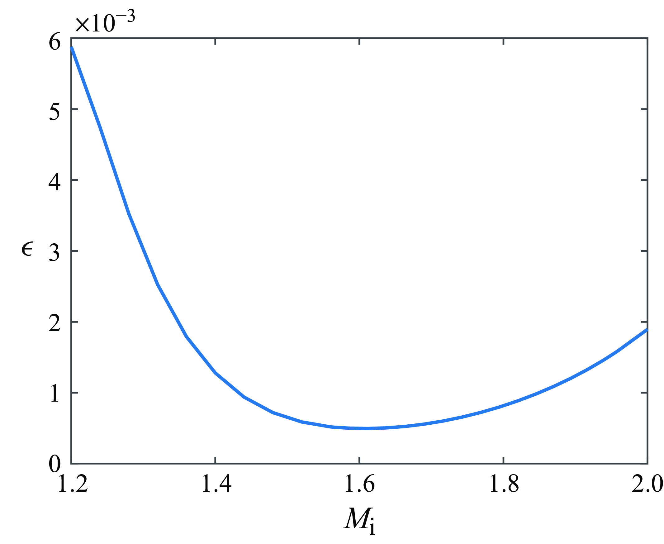
Value of the parameter
 $\epsilon$
in the range of
 $1.2\lt M_{\textrm {i}}\lt 2$
at the screeching frequency. The frequency is obtained by the original formula (1.1) proposed by Powell (Reference Powell1953a
).

The integration on the right-hand side of (2.70) can be evaluated using Watson’s lemma. On the left-hand side of (2.70), given that
 $\epsilon$
is a small term,
 $K_{+}(\textrm {i}\epsilon )$
can be evaluated employing its Taylor expansion. By combining (2.62) and (C7), we have
 \begin{equation} \epsilon =-\frac {\textrm {i}G^2h^3}{\pi \mathcal {G}^2(0)}. \end{equation}
To verify that
 $\epsilon$
is a small term, we calculate it using (2.71) and plot it in figure 4. The angular frequency of the instability wave is calculated using the original formula (1.1) proposed by Powell (Reference Powell1953a
). Figure 4 shows that within the range of
 $1.2\lt M_{\textrm {i}}\lt 2$
, the value of
 $\epsilon$
initially decreases from its maximal value of
 $5.9\times 10^{-3}$
at
 $M_{\textrm {i}}=1.2$
to
 $4.9\times 10^{-4}$
at
 $M_{\textrm {i}}=1.6$
, and then gradually increases to approximately
 $1.9\times 10^{-3}$
at
 $M_{\textrm {i}}=2$
. In the entire Mach number region,
 $\epsilon$
is small, ensuring the validity of using Taylor expansion in (2.62) and the omission of
 $G\epsilon /\omega$
in (2.25).
Having obtained all the parameters, the instability wave is found to be
 \begin{equation} \phi ^{*}(0, 1/2)=\frac {G K_{+}(\mathcal {K})}{\gamma (\mathcal {K})K_{+}(\textrm {i}\epsilon )}. \end{equation}
This equation enables us to define the important transfer function, i.e.
 \begin{equation} {H}(\omega , M_{\textrm {i}}, \nu )=\frac {K_{+}(\mathcal {K})}{\gamma (\mathcal {K})K_{+}(\textrm {i}\epsilon )}, \end{equation}
where
 $K_{+}$
is given by (2.60),
 $\mathcal {K}$
by (A7),
 $\gamma (\mathcal {K})=\sqrt {\mathcal {K}^{2}-\omega ^2 M_{\textrm {o}}^2}$
and
 $\epsilon$
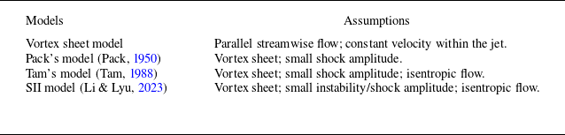
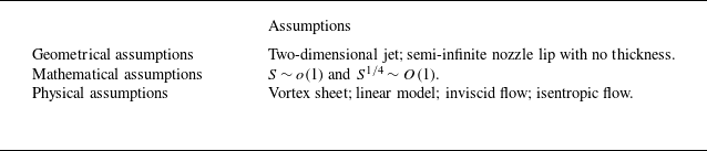
by (2.71). This transfer function describes the linear mapping between the newly excited instability waves and the upstream propagating acoustic waves. For clarity, Appendix D provides a summary of the established models upon which the present model is built, the models used for validation and the underlying assumptions for these models. Additionally, the fundamental assumptions employed in developing the transfer function are also outlined in Appendix D. Using this function, both the scattering efficiency and the phase delay between these two waves can be readily examined.
3. Results
We first investigate the behaviour of the transfer function
 $H$
under two typical screech conditions, i.e.
 $M_{\textrm {i}}=1.3$
and
 $M_{\textrm {i}}=1.5$
. We also consider the effects of the temperature by showing results at three temperature ratios, i.e.
 $\nu =1$
, 2 and 3. The amplitude, i.e. the scattering efficiency, and the phase of
 $H$
are shown in figure 5. Note that the phase is defined in the range
 $0\leq \textrm {arg}(H)\lt 2\pi$
. Considering that the asymptotic expansion yields favourable approximation when
 $M_{\textrm {i}}\gt 1.2$
, which corresponds to screech frequency within the range of
 $1\lt \omega \lt 3$
, only the frequency range from 1 to 3 is examined. Figures 5(a) and 5(c) show that the scattering efficiency
 $|H|$
displays multiple peaks and valleys as the frequency varies. In both cases,
 $|H|$
is less than
 $5\,\%$
and decreases to
 $2\,\%_0$
at certain frequencies. Note that the temperature has a mild impact on the scattering efficiency. Specifically, as the temperature ratio increases, the scattering efficiency decreases slightly. Regarding the phase delay, figures 5(b) and 5(d) show a phase delay between approximately
 $\pi /2$
to
 $4\pi /5$
, which demonstrates a decreasing trend as the frequency increases. In addition, higher jet temperatures lead to lower phase delays at low frequencies while resulting in slightly higher phase delays at high frequencies.
Amplitude and phase of the transfer function
 $H(\omega ,M_{\textrm {i}},\nu )$
. The jet Mach number
 $M_{\textrm {i}}$
is (a,b) 1.3 and (c,d) 1.5. The transfer function is examined under three temperature conditions, i.e.
 $\nu =1$
, 2 and 3.

3.1. Phase condition for jet screech
Using the transfer function, we can examine the phase condition for the screech feedback loop in this section. In the subsequent analysis, we first focus on the cold jet, which corresponds to the operation conditions commonly employed in experiments and numerical simulations. We then incorporate the thermal influence to account for temperature effects on the screech frequency.
The original phase condition proposed by Powell (Reference Powell1953a ) can be written as
 \begin{equation} \frac {N-{\varDelta } }{f}=\frac {h}{|U^{+}|}+\frac {h}{|U^{-}|}, \end{equation}
where
 $U^{+}$
and
 $U^{-}$
represent the non-dimensional phase velocity of the downstream-propagating instability waves and the upstream-propagating acoustic waves, respectively. Note that
 $U^-=1/M_{\textrm {o}}$
in this study. The integer
 $N$
denotes the total number of phase cycles contained in the feedback loop, and
 ${\varDelta }$
represents a number between 0 and 1 due to the additional phase delay. Note that this phase criterion can be reformulated, as demonstrated by Jordan et al. (Reference Jordan, Jaunet, Towne, Cavalieri, Colonius, Schmidt and Agarwal2018) and Mancinelii et al. (Reference Mancinelii, Jaunet, Jordan and Towne2021), in the following manner, i.e.
 \begin{equation} (|k_{r}^+|+|k_{r}^-|)h+{\Delta } \phi =2\pi N, \end{equation}
where
 $k_{r}^+$
and
 $k_{r}^-$
are respectively the real part of the wavenumber of the downstream-propagating instability waves and the upstream-propagating acoustic waves. The term
 ${\Delta }\phi$
is defined as
 $2\pi {\Delta }$
and represents the additional phase delay. As illustrated in figure 6(a), the instability wave with the wavenumber
 $k_r^+$
grows spatially from the nozzle lip to the effective source location and interacts with the shock structure. This interaction produces acoustic waves, which propagate to the upstream direction with the wavenumber
 $k_r^-$
and trigger new instability waves at the nozzle lip. The total phase variations during this feedback loop must be equal to an integer multiplied by
 $2\pi$
. Therefore, the phase condition can be written as (3.2). As illustrated in figure 6(a), the total phase delay
 ${\Delta } \phi$
consists of two components: the phase change occurring during the sound emission (
 ${\Delta } \phi _1$
) and that during the jet receptivity (
 ${\Delta } \phi _2$
).
Schematics of the phase condition for the feedback loop of jet screech: (a) Powell’s model; (b) this model.

To predict the screech frequency, the parameters contained in (3.2), such as
 $k_r^+$
,
 $k_r^-$
and
 $\Delta \phi$
, should be specified. Regarding
 $k_{r}^+$
, it is commonly assumed that the phase velocity of the jet instability waves
 $U_c$
is proportional to the velocity of the fully expanded jet flow. Therefore, we can write
 $k_{r}^+$
as
 \begin{equation} \begin{aligned} k_{r}^+&=\frac {\omega }{\kappa }, \end{aligned} \end{equation}
where
 $\kappa$
typically falls within the range of
 $0.5$
–
 $0.8$
, and its value depends on factors such as the nozzle shape and the jet Mach number. In circular nozzles, a value of
 $\kappa =0.7$
may be used (Harper–Bourne & Fisher Reference Harper-Bourne and Fisher1973). However, studies by Li & Gao (Reference Li and Gao2010) have indicated that
 $\kappa$
may vary with the jet Mach number. In the case of a rectangular jet, experiments suggested that values between
 $0.5$
and
 $0.65$
may be more appropriate compared with
 $0.7$
(Powell Reference Powell1953a
; Krothapalli et al. Reference Krothapalli, Hsia, Baganoff and Karamecheti1986; Raman & Rice Reference Raman and Rice1994; Panda et al. Reference Panda, Raman and Zaman1997). Similarly, variations in
 $\kappa$
due to changes in jet Mach numbers have also been reported (Powell Reference Powell1953a
; Panda et al. Reference Panda, Raman and Zaman1997).
Based on experimental measurements and data analysis, Tam & Reddy (Reference Tam and Reddy1996) proposed an empirical formula to estimate
 $\kappa$
for rectangular nozzles, i.e.
 \begin{equation} \kappa =0.5+0.2\textrm {e}^{-0.5(\Lambda -1)}, \end{equation}
where
 $\Lambda$
is the aspect ratio of the rectangular nozzle. For a high-aspect-ratio rectangular jet, Tam & Reddy (Reference Tam and Reddy1996) and Berland et al. (Reference Berland, Bogey and Bailly2007) applied the value of
 $\kappa =0.55$
. In the rest of this paper, if no specific data are available, we use this empirical formula to determine
 $\kappa$
.
For
 $k_{r}^-$
, it is straightforward to find that
 \begin{equation} |k_{r}^-|=\omega M_{\textrm {o}}={\omega }M_c/{\kappa }. \end{equation}
Note that the guided jet mode has been recently found to be the upstream-propagating waves that complete the feedback loop for both circular jets (Edgington-Mitchell et al. Reference Edgington-Mitchell, Jaunet, Jordan, Towne, Soria and Hinnery2018) and rectangular jets (Nogueira et al. Reference Nogueira, Beckman, Weightman and Edgington-Mitchell2023; Jeun et al. Reference Jeun, Wu and Lele2024). However, it is found that the phase velocity is very close to that of the free acoustic wave. Therefore, minimal change in the transfer function and the frequency prediction is expected if the guided jet mode is adopted as the closure mechanism. To simplify calculations, we continue to use the speed of sound to estimate the phase speed of the upstream-propagating waves.
Combining (2.5), (3.2), (3.3) and (3.5) yields
 \begin{equation} f=\frac {2\pi N-{\Delta } \phi }{2 \pi n}\frac {\kappa }{s(1+M_c)}. \end{equation}
Note that the additional phase delay
 ${\Delta }\phi$
is typically assumed to be
 $0$
in previous studies (Jordan et al. Reference Jordan, Jaunet, Towne, Cavalieri, Colonius, Schmidt and Agarwal2018; Li et al. Reference Li, Wu, Liu, Zhang, Hao and He2023). The integer
 $N$
, according to the findings of Mercier et al. (Reference Mercier, Castelain and Bailly2017), is often equal to the shock cell number
 $n$
for circular nozzles. We assume that this relation holds for the two-dimensional jet under consideration. By setting
 ${\Delta } \phi =0$
and
 $N=n$
, (3.6) can be simplified to (1.1), which represents the original frequency prediction model proposed by Powell (Reference Powell1953a
). Note that (1.1) is derived under the assumption that the sound intensity in the upstream direction reaches its maximum, thus corresponding to the constructive interference condition. We can see that the frequency prediction formula obtained from the phase condition coincides with (1.1) when
 ${\Delta } \phi =0$
and
 $N=n$
.
As we can see from figure 6(a), an effective ‘point source’ is assumed in the early research on the phase condition (Powell Reference Powell1953a ). However, whether the screech source is distributed or localised is still open to debate. As illustrated in figure 6(b) and discussed in numerous previous studies (Li & Gao Reference Li and Gao2010; Malla & Gutmark Reference Malla and Gutmark2017; Li & Lyu Reference Li and Lyu2023), the acoustic wave is generated by the interaction between the instability wave and the distributed shock cells. Consequently, the sound source may be distributed across various shock structures, e.g. the fourth and fifth shock structures. Therefore, we cannot pinpoint a specific point source. Nevertheless, a primary shock cell can still be approximated based on its strength, allowing us to estimate the distance between the nozzle lip and the effective source region. From this perspective, we can still establish a phase condition within this model, i.e.
 \begin{equation} k_r^{+} h+\Phi _1+{\Delta } \Phi _2=2\pi N^*. \end{equation}
Here,
 $h$
denotes the distance between the nozzle lip and the left boundary of the source region, as shown in figure 6(b). Additionally,
 $k^+_r h$
represents the phase variation due to the downstream propagation of the instability wave, which is of the same definition as that in (3.2). However,
 $\Phi _1$
is newly introduced in this model to represent the phase of the resulting acoustic wave at the nozzle lip. It is defined as the sum of the phase delay between the generated acoustic wave and instability wave, i.e.
 $\Delta \phi _1$
, and the phase variation due to the upstream propagation, i.e.
 $|k_r^-| h$
, yielding
 $\Phi _1=\Delta \phi _1+|k_r^-| h$
in this model. Therefore, the two components in (3.2), i.e.
 $\Delta \phi _1$
and
 $|k_r^-| h$
, are now represented by
 $\Phi _1$
alone. Similar to (3.2), the total phase variations during the feedback loop should be equal to an integer multiplied by
 $2\pi$
. Therefore, we can write the phase condition as (3.7).
We can see a new integer
 $N^*$
is introduced in (3.7). We expect
 $N^* \lt N$
because the actual phase variation, i.e. the sum of the phase delay between the generated acoustic wave and instability wave, and the phase variation due to the upstream propagation, can exceed
 $2\pi$
. However, we restrict it to be in the range of
 $0$
–
 $2\pi$
. Therefore, the total phase cycles in the feedback loop should be reduced by one integer and we find that
 $N^*=N-1$
is appropriate.
From (3.3) and (3.7), we can obtain
 \begin{equation} f=\frac {2\pi N^*-\Phi _1-{\Delta } \Phi _2}{2\pi ns}\kappa . \end{equation}
Note that from (3.2) and (3.7), we can see that the phase criterion employed in this model is consistent with that of Jordan et al. (Reference Jordan, Jaunet, Towne, Cavalieri, Colonius, Schmidt and Agarwal2018) and Mancinelii et al. (Reference Mancinelii, Jaunet, Jordan and Towne2021), while our focus is to evaluate the phase delays within the phase condition. Equipped with
 ${\Delta }\Phi _2$
obtained from the transfer function and
 $\Phi _1$
obtained from Li & Lyu (Reference Li and Lyu2023), we can compare this model prediction with Powell’s model prediction and the experimental measurements.
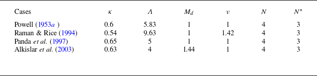
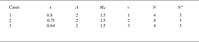
The operation conditions used in four experiments in the open literature, including the aspect ratio of the rectangular nozzle (
 $\Lambda$
), the designed Mach number of the nozzle (
 $M_d$
) and the temperature ratio (
 $\nu$
), are listed in table 1. In these experiments, the convection velocities of the instability wave were all measured. The constants
 $\kappa$
obtained from these experiments are listed in table 1. We observe that these values are different from each other, which may be due to the different measurement methods and different operation conditions employed across these experiments. In this study, these experimentally measured
 $\kappa$
are used to perform the computation, as direct experimental measurements are free from many assumptions used in linear stability analysis and are therefore expected to reflect more realistic flow physics. Note that Panda et al. (Reference Panda, Raman and Zaman1997) observed that the constant
 $\kappa$
increased as
 $M_{\textrm {i}}$
increased, from 0.6 at low
 $M_{\textrm {i}}$
to 0.7 at high
 $M_{\textrm {i}}$
. For our calculations, we use an average value of
 $0.65$
as the input.
Operation conditions used in several experiments.

In addition, the screech source region was reported to be around the fourth shock structure from experimental observations, thus we set
 $N=4$
and
 $N^*=3$
in the four cases. To calculate the shock spacing
 $s$
in (3.6) and (3.8), we use the model proposed by Tam (Reference Tam1988), where
 $s$
can be expressed by
 \begin{equation} s=2\sqrt {M_{\textrm {i}}^2-1}\left [\left (\frac {{1}}{{{W}}}\right )^2+1\right ]^{-\frac {1}{2}}. \end{equation}
Here,
 ${W}$
represent the non-dimensional height and width of the fully expanded jet flow, and
 $1/{W}$
is related to the jet aspect ratio (
 $\Lambda$
), the Mach number of the fully expanded jet flow (
 $M_{\textrm {i}}$
) and the designed Mach number (
 $M_d$
). The method to calculate
 $1/{W}$
can be found from Tam (Reference Tam1986).
The phase
 $\Phi _1$
and the phase delay
 $\Delta \Phi _2$
can be readily calculated if
 $f$
is provided. However,
 $f$
depends on
 $\Phi _1$
and
 $\Delta \Phi _2$
via (3.8). So to determine
 $\Phi _1$
and
 $\Delta \Phi _2$
in (3.8), we use an iterative scheme as follows. We first employ the operation conditions presented in table 1 and calculate the screech frequency using Powell’s original formula (1.1). Subsequently, the obtained frequency is substituted into this model to determine
 $\Phi _1$
and
 $\Delta \Phi _2$
. A new screech frequency can then be predicted using (3.8). This new frequency can be used to obtain an updated
 $\Phi _1$
and
 $\Delta \Phi _2$
. The procedures are repeated until a converged frequency is obtained. We first show the phase changes in figure 7. As can be seen, both
 $\Phi _1$
and
 $\Delta \Phi _2$
increase as the jet Mach number increases. Here,
 $\Phi _1$
increases in a nearly linear manner with respect to
 $M_{\textrm {i}}$
, while
 $\Delta \Phi _2$
varies slowly as
 $M_{\textrm {i}}$
changes, increasing from nearly
 $\pi /2$
at low Mach numbers to
 $\pi$
as
 $M_{\textrm {i}}$
increases to 1.8. It is interesting to note that
 $\Phi _1$
calculated in this model, though under different operation conditions, is consistent qualitatively to that obtained by Mancinelli et al. (Reference Mancinelli, Martini, Jaunet, Towne and Gervais2023).
Equipped with the
 $\Phi _1$
and
 $\Delta \Phi _2$
, we can calculate
 $f$
from (3.8). Comparisons among this model prediction, Powell’s model prediction and the experimental data are shown in figure 8. It can be seen that this model predictions agree well with the experimental data in figures 8(c) and 8(d), while Powell’s model predictions seem to show an overprediction compared with the experiments. Note that in figure 8(c), setting
 $\kappa =0.5$
can lead to favourable agreement between Powell’s model prediction and the experimental data, as shown by Berland et al. (Reference Berland, Bogey and Bailly2007), whereas using the convection velocity directly obtained from the experimental data leads to an overprediction. In figure 8(a), however, this model underpredicts the screech frequency, while Powell’s model prediction agrees well with the experimental data. Note that if the constant
 $\kappa$
is assumed to be
 $0.7$
, Powell’s model overpredicts the screech frequency compared with the experimental data, as shown by Tam (Reference Tam1988), while this model prediction would show good agreement with the experimental data. Whether this underprediction is due to an inaccurate
 $\kappa$
is not yet clear and therefore requires further scrutiny. In figure 8(b), both of the two models provide favourable results. Specifically, Powell’s model prediction agrees well with the experimental data when
 $M_{\textrm {i}}\lt 1.6$
, while this model prediction agrees well with the experimental data at low Mach numbers and high Mach numbers.
Overall, the model predictions show favourable agreement with experimental data (Raman & Rice Reference Raman and Rice1994; Panda et al. Reference Panda, Raman and Zaman1997; Alkislar et al. Reference Alkislar, Krothapalli and Lourenco2003), suggesting that accounting for the additional phase delay may correct the overprediction of the classical model under several operation conditions. However, uncertainty remains regarding the convection velocity of the instability waves. For a more conclusive comparison of the model’s prediction compared with previous ones, a precise and detailed examination of this convection velocity would be necessary.
Phase changes
 $\Phi _1$
and
 $\Delta \Phi _2$
at the screeching frequency. The operation conditions used in (a–d) are the same as those used by Powell (Reference Powell1953b
), Raman & Rice (Reference Raman and Rice1994), Panda et al. (Reference Panda, Raman and Zaman1997) and Alkislar et al. (Reference Alkislar, Krothapalli and Lourenco2003), respectively.

Comparison between Tam’s model prediction, this model prediction and the experimental data. The solid blue curve is calculated by Powell’s model. The dashed red line is obtained using this model. Experimental data in (a–d) are measured by Powell (Reference Powell1953b ), Raman & Rice (Reference Raman and Rice1994), Panda et al. (Reference Panda, Raman and Zaman1997) and Alkislar et al. (Reference Alkislar, Krothapalli and Lourenco2003), respectively.

In the final part of this section, we consider the thermal influence on the phase condition, which can be accounted for in two ways. A traditional model of the thermal effect is through the modification of
 $U_c$
, as shown by (2.2). This effect was previously considered by Tam et al. (Reference Tam, Seiner and J.C.1986) for circular jet flow. They found that under different temperature ratios, the screech frequency can be predicted by
 \begin{equation} f=0.67(M_{\textrm {i}}^2-1)^{-1/2}\left [1+0.7M_{\textrm {i}}\left (1+\frac {\gamma -1}{2}M_{\textrm {i}}^2\right )^{-1/2}\nu ^{1/2}\right ]^{-1}. \end{equation}
In the rectangular jet flows, a similar formula may be obtained from (3.6) and (3.9), assuming
 $N=n$
,
 ${\Delta } \phi =0$
and
 $\kappa =0.7$
, i.e.
 \begin{equation} f=0.35(M_{\textrm {i}}^2-1)^{-1/2}\left [1+0.7M_{\textrm {i}}\left (1+\frac {\gamma -1}{2}M_{\textrm {i}}^2\right )^{-1/2}\nu ^{1/2}\right ]^{-1}\left [\left (\frac {1}{{W}}\right )^2+1\right ]^{\frac {1}{2}}. \end{equation}
Operation conditions used by Gojon et al. (Reference Gojon, Gutmark and Mihaescu2019).

Note that the difference between (3.10) and (3.11) arises from the distinct values of the shock spacing in circular and rectangular jet flows, which can be predicted by Pack’s model (Pack Reference Pack1950; Tam Reference Tam1988), i.e.
 $s={\pi } \sqrt {M_{\textrm {i}}^2-1}/2.4048$
for circular nozzles while
 $s=2\sqrt {M_{\textrm {i}}^2-1}/\sqrt {{1}/{{W}^2}+1}$
for rectangular cases.
Phase delay between the upstream forcing and newly excited instability wave at the screeching frequency. The parameter
 $\kappa$
takes the value of 0.7 in the three cases and the angular frequency is calculated using (1.1).

In this model, from figure 5, we can see that the phase delay is also changed by the temperature ratios. Therefore, to predict the screech frequency more accurately, the changes in the phase delay and the convection velocity
 $U_c$
should both be accounted for. To quantitatively evaluate the thermal effects, we take three temperature ratios, i.e.
 $\nu =1$
,
 $2$
and
 $3$
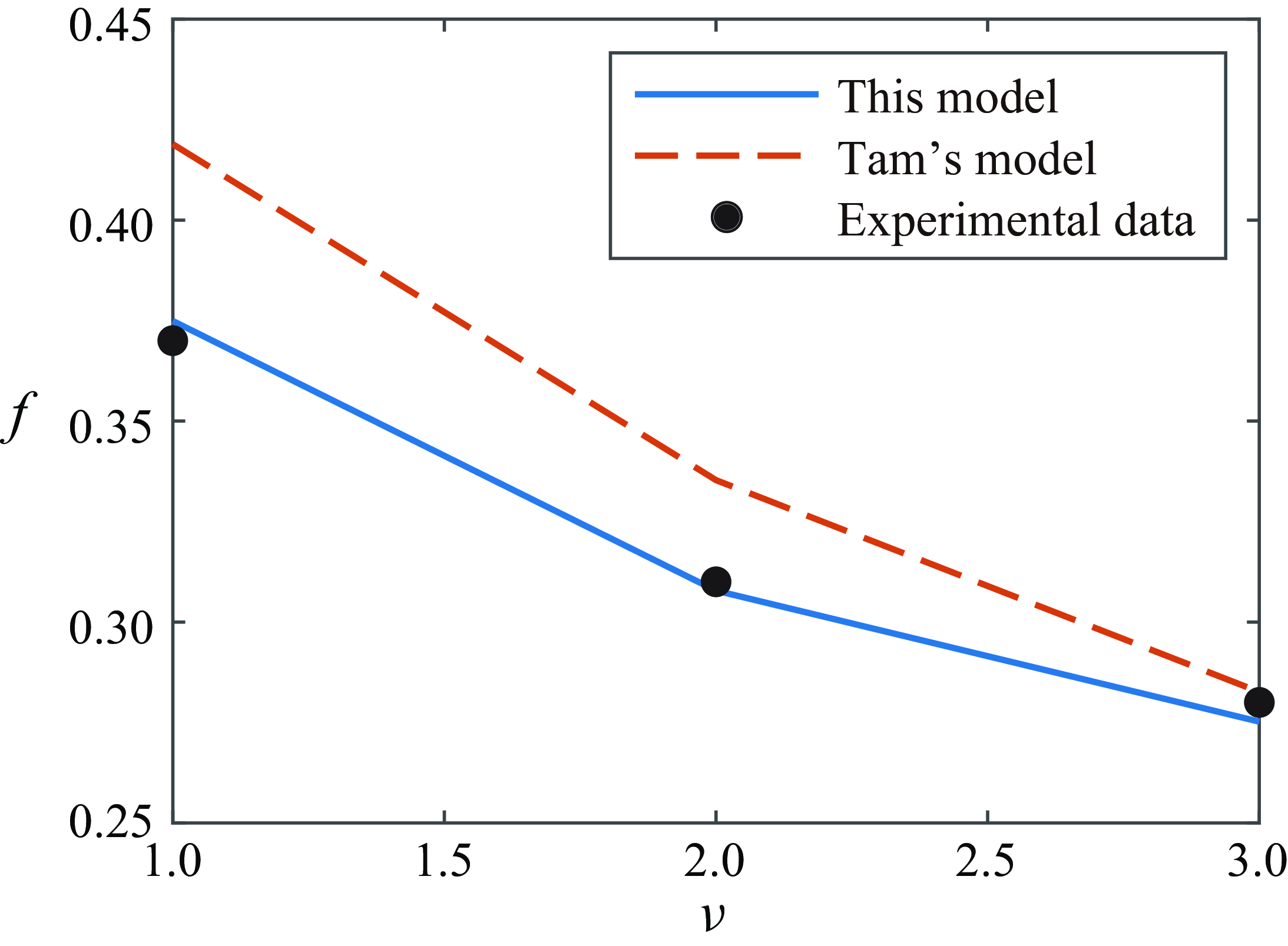
, into consideration. We calculate the transfer function at the screeching frequency under the three temperature ratios, the phase delays of which are shown in figure 9. Note that the screech frequency is calculated via (1.1) with the constant
 $\kappa =0.7$
. We can see that under the three temperature ratios, phase delays increase as the jet Mach number increases. In addition, higher jet temperatures lead to larger phase delays (
 $\Delta \Phi _2$
) across the entire range of Mach numbers, which will, according to (3.8), result in a lower frequency prediction. Note that this appears to contradict figure 5, but this apparent contradiction results from the fact that we are considering the phase delay at the screech frequency for each
 $M_{\textrm {i}}$
and
 $\nu$
, whereas figure 5 considers the phase delay for a given
 $M_{\textrm {i}}$
at the same frequency.
To quantitatively validate (3.8), we use the data from Gojon et al. (Reference Gojon, Gutmark and Mihaescu2019), where overexpanded jet flows under different temperature conditions were simulated using LES. The convection velocity of the instability waves was numerically obtained. They compared the frequency prediction from Tam’s model (Tam Reference Tam1988) to the reported experimental results (Mora et al. Reference Mora, Baier, Gutmark and Kailasanath2016). An overestimation of approximately
 $10\,\%$
compared with the experimental data was reported (Gojon et al. Reference Gojon, Gutmark and Mihaescu2019). This overprediction may be rectified if the calculated
 $\Delta \Phi _2$
is considered. To obtain the screech frequency prediction, we employ the data of the convection velocity from Gojon et al. (Reference Gojon, Gutmark and Mihaescu2019) and evaluate (3.8) under the three different temperature ratios. The operation conditions are the same as those used by Gojon et al. (Reference Gojon, Gutmark and Mihaescu2019) and are listed in table 2. The comparison is shown in figure 10. These results indicate that if the additional phase delay is included, the predicted screech frequency agrees much better with the numerical simulation. Specifically, the overprediction from the classical model is rectified when the phase delay is considered.
Assumptions employed by the existing models used in this paper.

Comparison of Tam’s model prediction, this model prediction and the experimental data (Gojon et al. Reference Gojon, Gutmark and Mihaescu2019). The dashed red curve is calculated by Tam’s model. The solid blue line is obtained using this model. Filled circle points represent experimental data from Gojon et al. (Reference Gojon, Gutmark and Mihaescu2019).

4. Dicussion and conclusion
This paper investigates the jet receptivity occurring at the nozzle lip within the screech feedback loop. The scattered field due to the upstream-propagating acoustic waves is derived using the Wiener–Hopf method, with the kernel decomposed through matched asymptotic expansions. To determine the newly 3 triggered instability wave, we impose the unsteady Kutta condition by eliminating the emerging singularities in the scattered field. This results in a dispersion relation that governs the newly excited instability waves. The transfer function between the newly excited instability waves and the upstream forcing is subsequently obtained. The amplitude and phase of the transfer function are then discussed in detail.
The result shows that the scattering efficiency
 $|H|$
displays multiple peaks and valleys as the frequency increases. In addition, it is less than
 $5\,\%$
under each operation condition that we consider. Moreover, the phase delay between the instability wave and the upstream forcing generally decreases as the frequency increases. Regarding the thermal influence on the transfer function, it is found that the scattering efficiency decreases slightly as the temperature ratio increases from 1 to 3, while higher jet temperatures can lead to lower phase delays at low frequencies but result in slightly higher phase delays at high frequencies.
Including this additional phase delay, we invoke the phase condition to predict the screech frequency. The results demonstrate favourable agreement with the experimental data for cold supersonic jets. In particular, the overprediction of screech frequencies from classical models appears to be rectified using the present model, except for the case of Powell’s measurement. However, given the remaining uncertainties in the evaluations of
 $\kappa$
, a precise and detailed examination of this convection velocity would be necessary for a more conclusive comparison. In addition, we examine the effects of the temperature ratio on the screech frequency by including the additional phase delay, the result of which shows that the screech frequency prediction improves significantly.
When validating the model, we compare our predictions with measured screech frequencies from experiments. It is important to note that the models proposed by Powell (Reference Powell1953a ) and Tam (Reference Tam1988), although not accounting for phase delays in the feedback loop, may also yield favourable predictions if the parameters exhibiting large uncertainty, such as the shock spacing and the convection velocity of the instability waves, are chosen carefully. However, in physics, we would expect such a phase delay to exist between the upstream forcing and the newly excited instability wave. The transfer function derived in this paper explicitly accounts for this, thereby eliminating one piece of empiricism and adding further insights into the receptivity process. We therefore believe that this model helps to advance our understanding of receptivity and represents a crucial step towards developing a comprehensive screech model.
It is important to note that while this model predicts the screech frequency using the phase condition, the gain condition remains crucial for determining whether the jet screech can occur or not. However, in addition to the amplitude of the transfer function during receptivity, the total gain of the instability wave as it propagates downstream would also be required. Obtaining the latter is challenging and may be a focus of our future study. Note also that the scattering efficiency obtained from the transfer function can also be examined in detail, which is not extensively explored in this paper due to a lack of direct experimental or numerical validation in the current literature.
Lastly, we acknowledge the importance of developing a similar model for round jets, where the receptivity process plays a critical role in determining both screech amplitude and mode staging phenomena. While our current work focuses on a two-dimensional model, we believe it offers valuable insights into the receptivity process and serves as a useful first step towards developing a comprehensive screech model applicable to all types of jets.
Acknowledgments
B.L. gratefully acknowledges Y. Ye for his valuable advice on numerical integration.
Funding
The authors extend their gratitude to the financial support from Laoshan Laboratory (grant number LSKJ202202000), as well as to the National Natural Science Foundation of China (NSFC) for support (grant number 12472263).
Declaration of interests
The authors report no conflict of interest.
Appendix A
Following the procedure of Ferrari’s formula, zeros of the polynomial can be determined. Define a parameter
 $y_a$
as
 \begin{equation} y_a=\sqrt [3]{c_2+\sqrt {c_3}}+\sqrt [3]{c_2-\sqrt {c_3}}, \end{equation}
where
 \begin{gather} c_2=a_1^2/2, \end{gather}
 \begin{gather} c_3=c_2^2-64a_0^3/27. \end{gather}
The zeros
 $q_1,q_5,q_2,q_6$
take the following forms:
 \begin{equation} q_{1,5}=-\frac {1}{2}\sqrt {y_a}\pm \frac {1}{2}\sqrt {-y_a+\frac {2a_1}{\sqrt {y_a}} }, \end{equation}
 \begin{equation} q_{2,6}=\frac {1}{2}\sqrt {y_a}\pm \frac {1}{2}\sqrt {-y_a-\frac {2a_1}{\sqrt {y_a}} }. \end{equation}
Zeros
 $q_3, q_7, q_4, q_8$
take similar forms, i.e.
 \begin{equation} q_{3,7}=-\frac {1}{2}\sqrt {y_a}\pm \frac {1}{2}\sqrt {-y_a-\frac {2a_1}{\sqrt {y_a}} }, \end{equation}
 \begin{equation} q_{4,8}=\frac {1}{2}\sqrt {y_a}\pm \frac {1}{2}\sqrt {-y_a+\frac {2a_1}{\sqrt {y_a}} }. \end{equation}
It can be shown, by some algebra, that when the angular frequency
 $\omega \gt 0.05$
and
 $1\lt M_{\textrm {i}}\lt 2$
,
 $c_3\gt 0$
and
 $c_3^{*}\gt 0$
. In addition,
 $y_a^{*}$
can be shown to be a real number.
Comparison between the wavenumber numerically obtained by the dispersion relation and that calculated through the asymptotic expansions. The temperature ratio
 $\nu$
equals (a) 3 and (b) 5.

With a negative real part and a positive imaginary part,
 $q_3 S^{4/3}$
(
 $S$
is defined in § 2.2) corresponds to the wavenumber of the jet instability of the sinuous mode, which is defined as
 $\mathcal {K}$
in (2.63). The original polynomial
 $R(q)$
has four zeros denoted as
 $q_{2,6}$
(in the right half-plane
 $\textrm {Re}(q)\gt 0$
) and
 $q_{3,7}$
(in the left half-plane
 $\textrm {Re}(q)\lt 0$
). The additional zeros are due to the increase in the polynomial order.
To further validate the decomposition, we present the additional comparison between the wavenumber numerically obtained by the dispersion relation and that calculated through the asymptotic expansions using different temperature ratios. As shown in figure 11, we see that for the heated jets under consideration (
 $\nu =3$
or
 $\nu =5$
), the agreement between the two wavenumbers remains satisfactory as
 $M_{\textrm {i}}\gt 1.2$
.
Within the typical range of screech (
 $1.1\lt M_{\textrm {i}}\lt 1.8$
), we can show that
 $S \lesssim 0.3$
and
 $S^{1/4}$
is of the order of 1, enabling the expansion shown in (2.42). In heated jets, such approximation is more accurate and we do not present them for brevity. Therefore, we can conclude that under the typical operation conditions supporting screech, i.e.
 $1.1\lt M_{\textrm {i}}\lt 1.8$
and
 $\nu \geqslant 1$
, the matched asymptotic expansion presented in the manuscript serves as a good approximation. Furthermore, the compact form of
 $K_+ (k)$
in (2.61) can be reliably used.
Appendix B
We first provide the detailed derivation from (2.51) to (2.52). Subtracting the left-hand side and right-hand side of (2.51) by
 $\sum _{n=1}^8 1/2(q-q_n)$
, the left-hand side part can be directly written as
 \begin{align} \frac {\textrm {d}}{\textrm {d} q} \ln \left (\frac {R_{+}(q)}{\prod _{n=5}^8\left (q-q_n\right )^{1/2}}\right )+\frac {\textrm {d}}{\textrm {d} q} \ln \left (\frac {R_{-}(q)}{\prod _{n=1}^4\left (q-q_n\right )^{1/2}}\right ). \end{align}
Using partial fraction decomposition, we can assume that the right-hand side part takes the following form:
 \begin{equation} \frac {(4q^3+a_1 |q|/q)(q^4-a_1|q|+a_0)}{(q^4+a_0)^2-a_1^2q^2}-\sum _{n=1}^8\frac {1}{2(q-q_n)}=\sum _{n=1}^8 \xi _n \frac {1}{q-q_n}+\xi _9 \frac {1}{q-q_9}, \end{equation}
where
 $q_9=0$
. The undetermined coefficient
 $\xi _n$
can be calculated by multiplying the left-hand and right-hand side of (B2) by the corresponding
 $q-q_n$
and letting
 $q=q_n$
subsequently.
In what follows, we provide the detailed derivation from (2.52) to (2.58). Using the addictive decomposition (2.55) and the identity (2.54), the right-hand side of (2.52) can be rewritten as
 \begin{equation} \sum _{n=1}^9\xi _n\frac {q_n+\dfrac {\textrm {i}q_n}{\pi }\ln _+ q-\dfrac {\textrm {i}q_n}{\pi }\ln _- q}{q-q_n}, \end{equation}
which can be reorganised as
 \begin{equation} \sum _{n=1}^9\xi _n\frac {\left (q_n+\dfrac {\textrm {i}q_n}{\pi }\ln _+ q_n-\dfrac {\textrm {i}q_n}{\pi }\ln _- -q_n\right )+\dfrac {\textrm {i}q_n}{\pi }\ln _+ q/q_n-\dfrac {\textrm {i}q_n}{\pi }\ln _- -q/q_n}{q-q_n}. \end{equation}
Using the identity (2.57), we can reduce (B4) to
 \begin{align} \sum _{n=1}^9\xi _n\frac {\dfrac {\textrm {i}q_n}{\pi }\ln _+ q/q_n}{q-q_n}-\sum _{n=1}^9\xi _n\frac {\dfrac {\textrm {i}q_n}{\pi }\ln _- q/q_n}{q-q_n}-\sum _{n=1}^9\xi _n \frac {q_n}{q-q_n}. \end{align}
Considering that
 $R_+ (q)$
and
 $R_- (q)$
should be analytic and non-zero in the upper and lower half-planes, respectively, we can properly write
 $R_+ (q)$
as the form shown in (2.58).
Appendix C
The detailed expression for the coeffient
 $D_{\textrm {o}}(\lambda )$
takes the form
 \begin{align} D_{\textrm {o}}(\lambda ) &= \frac {A\textrm {e}^{\frac {1}{2}\gamma _{\textrm {o}}}}{2U\eta M_{\textrm {o}}^{2}}\left [\gamma _{\textrm {i}}\coth ({\gamma _{\textrm {i}}}/{2})\mathcal {I}_{c}\sin (\pm a\beta /2)\beta \left [\omega \left (2k_{1}m_{\textrm {i}}\cosh (m_{\textrm {i}}/2)\pm m_{\textrm {o}}\textrm {e}^{\mp \frac {1}{2}m_{\textrm {o}}}\right )\nonumber\vphantom{\frac {M_{\textrm {i}}^{2}}{M_{\textrm {o}}^{2}}a^{2}}\right.\right.\\ &\quad\left. - \frac {1}{\omega }m_{\textrm {o}}\frac {M_{\textrm {i}}^{2}}{M_{\textrm {o}}^{2}}a^{2}\textrm {e}^{-\frac {1}{2}m_{\textrm {o}}}\right ]+M_{\textrm {i}}^{2}(\omega +\lambda )\left ( \gamma _{\textrm {i}}\coth ({\gamma _{\textrm {i}}}/{2})\frac {2U}{A}G^{p}(\pm 1/2)\vphantom{\frac {M_{\textrm {i}}^{2}}{M_{\textrm {o}}^{2}}a^{2}}\nonumber\right.\\ &\quad\, - \frac {2U}{A}{G^{p}}^{\prime }(\pm 1/2)-i a \beta \mathcal {I}_{s}[b_{1}\sin (\pm a\beta /2)+c\beta \cos (a\beta /2 )]\nonumber\\ &\!\quad \left.\left. \vphantom{\frac {M_{\textrm {i}}^{2}}{M_{\textrm {o}}^{2}}a^{2}} -\mathcal {I}_{c}[b_{2}\sin (\pm a\beta /2 )-c\alpha \cos (a\beta /2 )]\right )\right ], \end{align}
where the parameters are associated with shock and instability waves, and can be found in our previous work (Li & Lyu Reference Li and Lyu2023). This coefficient
 $D_o (\lambda )$
influences the determination of the decay rate
 $\epsilon$
, which can be determined by calculating the upstream-propagating acoustic wave just outside the jet flow. The details of the calculation are presented in what follows.
To calculate the acoustic wave propagating just outside the jet flow, i.e.
 $\phi _{\textrm {in}}(x,1/2)$
, it is convenient to deform the integration path in (2.3) along the branch cut of
 $\gamma _1$
at
 $k=\omega M_{\textrm {o}}$
. In this way, the difference in the value of
 $D_{\textrm {o}}(\lambda )$
on two different sides of the branch cut only comes from
 $\gamma _{+}$
. Thus,
 $\phi _{\textrm {in}}(x,1/2)$
can be expressed as
 \begin{equation} \phi _{\textrm {in}}(x,1/2)=\frac {\textrm {i}}{2\pi }\textrm {e}^{-\textrm {i}M_{\textrm {o}}\omega x }\int _{0}^{+\infty }[D_{{\textrm {o}}}^{*}(M_{\textrm {o}}\omega +\textrm {e}^{\textrm {i}\pi /2}\zeta )-D_{{\textrm {o}}}^{*}(M_{\textrm {o}}\omega +\textrm {e}^{\textrm {i}3\pi /2}\zeta )]\textrm {e}^{\zeta x}\textrm {d}\zeta , \end{equation}
where
 $D^{*}(\zeta )=D_{\textrm {o}}(\zeta )/\textrm {exp}(\gamma _{+}/2)$
and
 $\lambda =\omega M_{\textrm {o}}+\textrm {i}\zeta$
. It is straightforward to see that only
 $\eta (\lambda )$
contains
 $\gamma _{+}$
(the definition of
 $\eta (\lambda )$
can be found from Li & Lyu (Reference Li and Lyu2023)). We can define a new function
 $E_{{\textrm {o}}}(\zeta )$
as follows:
 \begin{equation} E_{{\textrm {o}}}(\zeta )=D_{{\textrm {o}}}^{*}(\zeta )\eta (\zeta ). \end{equation}
Then,
 $\phi _{\textrm {in}}(x,1/2)$
can be reorganised as
 \begin{equation} \phi _{\textrm {in}}(x,1/2)=\frac {-\textrm {i}}{\pi }\textrm {e}^{-\textrm {i}M_{\textrm {o}}\omega x }\int _{0}^{+\infty }E_{{\textrm {o}}}(\zeta )\frac {\omega ^3\coth (\gamma _{-}/2)\gamma _{-}}{\omega ^{4}\coth ^{2}(\gamma _{-}/2)\gamma _{-}^2-(\omega +\lambda )^{4}{\varDelta }^{2}(\zeta )\frac {M_{\textrm {i}}^4}{M_{\textrm {o}}^4}} \textrm {e}^{\zeta x} \textrm {d}\zeta , \end{equation}
where
 \begin{equation} {\varDelta }(\zeta )=\sqrt {\textrm {e}^{\pi \textrm {i}/2 }\zeta (\textrm {i}\zeta +2M_{\textrm {o}}\omega )}. \end{equation}
Letting
 $\zeta ^{*}=\zeta -\textrm {i}M_{\textrm {o}}\omega =-\textrm {i}\lambda$
and performing a coordinate transformation from
 $x=0$
to
 $x=-h$
, we can write the function
 $\mathcal {G}(\lambda )$
in (2.69) as
 \begin{equation} \mathcal {G}(\zeta ^{*})=\frac {-\textrm {i}}{\pi }E_{\textrm {o}}(\zeta ^{*})\frac {\omega ^3\coth (\gamma _{-}/2)\gamma _{-}}{\omega ^{4}\coth ^{2}(\gamma _{-}/2)\gamma _{-}^2-(\omega +\lambda )^{4}{\varDelta }^{2}(\zeta ^{*})\frac {M_{\textrm {i}}^4}{M_{\textrm {o}}^4}} \textrm {e}^{-\zeta ^{*}h}. \end{equation}
It can be proved that as
 $\zeta ^{*}\rightarrow 0$
,
 $\mathcal {G}(\zeta ^{*})$
takes the following asymptotic forms:
 \begin{equation} \mathcal {G}(\zeta ^{*})=\mathcal {G}(0)+\mathcal {C}\zeta ^{*}+O(\zeta ^{*^2}). \end{equation}
Here,
 $\mathcal {G}(0)$
is what we aim to find to determine
 $\epsilon$
in (2.71), which can be calculated by letting
 $\zeta ^*=0$
in (C6), while
 $\mathcal {C}$
, a coefficient of order
 $O(1)$
, is not presented here for clarity.
In what follows, we provide a proof of (2.70), which is essential to uniquely determine
 $\epsilon$
. The approximated form of the upstream forcing can be written as
 \begin{equation} G\textrm {e}^{\epsilon x}, \end{equation}
while without an approximation, the forcing reads
 \begin{equation} \int _{0}^{\infty } \mathcal {G}(\zeta ^{*})\textrm {exp}(\zeta ^{*} x) \textrm {d}\zeta ^{*}. \end{equation}
These two expressions should be virtually the same when
 $x\lt 0$
. Multiplying (C8) and (C9) by
 $\textrm {e}^{\textrm {i}kx}/K_+(k)$
, and integrating each expression with respect to
 $x$
from
 $-\infty$
to
 $\infty$
, we can find that (C8) and (C9) can be respectively evaluated as
 \begin{equation} \frac {2\pi G\delta (\textrm {i}k+\epsilon )}{K_+(k)} \quad \textrm {and} \quad \frac {2\pi \int _{0}^{\infty } \mathcal {G}(\zeta ^{*})\delta (\textrm {i}k+\zeta ^*) \textrm {d}\zeta ^{*}}{K_+(k)}. \end{equation}
Subsequently, integrating each expression with respect to
 $k$
from
 $-\infty$
to
 $\infty$
yields (2.70).
Appendix D
This paper builds on the vortex sheet model together with a prescribed forcing from the shock-instability interaction (SII) model (Li & Lyu Reference Li and Lyu2023). It is then validated against numerical and experimental data using shock spacing calculated from Pack’s model (Pack Reference Pack1950) and Tam’s model (Tam Reference Tam1988). The assumptions underlying each of these models are summarised in table 3. Note that all the models are formulated within the framework of linear analysis, with the initial base flow assumed to be inviscid both within and outside the jet.
The vortex sheet model has been widely used in linear stability analysis (Batchelor & Gill Reference Batchelor and Gill1962; Crighton Reference Crighton1973) and jet aeroacoustics modelling (Crighton Reference Crighton1972; Tam & Hu Reference Tam and Hu1989; Crighton & Huerre Reference Crighton and Huerre1990; Crighton Reference Crighton1992). Models derived from the vortex sheet framework can effectively reveal some fundamental mechanisms underlying physical phenomena. Pack’s model provides remarkably accurate predictions of shock spacing, even when the jet is not slightly off-design (Li & Gao Reference Li and Gao2010). In addition, it accurately approximates pressure perturbations within a single shock cell (Norum & Seiner Reference Norum and Seiner1982). Tam’s model satisfactorily predicts shock spacing in slightly off-design jets, which was supported by both experimental results (Tam Reference Tam1988) and numerical simulations (Jeun et al. Reference Jeun, Karnam, Wu, Lele, Baier and Gutmark2022). The shock-instability interaction model was validated in the authors’ previous work (Li & Lyu Reference Li and Lyu2023) by comparing with numerical simulations (Wu et al. Reference Wu, Lele and Jeun2020) and a wide variety of experimental data (Ponton et al. Reference Ponton, Manning and Seiner1986).
The development of the present transfer function relies on several assumptions, which are summarised in table 4 to improve clarity. As can be seen in table 4, they are categorised into three relevant domains, i.e. geometrical, mathematical and physical assumptions.
Assumptions employed when deriving the present model.