Electrocaloric effects
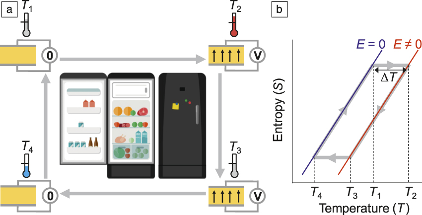
Electrocaloric (EC) effectsReference Moya, Kar-Narayan and Mathur1–Reference Kutnjak, Rožič, Pirc and Webster8 are reversible thermal changes that arise in electrically polarizable materials due to changes in the electric field, ΔE. An example of how EC effects can be exploited in cooling cycles for heat pumps is shown in Figure 1.Reference Brown9,Reference Crossley, Nair, Whatmore, Moya and Mathur10 EC effects are normally parameterized as adiabatic changes in temperature, ΔT, or isothermal changes in entropy, ΔS, which can be expressedReference Moya, Kar-Narayan and Mathur1 using equilibrium thermodynamics as:
 $$\Delta T{\rm{\ }} = - \int_{{E_{\rm{i}}}}^{{E_{\rm{f}}}} {{T \over c}{{\left( {{{\partial P} \over {\partial T}}} \right)}_E}{\rm{d}}E} and \Delta S{\rm{\ }} = \int_{{E_{\rm{i}}}}^{{E_{\rm{f}}}} {{{\left( {{{\partial P} \over {\partial T}}} \right)}_E}{\rm{d}}E}$$,
where P is the electrical polarization, c is the specific heat capacity, E i is the initial applied field, and E f is the final applied field. EC effects are expected to be large near ferroelectric phase transitions,Reference Moya, Kar-Narayan and Mathur1 where the electrical polarization varies strongly with temperature.
Electrocaloric (EC) cooling cycle. (a) Schematic based on a single layer capacitor. (b) Plot of entropy, S, versus temperature, T. (a–b) At starting temperature, T 1, the fast application of a voltage (corresponding to electric field, E) adiabatically polarizes the unpolarized active material, whose temperature is increased to T 2. Heat is then dumped by relative motion along the length of a (fluid) regenerator,Reference Brown9 such that the temperature of the material is reduced to T 3. Fast removal of the electric field then adiabatically depolarizes the active material, whose temperature is further reduced to T 4. Finally, heat is absorbed from the regenerator by relative motion in the opposite direction along the regenerator, such that the temperature of the material is increased back to T 1. This completes the cycle. We assume that the EC effect does not vary with starting temperature, such that no net heat is exchanged between the material and the regenerator (true regenerationReference Crossley, Nair, Whatmore, Moya and Mathur10), as seen in (b). In (a), we also assume that the active material is a displacive ceramic ferroelectric above the Curie temperature, such that no dipoles are present at zero field.

For several decades, EC effects in ferroelectric oxides and polymers have been investigatedReference Moya, Kar-Narayan and Mathur1–Reference Kutnjak, Rožič, Pirc and Webster8 using thinned bulk samples and films of various thicknesses. The EC effects tend to be small in thinned bulk materials, as the resulting samples are too thick to support very large electric fields without breakdown.Reference Moya, Kar-Narayan and Mathur1,Reference Valant5 In contrast, thin films can support large electric fields and therefore show larger EC effects. EC thin films, however, can only pump a small amount of heat, and they are typically attached to substrates that constitute thermal anchors.
Multilayer capacitors (MLCs) based on EC materials do not suffer from any of the above problems, because they comprise many electrode films.Reference Kar-Narayan and Mathur11 Moreover, the metallic electrodes can be exploited to help transfer heat between the thermally insulating EC layersReference Kar-Narayan and Mathur11 and the rest of the thermal pathway in a given cooling device. Here, we describe MLCs based on good EC materials, and discuss their use and potential in EC cooling devices.
MLCs
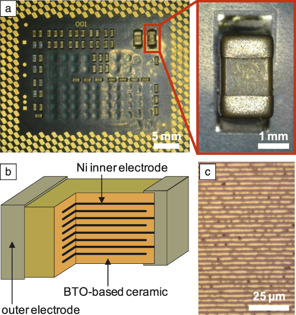
A capacitor is an electronic device that stores electrical charge using two closely spaced metallic plates separated by an electrically polarizable medium (or free space). Over the last three decades, trends toward miniaturization, high performance, and low power consumption have dominated the ceramic capacitor industry, motivated to a large extent by the rise of mobile phones and compact computers. A MLC comprises many electrically polarizable layers that lie electrically in parallel due to interdigitated inner electrodes (Figure 2). The large resulting capacitance between the two terminals (outer electrodes) permits a large amount of charge to be stored in a small volume.
Multilayer capacitors (MLCs) as existing electronic components. (a) Rear view of an Intel Xeon E3 processor, showing an assembly of MLCs of different sizes that provide protection from current spikes by providing a charge reservoir. (b) Schematic of one such MLC with two outer electrodes (terminals). For the MLC highlighted in (a), there are 200 inner electrodes of 2-µm-thick Ni that address 2-µm-thick layers of doped BaTiO3 (BTO). (c) Optical micrograph of a MLC in cross section.

MLCs based on micron-thick layers of high-permittivity ceramic oxides are mass-produced worldwide via the following fabrication process, which is used to produce billions of units each year.12 (1) Powdered oxides, binders, and solvents are mixed to form a slurry. (2) The slurry is tape cast to form green ceramic sheets. (3) Metallic electrodes are screen printed onto the green ceramic sheets. (4) The green ceramic sheets with electrodes are stacked, laminated, and cut to produce individual multilayer structures. (5) The multilayer structures are fired in a furnace. (6) The two ends of the multilayer structures are dipped into a metallic ink based on Cu to metallize the two terminals, and then the structure is fired again. (7) The two terminals are electroplated with a layer of Ni as a diffusion barrier, and then a layer of Sn to facilitate soldering.
Commercial MLCs are broadly divided into two types, depending on the selection of the active material and the application. MLCs based on paraelectric materials such as TiO2 and CaZrO3 provide temperature-independent capacitances that are small,Reference Kishi, Mizuno and Chazono13 whereas multilayer capacitors based on doped ferroelectric materials such as BaTiO3 provide large capacitances that vary relatively strongly with temperature and field.Reference Kishi, Mizuno and Chazono13 The latter are normally not suitable for power electronics because of this variability, and instead, the large magnitude is widely exploited for decoupling capacitors, which suppress current spikes in microelectronics (Figure 2). Separately, this latter type of MLC also represents a highly desirable EC module, as described next.
EC performance of MLCs
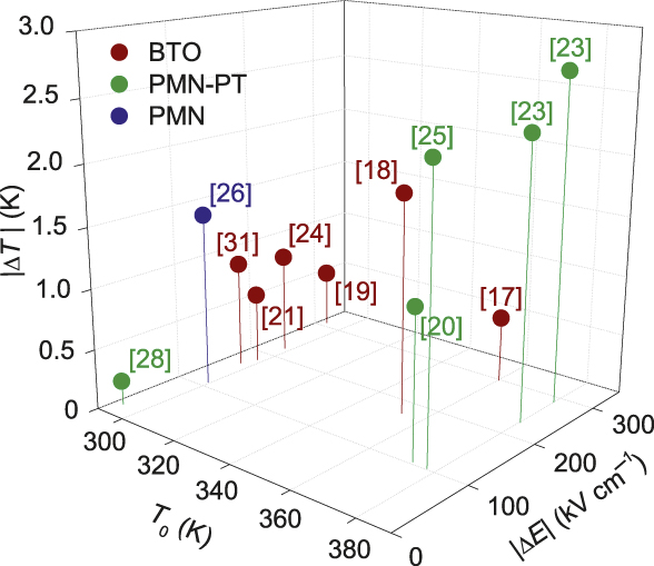
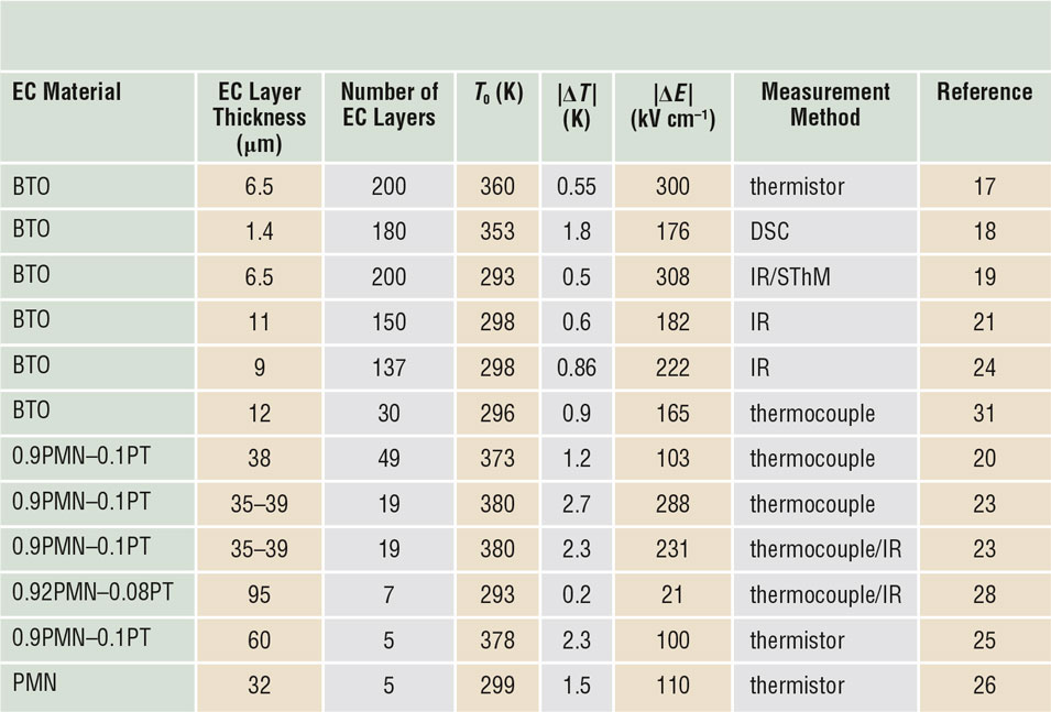
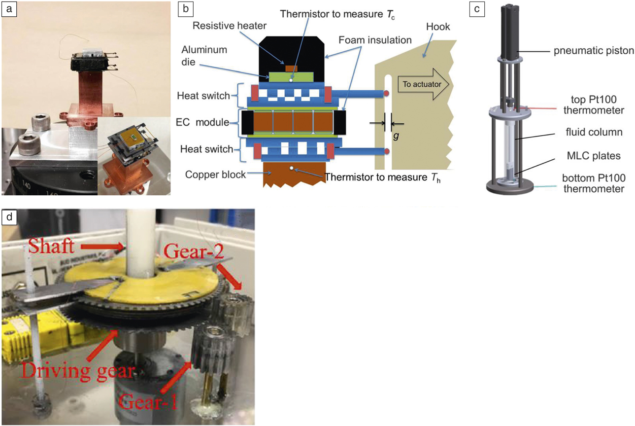
The MLC geometry was used three decades ago in order to directly measure changes in the temperature of thin EC layers.Reference Lawless and Clark14 MLCs were only later suggested as useful devices for EC cooling,Reference Mischenko and Mathur15 leading to studies based on a limited range of active materials, namely three ferroelectric oxides (based on BaTiO3, PbMg1/3Nb2/3O3-PbTiO3, and PbMg1/3Nb2/3O3), and one ferroelectric polymer (poly(vinylidene fluoride-trifluoroethylene)).Reference Gu, Qian, Li, Craven, Zhu, Cheng, Yao and Zhang16 Oxide MLCsReference Kar-Narayan and Mathur17–Reference Fulanović, Drnovšek, Uršič, Vrabelj, Kuščer, Makarovič, Bobnar, Kutnjak and Malič26 show adiabatic temperature changes of |ΔT| < 1 K near room temperature, and |ΔT| < 2.5 K at high temperatures (Figure 3, Table I). This has been sufficient for the development of five EC cooling devices,Reference Jia and Ju27–Reference Zhang, Qian, Gu, Hou and Zhang31 some of which are shown in Figure 4.
Electrocaloric (EC) effects in multilayer capacitors (MLCs). Peak values of EC temperature change |ΔT| arise due to the maximum changes of field |ΔE| at optimum starting temperatures T 0. The active layers comprise doped BaTiO3 (BTO), PbMg1/3Nb2/3O3-PbTiO3 (PMN-PT), and PbMg1/3Nb2/3O3 (PMN).

Adiabatic electrocaloric temperature change |ΔT| due to the maximum changes in field |ΔE| at optimum starting temperature T 0, for selected multilayer capacitors.

The active layers comprise doped BaTiO3 (BTO), PbMg1/3Nb2/3O3-PbTiO3 (PMN-PT), and PbMg1/3Nb2/3O3 (PMN). Note: EC, electrocaloric; DSC, differential scanning calorimetry; IR, infrared thermometry; SThM, scanning thermal microscopy.
Recent electrocaloric (EC) cooling devices based on multilayer capacitors (MLCs) of doped BaTiO3 (BTO). (a) Two silicon heat switches sandwich an EC module of 20 commercially manufactured MLCs, as shown Schematically in (b). For the unloaded device, the temperature difference T h – T c between hot temperature T h and cold temperature T c was 0.3 K. (c) An EC module of 150 commercially manufactured MLCs was translated along a regenerative fluid column. The temperature difference of the unloaded device was 0.13 K, as measured between the top and bottom of the regenerator. (d) The yellow EC module, which comprises a ring of 12 bespoke MLCs, was rotated in the opposite direction to an equivalent module lying underneath (not visible). The temperature difference of the unloaded device was 2 K, as measured between aluminum plates at the top and bottom (the two plates seen at the top are not labeled). Reprinted with permission from Reference Wang, Smullin, Sheridan, Wang, Eldershaw and SchwartzReferences 29–Reference Zhang, Qian, Gu, Hou and Zhang31. © 2015, 2016, and 2017 AIP Publishing.

Outlook
Further study of MLCs that show EC effects is now timely given the growing number of EC cooling devices that are being developed worldwide, and improvements in performance could lead to applications. The key goal is to increase the adiabatic temperature change that can be driven over a range of temperatures that lie near room temperature, most naturally by using better EC materials. Improvements in the fabrication process and MLC structure would also be important if they increase the breakdown field, permitting larger fields to drive larger EC effects. For example, MLC structure can be optimized via finite element analysis in order to maximize heat exchange via the terminals and also the faces. Once these improvements have been made, it will then be important to ensure resistance to fatigue during operation (e.g., by avoiding microcracksReference Fulanović, Drnovšek, Uršič, Vrabelj, Kuščer, Makarovič, Bobnar, Kutnjak and Malič26) and occasionally reversing the polarity of the applied field.Reference Weyland, Eisele, Steiner, Frömling, Rossetti, Rödel and Novak32 MLCs for EC applications therefore represent a good challenge for materials scientists, and we look forward to the forthcoming developments as the area matures.
Acknowledgments
This work was supported by the ERC Starting Grant No. 680032. X.M. is grateful for support from The Royal Society. E.D. thanks the Luxembourg National Research Fund (FNR) that supported this work through COFERMAT Grant No. FNR/P12/4853155/Kreisel.

Xavier Moya is a Royal Society University Research Fellow in the Department of Materials Science at the University of Cambridge, UK. He received his BSc degree in 2003, and his PhD degree in 2008, both in physics, from the University of Barcelona. His research focuses on magnetocaloric materials, electrocaloric materials, and mechanocaloric materials for cooling applications. He has been a Fellow of Churchill College, Cambridge, since 2014. He was awarded the Ramon Margalef Prize in 2009, the Spanish Royal Society of Physics Young Researcher in Experimental Physics Prize in 2015, and the Society of Spanish Researchers in the UK Emerging Talent Award in 2017. Moya can be reached by email at xm212@cam.ac.uk.

Emmanuel Defay leads the Ferroic Materials for Transducers Group at the Luxembourg Institute of Science and Technology. He obtained his MS degree in engineering in 1994 from ENSMM Besançon, France, his PhD degree in physics in 1999 from Institut National des Sciences Appliquées, France, and his Habilitation degree in 2007 from Institut National Polytechnique de Grenoble, France. He worked at CEA LETI, France, from 2000 to 2014, on the integration of piezoelectric materials for microsystems. He studied electrocalorics from 2010 to 2012 as a visiting scholar at the University of Cambridge, UK. His current research interests include piezoelectrics and electrocalorics. Defay can be reached by email at emmanuel.defay@list.lu.

Neil D. Mathur has been with the Department of Materials Science at the University of Cambridge, UK, since 1996. He became a research fellow funded by The Royal Society in 1999, was hired to the faculty in 2005, and became professor of materials physics in 2013. He previously studied physics at the University of Cambridge, where he received his BA degree in natural sciences, and his PhD degree on magnetically mediated superconductivity. His current research includes the physics of materials and systems with notable electrical and magnetic properties, namely electrocaloric materials, magnetoelectric heterostructures, and spintronic devices. He was elected a Fellow of the American Physical Society in 2012, and was awarded the Rosenhain Medal and Prize by the Institute of Materials, Minerals and Mining in 2009. Mathur can be reached by email at ndm12@cam.ac.uk.

Sakyo Hirose is a principal researcher at Murata Manufacturing Co., Ltd., Japan. He received his BE and ME degrees from the Tokyo Institute of Technology, Japan. He joined Murata as a researcher in 2000. He received his PhD degree on grain-boundary engineering in electroceramics from Osaka University, Japan, in 2012. His current research focuses on electric-field-driven devices for future electronics, particularly for resistive-switching memories, magnetoelectric devices, and electrocaloric devices. Hirose can be reached by email at h_sakyo@murata.com.