


1. INTRODUCTION
In recent years the field of laser–plasma interaction has been attracting the attention of physicists due to its new potential applications in science and technology. Utilizing a laser (for the production of ultra-short and high-intensity laser pulses) and the ability of plasma (as an appropriate tool for linear and nonlinear interaction of electromagnetic fields), we can study many complex systems and phenomena for the sake of many practical purposes. One of the most prominent applications in this field is the use of laser–plasma interaction for the acceleration of charged particles (electrons and ions), that is., laser–plasma accelerators (Flippo et al., Reference Flippo, Hegelich, Albright, Yin, Gautier, Letzring, Schollmeier, Schreiber, Schulze and Fernandez2007; Esarey et al., Reference Esarey, Schroeder and Leemans2009; Daido et al., Reference Daido, Nishiuchi and Pirozhkov2012; Macchi et al., Reference Macchi, Borghesi and Passoni2013). Investigation of different mechanisms of electron and ion acceleration in this approach can be attractive and useful. One of the most prestigious and most practical mechanisms of acceleration in laser-plasma accelerators, is known as radiation pressure acceleration (RPA) mechanism in which access to high-quality ion beam energies comparable with conventional (Classical and traditional) accelerators has become possible (Macchi et al., Reference Macchi, Veghini, Liseykina and Pegoraro2010). With this approach, having a tabletop accelerator (with small size), with many possible applications, can be changed from dream to truth. Wide variety of applications associate for the laser–solid interaction such as, absorption phenomenon, high harmonic generation (HHG), ion acceleration regimes, fast ignition in ICF, electron blow out and generation of relativistic mirror (RM).
Electron dynamic in the interaction of intense laser pulse with solid targets has a substantial role in the subsequent phenomenon. In this work, we will have an analytical viewpoint to the formation of an electron sheath layer (with fixed ion) in the interaction of laser with a dense plasma in which (due to dealing with complicated non-linear and coupled differential equations), we have used some numerical modeling. By considering the effect of reflected waves on the Ponderomotive force exerted on the electrons and the relativistic effects such as relativistic transparency, we have made some corrections on the motion of compressed electron sheath (CEL). In the interaction of intense laser pulse with ultra-thin targets, electron blow out regime was considered by researchers (Habs et al., Reference Habs, Hegelich, Schreiber, Gross, Henig, Kiefer and Jung2008). Interesting applications are possible for blown out electrons such as generation of RM and Production of Brilliant, Intense Coherent γ-Rays (Liu & Willi, Reference Liu and Willi2012; Paz et al., Reference Paz, Kuschel, Rodel, Schnell, Jackel, Kaluza and Paulus2012; Kiefer et al., Reference Kiefer, Yeung, Dzelzainis, Foster, Rykovanov, Lewis, Marjoribanks, Ruhl, Habs, Schreiber, Zepf and Dromey2013). Relativistic electron sheath was experimentally observed for the first time at the Trident laser in Los Alamos for 500 fs laser pulses (Kiefer et al., Reference Kiefer, Henig, Jung, Gautier, Flippo, Gaillard, Letzring, Johnson, Shah, Shimada, Fernández, Liechtenstein, Schreiber, Hegelich and Habs2009) and also at the laser of the Max-Born-Institute in Berlin with their 35 fs laser pulses. We modify electron blow out condition from nanometer foils by a simple one-dimensional (1D) analysis. In this modified blow out condition, laser amplitude and duration, plasma density and reflection coefficient from target surface are considered. Otherwise, interesting backward MeV acceleration of electrons in the interaction of intense laser pulse with solid targets was observed in recent experiment (Orban et al., Reference Orban, Morrison, Chowdhury, Nees, Frische, Feister and Roquemore2015). They found that the standing-wave pattern created by the overlap of the incident and reflected laser is particularly important because this standing wave can “inject” electrons into the reflected laser pulse where the electrons are further accelerated. We consider the ponderomotive force of the compressed reflected laser pulse and discuss its effect on the electron backward acceleration. Threshold values of the interaction parameters for the observation of electron backward acceleration are obtained numerically.
In the next section electron sheath dynamic is explored with a simple 1D analysis. Electron sheath skin depth, its transparency condition and ponderomotive force of the compressed reflected laser pulse are included in this analysis. Electron maximum displacement and its backward acceleration are two major results of our analysis. Numerical results and some concluding remarks are made in the end part of this paper. Finally 1D3V, particle-in-cell (PIC) simulation results support our analysis.
2. ELECTRON SHEATH ACCELERATION DYNAMICS
In the interaction of ultra-short circularly polarized intense laser pulse with the solid target, pre-plasma electrons push forward by the ponderomotive force of the laser pulse. By compression of these electrons a compact electron sheath is formed. Step like structure of the pre-plasma can be induced (with small plasma density scale length) if the laser pulse has a high contrast. We assume during the interaction of laser pulse with the pre-plasma layer, electron and ion density profiles have structures similar to Figure 1. This CEL structure was reported in some previous studies (Kulagin et al., Reference Kulagin, Cherepenin and Suk2004; Wang et al., Reference Wang, Shen, Zhang, Ji, Yu, Yi, Wang and Xu2012; Eliezer et al., Reference Eliezer, Nissim, Martinez-val, Mima and Hora2014; Mirzanejhad et al., Reference Mirzanejhad, Sohbatzadeh, Joulaei, Babaei and Shahabei2015). In our 1D formalism the ions remain stationary during the ultra-short laser–pulse interaction. In an arbitrary time of the interaction, electron sheath characteristics identify by its front surface location x s and thickness d ≈ l s (laser skin depth).
Schematic of electron sheath structure in the laser–foil interaction.

In the following, electron sheath front surface dynamics and its thickness evolution are obtained. In our simple model two forces affect the electron sheath, laser pulse ponderomotive force and electrostatic restoring force of the stationary ions. The ponderomotive force of the laser pulse on the relativistic electron with velocity v ‖ is (Bauer et al., Reference Bauer, Mulser and Steeb1995),
 $${\bi f}_{\rm p} = \displaystyle{{ - m_{{\rm e}0}c^2{\rm \gamma} _{\rm \Vert}} \over {2{\rm \gamma} _ \bot}} \; \nabla a^2, $$
where,
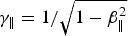 ${\rm \gamma} _{\rm \Vert} = 1/\sqrt {1 - {\rm \beta} _{\rm \Vert} ^2} $
,
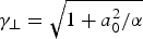 ${\rm \gamma} _ \bot = \sqrt {1 + a_0^2 /{\rm \alpha}}$
, β‖ = v
‖/c electron parallel velocity,
 $\tilde a = eE/m_{\rm e}c{\rm \omega} $
and α is polarization factor (α = 1 for circularly and α = 2 for linearly polarization). Furthermore, the total ponderomotive force on the electron sheath is the contribution of the ponderomotive force of the incident laser pulse
f
pi, and reflected pulse
f
pr.
 $${\bi F}_{\rm p} = {\bi f}_{{\rm pi}} + {\bi f}_{{\rm pr}} = \left( {1 - R^{\prime}{\left( {\displaystyle{{1 - {\rm \beta} _{\rm \Vert}} \over {1 + {\rm \beta} _{\rm \Vert}}}} \right)}^2} \right){\bi f}_{{\rm pi}},$$
in which R′ is the intensity reflection coefficient in the electron sheath reference frame. Additional factor ((1 − β‖)/(1 + β‖))2 in the second term comes from extraction (/compression) of the reflected pulse from relativistic electron layer (mirror). For example, for the Gaussian laser pulse, ponderomotive force is derived as,
 $${a_{\rm i} = a_0\; e^{ - 2\; ln2\; ({((x - x_0) - ct)}^2/l_{\rm p}^2 )}\; \to \nabla a^2 = \displaystyle{{ - 8\ln 2\;} \over {l_{\rm p}^2}} \left( {x - x_0 - ct} \right)\; a^2\; \hat x.} $$
The reflected pulse is extracted (/compressed) by the Doppler factor, (1 − β‖)/(1 + β‖), as follows,
 $$a_{\rm r} = \sqrt {{R}^{\prime}} a_0{\rm exp}\left( {\displaystyle{{ - 2ln2{( - x + x_0 - ct)}^2} \over {{((1 + {\rm \beta} _{\rm \Vert} /1 - {\rm \beta} )l_{\rm p})}^2}}} \right).$$
This rescaling factor occurs in the ponderomotive force of the compressed reflected laser pulse, which pushes electrons backwardly. An important effect of this factor is occurred when electron sheath moves backward (β‖ < 0). In this case strong backward ponderomotive force of the reflected pulse has an important effect on the electron sheath dynamics. Recent reports of the backward MeV acceleration of the electrons in the laser–foil interaction experiments (Orban et al., Reference Orban, Morrison, Chowdhury, Nees, Frische, Feister and Roquemore2015), can be described by this explanation.
The electrostatic force of the stationary ions in 1D analysis can be written by the capacitor model as,
 $${\bi F}_{\rm e} = - m_{{\rm e}0}{\rm \omega} _{\,p_{{\rm e0}}}^2 {\bi x}$$
Furthermore, electron sheath equation of motion is,
 $$\eqalign{\displaystyle{{dP_x} \over {dt}} & = F_{\rm p} + F_{\rm e} \cr & = \displaystyle{{4m_{{\rm e0}}c^2\ln 2\;} \over {{\rm \gamma} _ \bot l_{\rm p}^2}} {\rm \gamma} _{\rm \Vert} \left( {1 - {R}^{\prime}{\left( {\displaystyle{{1 - {\rm \beta} _{\rm \Vert}} \over {1 + {\rm \beta} _{\rm \Vert}}}} \right)}^2} \right) \cr & \quad \left( {x - x_0 - ct} \right)\ a^2 - m_{{\rm e}0}{\rm \omega} _{{\rm p}_{{\rm e0}}}^2 x.} $$
We obtain electron sheath dynamics by solving this equation numerically in the next section, but in this stage evolution of sheath thickness and density are reviewed. The electron density and plasma frequency of the sheath obtain from the compression of the background electrons into the sheath thickness (Fig. 1),
 $$n_{\rm e} = \displaystyle{{n_{{\rm e0}}\; (x + d)} \over d},\quad {\rm \omega} _{{\rm p}_{\rm e}}^2 = {\rm \omega}_{{\rm p}_{{\rm e0}}}^{2} \left( {\displaystyle{{x + d} \over d}} \right).$$
In the sheath rest frame, n e′ = n e/γ‖ and m e′ = γ⊥′ m e0, in which γ⊥′ = γ⊥, then plasma frequency is,
 $${\rm \omega}_{{\rm p}_{\rm e}}^{\prime 2} = \displaystyle{{{\rm \omega} _{{\rm p}_{{\rm e}0}}^2} \over {{\rm \gamma} _{\rm \Vert} {\rm \gamma} _ \bot{} ^{\prime}}} \left( {\displaystyle{{x + d} \over d}} \right) = \displaystyle{{{\rm \omega} _{{\rm p}_{{\rm e0}}}^2} \over {\rm \gamma}} \left( {\displaystyle{{x + d} \over d}} \right).$$
where, γ = γ‖γ⊥. In the electron sheath rest frame, laser skin depth can be written as,
 $$l_{\rm s}^{\prime} = \displaystyle{c \over {\sqrt {{\rm \omega} _{{\rm p}_{\rm e}}^{{{\prime}2}} - {\rm \omega} ^{\prime}2}}}. $$
We assume, l s′ = d′ = γ‖ d, then the Eq. (7) is self-consistent relation for determination of electron sheath thickness d. After some algebra electron sheath thickness obtains,
 $$d = \displaystyle{{ - x \pm \sqrt {\matrix{x^2 + 4[1 - {\rm \gamma} {\rm \omega} ^2/{\rm \omega} _{{\rm p}_{{\rm e0}}}^2 \hfill \cr \quad (1 - {\rm \beta} _{\rm \Vert} /1 + {\rm \beta} _{\rm \Vert} )]({\rm \gamma} c^2/{\rm \gamma} _{\rm \Vert} ^2 {\rm \omega} _{{\rm p}_{{\rm e0}}}^2 ) \hfill}}} \over {2[1 - {\rm \gamma} {\rm \omega} ^2/{\rm \omega} _{{\rm p}_{{\rm e0}}}^2 (1 - {\rm \beta} _{\rm \Vert} /1 + {\rm \beta} _{\rm \Vert} )]}}.$$
In the interaction of the ultra-short relativistic laser pulse (a
0 ≫ 1), longitudinal dynamics of the electron sheath may become relativistic. In this case, relativistic effects strongly disturb sheath dynamics, such as relativistic transparency. The relativistic transparency condition simply drives in the electron sheath rest reference frame by,
 ${{\rm \omega}} ^{\prime} \gt {\rm \omega}_{{\rm p}_{\rm e}}^{{\prime}2} $
, in which,
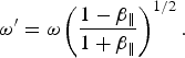 $${{\rm \omega}} ^{\prime} = {\rm \omega} \left( {\displaystyle{{1 - {\rm \beta} _{\rm \Vert}} \over {1 + {\rm \beta} _{\rm \Vert}}}} \right)^{1/2}.$$
After the straight algebra transparency condition obtains as,
 $$\displaystyle{{\rm \omega} \over {{\rm \omega} _{{\rm p}_{{\rm e0}}}}} \gt \sqrt {\displaystyle{{x + d} \over {d{\rm \gamma}}} \left( {\displaystyle{{1 + {\rm \beta} _{\rm \Vert}} \over {1 - {\rm \beta} _{\rm \Vert}}}} \right)}. $$
This condition may be fulfilled in the backward dynamics of the electron sheath, when laser frequency is up-shifted (and the electron sheath changes to the underdense plasmas).
Another important parameter in the electron sheath dynamics is its maximum forward displacement. Now we drive this maximum displacement by simple overestimate approximation and then in the next section, qualify our results by the numerical solution of the sheath dynamics [Eq. (4)]. Forward acceleration of the electron sheath begins with the interaction of the laser pulse's front side with the foil. In the rising part of the laser pulse, ponderomotive force is increased and then reaches zero in the center of the pulse. The maximum displacement of the sheath occurs approximately at the maximum ponderomotive force of the laser pulse, that is, when its gradient or the ponderomotive force's sign is changed. For the laser pulse with Gaussian profile,
 $a = a_0{\rm exp}( - 2\ln 2\; (x - x_0 - ct)^2/l_{\rm p}^2 )$
, this point occurs approximately at (x − x
0 − ct) ≈ l
p/2. We assume velocity of the electron sheath reverses at this point (β‖ = 0), then ponderomotive force at this point reduces to,
 $$F_{\rm p} = \displaystyle{{m_{{\rm e}0}c^2\ln 2\;} \over {{\rm \gamma} l_{\rm p}}}a_0^2 (1 - R).$$
By assuming equilibrium condition at this point, F p ≈ F e, maximum displacement is obtained,
 $$\eqalign{\displaystyle{{m_{\rm e}c^2\ln 2\;} \over {{\rm \gamma} _ \bot l_{\rm p}}}&a_0^2 (1 - {R}^{\prime}) = m_{\rm e}{\rm \omega} _{{\rm p}_{{\rm e0}}}^2 \ x_{{\rm max}} \to x_{{\rm max}} = \cr & \quad \displaystyle{{c^2\ln 2\; (1 - R^{\prime})} \over {l_{\rm p}{\rm \omega} _{{\rm p}_{{\rm e}0}}^2}} \displaystyle{{a_0^2} \over {\sqrt {1 + a_0^2 /{\rm \alpha}}}} \;} $$
This maximum displacement is a good scale for the foil critical thickness for the electron blow out regime. The electron blow out condition can be written for normalized parameters as,
 $$a_0 \gg \displaystyle{{{\tilde {\!l}}_{\rm p}{\tilde n}_{\rm e}\,\tilde {\!d}} \over {(1 - {R}^{\prime})\sqrt {\rm \alpha}}} $$
This criteria is a generalization of Kiefer condition,
 $a_0 \gg \tilde n_{\rm e}\,\tilde {\!d}$
[7], and our previous work,
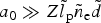 $a_0 \gg Z\,\tilde {\!l}_{\rm p}\tilde n_{\rm e}\,\tilde {\!d}$
[14]. The validity of this condition is qualified by the numerical results in the next section.
3. NUMERICAL RESULTS AND DISCUSSION
In this section electron sheath dynamic is derived by numerical solution of the Eq. (6). Laser pulse has a Gaussian profile with normalized amplitude a 0 and duration τ = l p /c. Pre-plasma slab constitutes from one species ion and electron with densities n i and n e = Zn i, where Z is ionization degree of ions. In the numerical procedure all quantities normalized by the following manner, but we assume laser wavelength is λ = 1 µm for exhibition of the real values of quantities.
 $$\eqalign{\tilde {\!t} & = {\rm \omega} t,\quad \tilde {\!v} = {\rm \beta} = \displaystyle{v \over c},\quad \tilde {\!x} = \displaystyle{{\rm \omega} \over c}x, \cr & \quad \tilde {\!E} = \displaystyle{{eE} \over {m_{\rm e}c{\rm \omega}}}, \quad \tilde {\!F} = \displaystyle{F \over {m_{\rm e}c{\rm \omega}}}, \quad {\tilde {\!\rm \omega}} _{{\rm pe}} = \displaystyle{{{\rm \omega}_{{\rm pe}}} \over {\rm \omega}}.} $$
Figure 2 shows electron sheath dynamics for the interaction parameters;
 $a_0 = 5,\; \;{\rm \tau} = 43\; \,{\rm f}s,\;{\rm and}\;{\rm \omega} _{{\rm p}_0}/{\rm \omega} = 10$
.
(a) Electron displacement and (b) its longitudinal momentum for interaction parameters;
 $a_0 = 5,\; \,{\rm \tau} = 43\,{\rm fs},\;{\rm and}\,{\rm \omega} _{{\rm p}_0}/{\rm \omega} = 10$
.

Maximum electron sheath displacement x max and maximum backward acceleration of electrons |P x |max are indicated in this figure. Electron sheath reaches to ~0.002 nm and then accelerated backward up to 43 eV. Figure 3 shows electron sheath dynamics for the ultra-relativistic laser pulse amplitude, a 0 = 50. In this case maximum displacement of the sheath increases to 0.13 nm and backward accelerated electron's energy reaches to 110 MeV. The MeV electron backward acceleration was reported in a recent experimental result (Orban et al., Reference Orban, Morrison, Chowdhury, Nees, Frische, Feister and Roquemore2015).
(a) Electron displacement and (b) its longitudinal momentum for ultra-relativistic case, a 0 = 50. Considerable electron backward acceleration (~110 MeV) is obtained.

In Figure 4, evolution of maximum electron sheath displacement is considered as a function of interaction parameters. The maximum displacement of the electron sheath is a good scale for the critical thickness of the foil for the electron blows out. There are some critical values for interaction parameters for occurrence of the electron blow out. Blow out for nanometer foil occurs in the interaction of intense (a 0 > 5) and ultra-short (τ < 10 fs) laser pulse with dilute target (ωp/ω < 20). Exact criteria for electron blow out referred in Eq. (15), a 0 ≫ τn e d.
Maximum electron sheath displacement is shown as a function of (a) laser normalized amplitude, (b) laser pulse duration, (c) normalized plasma frequency, and (d) reflection coefficient. In each shape other parameters set as,
 $a_0 = 20,\; \,{\rm \tau} = 27\,{\rm f}s,\quad \; R = 0.8\;{\rm \; and}\;{\rm \omega} _{{\rm p}_0}/{\rm \omega} = 10$
.

Increasing of the maximum electron sheath displacement x max(≈d) with increasing laser amplitude a 0 in the range, 5 < a 0 < 10, decreasing of d with increasing pulse duration τ or plasma density ωp/ω, are in agreement with Eq. (15). Dropping of displacement curves for a 0 > 20 is due to the relativistic transparency, which violates validity of the Eq. (15).
In Figure 5 displacement of the electrons in the finite thickness foil is considered and transition to the blow out regime clearly obvious. In contrast to the thick foil, increasing of the restoring electrostatic force is terminated when electron sheath goes over the foil thickness. Returning of the sheath at the end of the interaction is a legal result of our 1D analysis.
Electron displacement in different foil thicknesses for, a 0 = 5, τ = 43 fs, and ωp0/ω = 10. Electron blow out occurs for, <x max.

Figure 6, shows backward accelerated electron energy as a function of interaction parameters. There are threshold values for occurrence of the backward acceleration for any interaction parameters. For example, for our selected interaction parameters, backward acceleration does not occur for normalized laser amplitude less than, a 0t = 10 (~1019 w/cm2), or for laser pulse duration greater than τt = 25 fs.
Maximum electron backward acceleration is shown as a function of (a) laser normalized amplitude, (b) laser pulse duration, (c) normalized plasma frequency, and (d) reflection coefficient. In each shape other parameters are set as,
 $a_0 = 20,\; \;{\rm \tau} = 27\,{\rm fs},\;\; R = 0.8$
and
 ${\rm \omega} _{{\rm p}_0}/{\rm \omega} = 10$
.

At the end of this section results of 1D3V, PIC simulation code are presented for the interaction of laser pulse with normalized amplitude, a 0 = 45 and duration, τ = 9 fs with thin foil, d = 1.25 µm with normalized plasma frequency, ωp/ω = 2. Blown out electrons and backward accelerated electrons are indicated in Figure 7. Some part of electrons in the sheath blow out and another part of them accelerate backwardly.
PIC simulation results for interaction parameters a 0 = 45, τ = 9 fs, d = 1.25 µm, and ωp0/ω = 2. At t = 0, foil initiated at z = 0.

In Figure 8 dynamics of some test electrons initiated uniformly through the foil are shown. Blown out electrons, maximum electron displacement, and its backward acceleration are detectable in this figure. Electrons near the front surface of the foil initially push forward, and reach to a maximum displacement. In continuation these electrons accelerate backward up to about 60 MeV. Furthermore, electrons in the rear side of the foil leave the foil and accelerate up to 20 MeV forwardly.
Dynamics of some test electron from PIC simulation results for interaction parameters;
 $a_0 = 45,\; \;{\rm \tau} = 9\,{\rm fs},\;\; d = 1.25\,{\rm \mu}{\rm m},\;{\rm and}$
 ${\rm \omega} _{{\rm p}_0}/{\rm \omega} = 2$
.

4. CONCLUDING REMARKS
Electron dynamic in the interaction of intense laser pulse with solid targets has a substantial role in the subsequent phenomenon. Wide variety of applications associate to the laser–solid interaction such as, HHG, ion acceleration regimes, fast ignition in ICF, electron blow out and generation of RM. In this paper electron sheath dynamic is calculated by the simple 1D model. Ions are considered stationary, and ponderomotive force of the laser pulse and electrostatic restoring force of the background ions are two major forces exerted on the electron sheath layer. Some new events are introduced such as, violent backward ponderomotive force, the skin depth of the relativistic CEL and its transparency condition, electron blow out condition, and electron backward acceleration. Inclusion of these features in numerical procedure confirms some new behaviors such as electron blow out in the interaction of ultra-short laser pulse with thin foils, and electron backward acceleration of an intense laser pulse. Numerical results of 1D3V, PIC simulation code are in good agreement with these features.
ACKNOWLEDGEMENT
The authors are grateful to Mr. Meisam Taghipour for his good ideas.



