The increasing complexity of service environments for metallic materials – coupled with rising demands from aerospace, marine engineering, transportation, medical devices and civil infrastructure industries for surface-protecting materials that offer integrated functionality, long-term durability and environmental compatibility – has spurred extensive research interest in high-performance multifunctional coatings (Montemor, Reference Montemor2014; Li et al., Reference Li, Zhang, Liu, Li, Du and Dong2015; Xavier, Reference Xavier2023; Qian et al., Reference Qian, Liu, Cui, Wang, Wang and Bao2025). Conventional protective coatings, typically designed for a single function, suffer from inherent limitations in corrosion resistance, superhydrophobicity, self-cleaning/anti-smudge performance, anti-icing capability, anti-bacterial/anti-fouling activity, environmental adaptability, damage responsiveness and multifunctional synergy. These shortcomings render them increasingly inadequate for long-term service under complex operating conditions (Lv et al., Reference Lv, Song, Jiang and Wang2014; Wei et al., Reference Wei, Wang, Guo, Shen, Jiang and Zhang2015; Best & Gelling, Reference Best and Gelling2023; He et al., Reference He, Han, Yi, Xu, Hui, Wang and Zhou2025). Consequently, the development of multifunctional coatings capable of simultaneously integrating anti-corrosion/self-healing, superhydrophobicity, self-cleaning, anti-icing and anti-bacterial/anti-fouling properties – alongside the evolution of surface engineering strategies from single-function protection towards synergistic and adaptive protection – has emerged as a critical research frontier.
Functional protective coatings are typically designed using organic matrices integrated with functional fillers, and their performance enhancement largely depends on the structural characteristics, surface chemistry and interfacial interactions of the incorporated nanofillers (Cao et al., Reference Cao, Jones, Sikka, Wu and Gao2009; Farhadi et al., Reference Farhadi, Farzaneh and Kulinich2011; Chang et al., Reference Chang, Hsu, Weng, Hung, Chuang and Chang2013; Navarchian et al., Reference Navarchian, Joulazadeh and Karimi2014; Zhou et al., Reference Zhou, Pourhashem, Wang, Duan, Zhang and Hou2022; Zhang et al., Reference Zhang, Liu, Wang and Hou2025a; Wang et al., Reference Wang, Lian, Zhang, Zhao, Li, Tao and Liu2026). Among various candidate fillers (e.g. two-dimensional materials, metal oxides, silica and micro/nano-containers), attapulgite (ATP) – a naturally occurring one-dimensional fibrous hydrated magnesium aluminosilicate nanoclay – has demonstrated considerable promise for multifunctional coating applications owing to its unique crystal structure, abundant surface active sites and environmental compatibility (Belaroui et al., Reference Belaroui, Dali Youcef, Ouali, Bengueddach and Lopez Galind2014). ATP possesses a typical 2:1 layered-chain structure and rod-like crystal morphology (Wang & Wang, Reference Wang and Wang2016; Ding et al., Reference Ding, Huang, Wang, Wang and Wang2019), with continuous nanochannels distributed along the fibre axis (Zhang et al., Reference Zhang, Wang, Kang, Wang and Wang2018b), as well as a relatively high specific surface area (SSA), porosity and surface reactivity (Murray, Reference Murray2000; Suárez & García-Romero, Reference Suárez and García-Romero2011; García-Rivas et al., Reference García-Rivas, Sánchez del Río, García-Romero and Suárez2017; Galán, Reference Galán1996; Zhang et al., Reference Zhang, Wang, Tian, Wang and Wang2018c). These structural features endow ATP with multiple roles in coating systems (Liu et al., Reference Liu, Zhang, Hou, Pan, Zhao and Hou2018b; Feng et al., Reference Feng, Zhang, Mu, Wang, Chen and Zhang2022; Wu et al., Reference Wu, Wei, Shi and Zhao2023b; Li et al., Reference Li, Yin, Meng, Qiao, Zhang and Cai2025). First, when well dispersed and effectively integrated with the matrix, ATP increases the diffusion pathway for corrosive species penetrating the coating, thereby enhancing barrier performance. Moreover, the abundant silanol groups on the ATP surface provide a basis for grafting, surface wettability regulation and interfacial compatibility optimization (Liu et al., Reference Liu, Zhan and Zhang2024; Yang et al., Reference Yang, Li, Xu, Kang, Mu and Wang2024). Such modifications can impart superhydrophobicity, anti-icing and self-cleaning/anti-smudge functions to the coating. Second, its channel structure can serve as a micro/nano-container for active agents (e.g. corrosion inhibitors, anti-bacterial agents and low-surface-energy components), enabling the coating to achieve anti-bacterial/anti-fouling and self-healing functions. Owing to these characteristics, ATP can function not only as a reinforcing and barrier filler, but also as a micro/nano-container for storing active agents, offering the potential to integrate corrosion resistance, superhydrophobicity, self-cleaning/anti-smudge, anti-icing and anti-bacterial/anti-fouling properties (Dong et al., Reference Dong, Li, Zhang and Wang2018; Wang et al., Reference Wang, Wang, Jiang, Ji, Liu, Tian and Zhang2024).
Over the past decade, the research paradigm for ATP in coating systems has undergone a marked transition. Early studies primarily employed ATP as a filler to improve the mechanical properties and density of organic coatings (Lu et al., Reference Lu, Shen, Song, Shing, Tao and Nutt2005; Wang et al., Reference Wang, Li, Wang, Liu, Deng, Jiao and Yang2013b). Subsequently, with a deeper understanding of its channel structure and surface activity, ATP was increasingly used as a micro/nano-container for active agents, enabling controlled release and self-healing protection under external triggers (Ali et al., Reference Ali, Shi and Jan2026). Furthermore, its one-dimensional nanorod morphology has been exploited to construct anti-bacterial/anti-fouling surfaces with contact-killing effects or to serve as a loading micro/nano-container for anti-bacterial agents, thereby meeting the design requirements of green anti-bacterial systems with minimal chemical release (Jiang et al., Reference Jiang, Geng, Peng, Ni, Pei and Ye2024). More recently, by virtue of its one-dimensional architecture and assembly capability, ATP has been widely employed to construct micro/nano-hierarchical rough structures, imparting coatings with surface functionalities such as active corrosion protection, superhydrophobicity, self-cleaning/anti-smudge, anti-icing and anti-bacterial/anti-fouling performance (Xie et al., Reference Xie, Wei, Duan, Zhu, Yang and Chen2022). This evolution indicates that ATP has progressively transitioned from a conventional inert filler to a multifunctional filler capable of participating in interfacial regulation, active species loading and structural construction in advanced coating systems.
Despite its attractive application potential, natural ATP is commonly associated with impurities such as metal oxides, carbonates and other silicate minerals. It also suffers from particle agglomeration, partial channel blockage and insufficient utilization of surface active sites (Wang & Wang, Reference Wang and Wang2016; Suárez et al., Reference Suárez, García-Rivas, Morales, Lorenzo, García-Vicente and García-Romero2021). These factors directly affect its dispersibility, loading capacity and interfacial compatibility, ultimately compromising its functional performance in coating systems. Therefore, while preserving its rod-like morphology and crystal framework, the rational regulation of its microstructure, channel characteristics and surface chemistry through appropriate pretreatment strategies is crucial for achieving high-performance ATP-based applications (Wang et al., Reference Wang, Liang, Wang, Shi, Xu and Li2025d). To date, a variety of pretreatment approaches have been developed for ATP (Frini-Srasra & Srasr, Reference Frini-Srasra and Srasra2008; Tang et al., Reference Tang, Yang, Wang, Liang, Zhang and Liang2014; Wang et al., Reference Wang, Wang, Kang and Wang2015a; Li et al., Reference Li, Jiang, Liu, Shi, Zhang and Sun2017; Ding et al., Reference Ding, Zhang, Wang, Zhu, Wang and Wang2021; Zhang et al., Reference Zhang, Wang, Wang, Xu, Lu and Wang2022). Thermal treatment promotes the removal of adsorbed water and part of the structural water, improves channel accessibility and optimizes the SSA (Frini-Srasra & Srasr, Reference Frini-Srasra and Srasra2008). Acid treatment facilitates impurity removal, channel reopening and surface structure optimization and is frequently used to improve loading capacities (Ding et al., Reference Ding, Zhang, Wang, Zhu, Wang and Wang2021; Zhang et al., Reference Zhang, Wang, Wang, Xu, Lu and Wang2022). Alkali treatment, in contrast, is advantageous for increasing surface activity and interfacial reactivity (Wang et al., Reference Wang, Wang, Kang and Wang2015a). Hydrothermal or solvothermal treatment can further regulate ATP’s crystal phase, morphology and surface structure (Li et al., Reference Li, Jiang, Liu, Shi, Zhang and Sun2017). These pretreatment and modification strategies determine not only the structural and interfacial characteristics of ATP itself, but also its mode of action and performance in multifunctional coating systems.
The preceding discussion indicates that ATP-based multifunctional coatings have made notable progress in anti-corrosion, superhydrophobicity, self-cleaning, anti-icing and anti-bacterial/anti-fouling applications (Tang et al., Reference Tang, Yang, Wang, Liang, Zhang and Liang2014; Jing et al., Reference Jing, Mu, Zhang, Wang, Zhong, Liu and Wang2020; Li et al., Reference Li, Liang, Zhang and Zhang2023; Qiu et al., Reference Qiu, Yang, Zhang, Zhang, Li and Chen2023; Wu et al., Reference Wu, Wei, Shi and Zhao2023b; Wang et al., Reference Wang, Wang, Jiang, Ji, Liu, Tian and Zhang2024; Zhang et al., Reference Zhang, Liu, Jiang and Zhang2024b). Nevertheless, several critical challenges remain unresolved. For instance, the loading capacity and release kinetics of ATP when used as a micro/nano-container still lack precise regulation; the long-term service stability of coatings under coupled environments involving salt spray, ultraviolet irradiation, freeze–thaw cycling and mechanical wear requires systematic evaluation; green, fluorine-free surface modification strategies and integrated approaches for constructing multiple functionalities remain to be further developed; and, importantly, the dynamic interfacial interaction mechanisms among ATP, functional molecules, coating matrices and metallic substrates have not yet been fully elucidated. These issues considerably constrain the rational design, performance optimization and large-scale application of ATP-based multifunctional coatings.
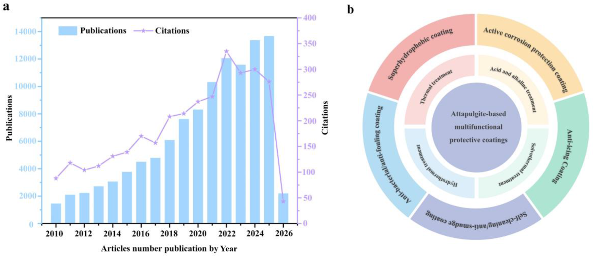
Extensive research has been reported on the development of nanoclay materials in fields such as environmental decontamination, advanced electrochemical energy conversion, corrosion protection, anti-bacterial applications and drug delivery (Yeh & Chang, Reference Yeh and Chang2008; Zaarei et al., Reference Zaarei, Sarabi, Sharif and Kassiriha2008; Zahidah et al., Reference Zahidah, Kakooei, Ismail and Raja2017; Wang et al., Reference Wang, Wang, Huang and Tang2020c; Leal et al., Reference Leal, Kuznetsova, Silva, Tedim, Wypych and Marino2022; Beryl & Xavier, Reference Beryl and Xavier2023; Wu et al., Reference Wu, Liao and Yang2023a; Xie et al., Reference Xie, Chen and Yang2023a; Biswas et al., Reference Biswas, Grathoff, Naidu and Warr2024; Mao et al., Reference Mao, Hong, Li, Gao, Jiang and Li2024a; Naciri et al., Reference Naciri, Ghazzal and Paineau2024; Xiang et al., Reference Xiang, Zheng, Lin, Wang, Zhang and Wang2024; Zhang et al., Reference Zhang, Qian, Xu, Said, Chen and Yang2025c). To the best of the authors’ knowledge, however, no review has been devoted to employing the same nanoclay for the construction of multifunctional coatings. Only a few reviews have summarized specific minerals for anti-corrosion coatings (Yeh & Chang, Reference Yeh and Chang2008; Zaarei et al., Reference Zaarei, Sarabi, Sharif and Kassiriha2008; Zahidah et al., Reference Zahidah, Kakooei, Ismail and Raja2017; Leal et al., Reference Leal, Kuznetsova, Silva, Tedim, Wypych and Marino2022; Beryl & Xavier, Reference Beryl and Xavier2023; Xiang et al., Reference Xiang, Zheng, Lin, Wang, Zhang and Wang2024). Therefore, a systematic review summarizing the development of ATP-based multifunctional coatings is urgently needed. As illustrated by the publication and citation trends in Fig. 1a, ATP-based multifunctional coatings have attracted increasing research attention from 2010 to 2026. This review provides a comprehensive and detailed discussion of the application of ATP-based nanoclays in multifunctional coatings (Fig. 1b), focusing on the pretreatment of ATP and its applications in anti-corrosion, superhydrophobicity, self-cleaning/anti-smudge, anti-icing and anti-bacterial/anti-fouling coatings. Specifically, the major pretreatment strategies – including thermal treatment, acid/alkali treatment, hydrothermal treatment and solvothermal treatment – are summarized, with an emphasis on their effects on the microstructure, channel characteristics and surface chemistry of ATP. Building on this foundation, the applications and working mechanisms of ATP in five key categories of functional coatings are further discussed: (1) its dual role in anti-corrosion coatings as both a physical barrier and a stimuli-responsive micro/nano-container for corrosion inhibitors; (2) its role in constructing surface micro/nano-roughness and low-surface-energy materials in superhydrophobic coatings; (3) its excellent superhydrophobic characteristics that endow coatings with self-cleaning/anti-smudge functions; (4) its application potential in anti-icing coatings for low ice adhesion, delayed icing and synergistic de-icing in combination with photothermal components; and (5) its functional contributions to anti-bacterial/anti-fouling coatings based on its one-dimensional nanostructure and active agent-loading capability. This review aims to establish relationships between ATP pretreatment strategies and coating structural design, interfacial regulation and ultimate functional performance, thereby providing valuable guidance for the development of multifunctional, environmentally friendly and application-orientated ATP-based coatings.
(a) Annual publication output and citation trends of ATP-based multifunctional protective coatings, reflecting growing research interest in this field (data sourced from the Web of Science Core Collection using the keywords ‘Attapulgite’ and ‘Coating’). (b) Schematic illustration of the review structure, outlining the pretreatment and modification strategies of ATP and their subsequent applications in various multifunctional protective coatings, including active corrosion protection, self-cleaning/anti-smudge, anti-bacterial/anti-fouling, anti-icing and superhydrophobic coatings.

Figure 1 Long description
Image A: Combined bar and line graph. Text at the top: Publications; Citations. Horizontal axis label: Articles number publication by Year. Range: 2010 to 2026. Left vertical axis label: Publications. Range: 0 to 14000. Right vertical axis label: Citations. Range: 0 to 400. Bars (Publications) by year: 2010: 1000 2011: 1500 2012: 2000 2013: 2500 2014: 3000 2015: 3500 2016: 4000 2017: 4500 2018: 5000 2019: 6000 2020: 7000 2021: 9000 2022: 11000 2023: 12000 2024: 11500 2025: 13000 2026: 13500 Line (Citations) by year: 2010: 100 2011: 110 2012: 120 2013: 130 2014: 150 2015: 170 2016: 190 2017: 210 2018: 230 2019: 250 2020: 270 2021: 300 2022: 320 2023: 350 2024: 330 2025: 300 2026: 50 Image B: Circular diagram with concentric rings. Center text: Attapulgite-based multifunctional protective coatings. Outer ring text segments: Active corrosion protection; Self-cleaning and anti-smudge; Anti-bacterial and anti-fouling; Anti-icing and superhydrophobic coatings. Inner ring text segments: Pretreatment and modification strategies; Thermal treatment; Acid and alkali treatment; Hydrothermal treatment; Solvothermal treatment.
Pretreatment of ATP
Due to their natural formation and paragenetic processes, ATP deposits typically contain coexisting mineral impurities, including metal oxides, carbonates and silicates. As a result, raw ATP often exhibits a broad particle-size distribution, severe agglomeration, partial pore blockage and a low density of surface active sites. These inherent limitations severely compromise its performance as a micro/nano-container, manifesting as low loading capacity, poor dispersibility, weak interfacial compatibility and insufficient structural stability. Consequently, to meet the stringent demands of applications such as nanomedicine delivery, catalysis and functional composite systems, ATP generally requires systematic pretreatment or activation to improve its SSA.
To date, thermal activation, acid/alkali treatment, hydrothermal treatment and solvothermal treatment have been widely adopted for the targeted modulation of ATP. The goal of these pretreatment strategies is to achieve an optimized ‘purification–structural regulation–surface functionalization’ cascade while preserving ATP’s characteristic rod-like morphology and crystalline framework. Specifically, pretreatment improves ATP in the following aspects. First, it improves SSA and pore volume. By removing mineral impurities and volatile components, the internal pore network is reopened, leading to increased SSA and pore volume, which in turn boosts ATP’s capacity for high loading capacity. And second, it improves dispersion and active site availability. Precise control over the degree of dehydroxylation, ion-exchange capacity and the density and charge characteristics of surface hydroxyl groups not only improves dispersion stability in solvents or polymer matrices but also strengthens interfacial interactions with active agents or functional components, thereby providing abundant reactive sites for subsequent grafting, adsorption or immobilization. In this section, we discuss how these strategies modulate ATP’s microstructure, pore architecture and surface chemistry, with the goal being to establish a robust material foundation for ATP in high-performance coating applications.
Thermal treatment
Thermal treatment is a straightforward and cost-effective modification strategy for ATP, enabling control of its structural features and surface properties by selectively removing physically adsorbed water, structurally bound water and volatile organic contaminants (Biswas et al., Reference Biswas, Sarkar and Naidu2016; Cai et al., Reference Cai, Yin, Zhang, Yang, Zhang and Wang2025). In practical applications, precise control of the thermal profile is critical for achieving the desired microstructure and surface chemistry, as excessive temperature and/or prolonged duration may trigger pore collapse, loss of the crystalline framework or undesirable phase transformations. Generally, water in ATP is classified into three states (Bradley, Reference Bradley1940): (1) surface/interparticle adsorbed water together with zeolitic water residing in the channel system; (2) coordinated water associated with Mg/Al coordination; and (3) structural hydroxyls/water located within the octahedral sheet (VanScoyoc et al., Reference VanScoyoc, Serna and Ahlrichs1979; Frini-Srasra & Srasr, Reference Frini-Srasra and Srasra2008). Although the characteristic dehydration temperatures may vary slightly among ATP sources due to differences in composition and morphology, the overall dehydration pathway remains qualitatively similar. The chemical composition of ATP varies significantly depending on its geological location, which in turn influences its thermal behaviour, structural stability and surface properties. Table 1 summarizes chemical composition data for representative ATPs from various geographical regions reported in the literature (Bradley, Reference Bradley1940; Belaroui et al., Reference Belaroui, Dali Youcef, Ouali, Bengueddach and Lopez Galind2014; Zhang et al., Reference Zhang, Wang, Zhang, Liu and Wang2015a; Ding et al., Reference Ding, Huang, Wang, Wang and Wang2019; Zhuang et al., Reference Zhuang, Li, Li and Yuan2022).
Chemical compositions (wt.%) of ATPs from various locations.

Table 1 Long description
Chemical oxide compositions in weight percent are listed for ATP samples from China (Anhui, Gansu, Jiangsu), Algeria, and USA (Georgia), covering SiO2, Al2O3, MgO, Fe2O3, CaO, Na2O, K2O, plus an Others column and references. SiO2 varies widely, from 40.32 in Algeria to 63.11 in China (Jiangsu), with China (Gansu) also high at 56.54 and USA (Georgia) at 55.03. Al2O3 ranges from 8.87 in Algeria to 14.52 in China (Gansu). MgO is highest in China (Jiangsu) at 13.61 and lowest in China (Gansu) at 5.34, while Fe2O3 peaks in China (Gansu) at 7.42 and is lowest in Algeria at 3.27. CaO is notably high in Algeria at 9.69 compared with 0.69 in China (Anhui) and 2.10 to 4.59 in the other Chinese samples; the USA (Georgia) CaO value is not reported. Na2O is very low where reported, from 0.009 in China (Anhui) to 0.24 in China (Jiangsu), and it is not reported for USA (Georgia). K2O ranges from 0.47 in USA (Georgia) to 3.72 in China (Gansu). Only China (Jiangsu) reports a nonblank Others value, 1.36, so comparisons for that column are limited.
n.d. = not determined.
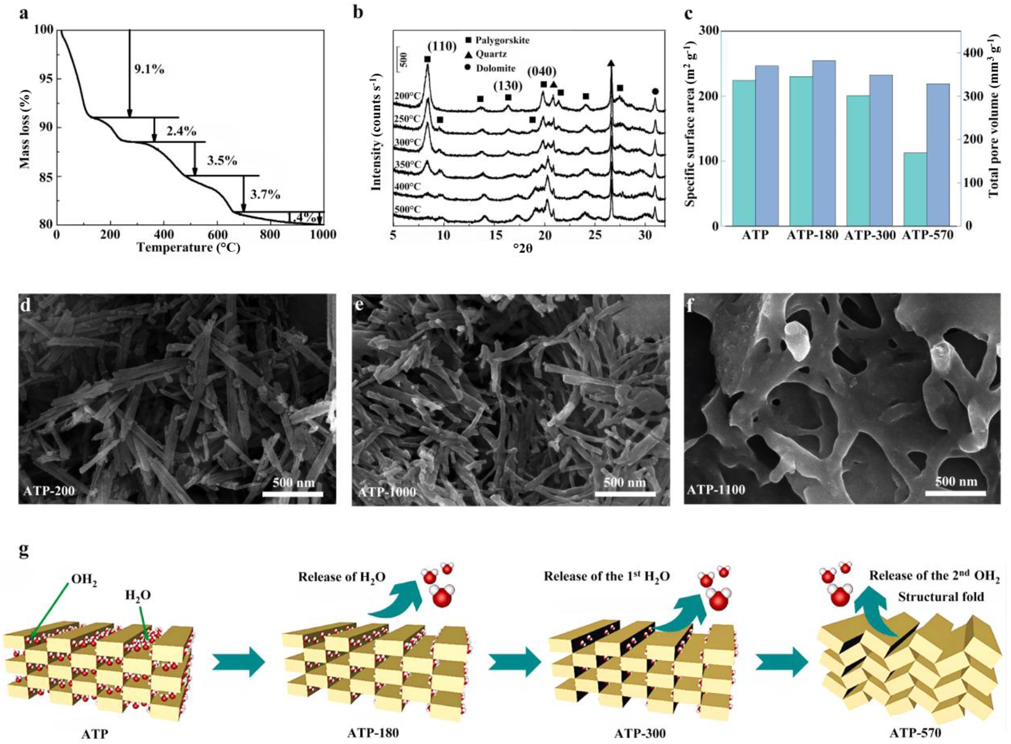
Thermal treatment significantly influences the morphology, phase composition and pore characteristics of ATP. Thermogravimetric analysis (TGA) profiles of ATP obtained across a range of temperatures are presented in Fig. 2a, elucidating the progressive structural evolution during thermal treatment as evidenced by distinct stages of mass loss and corresponding variations in thermal stability. Specifically, below 120°C, the removal of adsorbed water predominates and proceeds without discernible alteration of the crystal structure. In the range of 120–150 °C, desorption of a small amount of zeolitic water occurs, accompanied by a slight modification of the crystal structure (Kuang et al., Reference Kuang, Glenn and Detellier2004). In the 150–280°C range, most channel-hosted zeolitic water is removed; the unit-cell volume contracts while the framework is largely preserved, channel accessibility increases and the SSA correspondingly increases (Post & Heaney, Reference Post and Heaney2008; Cheng et al., Reference Cheng, Yang and Frost2011; Boudriche et al., Reference Boudriche, Calvet, Hamdi and Balard2012). At 340–480°C, coordinated water begins to be eliminated, potentially inducing structural folding; as the temperature approaches ∼450°C, this folding tends to become irreversible, causing damage to the periodic structure, collapse of the channel network and a rapid decrease in SSA (Kuang et al., Reference Kuang, Glenn and Detellier2004; Liu et al., Reference Liu, Chen, Chang, Cheng, Kong and Chen2013). At higher temperatures (500–700°C), dehydroxylation and decomposition of impurities become predominant, and the ATP progressively becomes amorphous. Above 800°C, pronounced phase transformations may occur, such as the formation of cristobalite. The phase composition as a function of thermal treatment temperature is shown in Fig. 2b. With increasing temperature, the intensities of the diffraction peaks at 8.3°2θ, 19.8°2θ, 21.4°2θ and 27.5°2θ gradually decrease. In addition, new diffraction peaks at 9.6°2θ and 18.8°2θ emerge, corresponding to the structural rearrangement of the (110) and (040) planes. At higher temperatures, the interplanar spacing of the (130) plane decreases due to the loss of coordinated water within the pore structure of ATP.
(a) Representative TGA profile of ATP. (b) X-ray diffraction trace of ATP subjected to thermal pretreatment at various temperatures (Liu et al., Reference Liu, Chen, Chang, Cheng, Kong and Chen2013). (c) SSA and pore volume of ATP as a function of temperature (Zhuang et al., Reference Zhuang, Li, Li and Yuan2022). (d–f) Scanning electron microscopy images of ATP at various temperatures: (d) 200°C, (e) 1000°C and (f) 1100°C (Wang et al., Reference Wang, Wang, Zhang, Zhang and Liang2020b). (g) Schematic illustration of the structural evolution of water molecules and channels in ATP (Zhuang et al., Reference Zhuang, Li, Li and Yuan2022).

Figure 2 Long description
The composite image consists of several panels related to ATP analysis at different temperatures. Panel (a) displays a thermogravimetric analysis (TGA) profile of ATP, showing mass loss percentages at specific temperature ranges: 9.1 percent at 120°C, 2.4 percent at 280°C and 3.5 percent at 580°C. Panel (b) presents X-ray diffraction traces of ATP subjected to thermal pretreatment at various temperatures, with peaks labeled for different phases such as palygorskite, quartz and diatomite. Panel (c) illustrates the specific surface area (SSA) and pore volume of ATP as a function of temperature, comparing ATP, ATP-180, ATP-360, ATP-580. Panels (d), (e) and (f) show scanning electron microscopy (SEM) images of ATP at temperatures 200°C, 1000°C and 1100°C, respectively, highlighting changes in morphology. Panel (g) provides a schematic illustration of the structural evolution of water molecules and channels in ATP, depicting the release of H subscript 2 O and OH subscript 2 at different stages: ATP, ATP-180, ATP-360 and ATP-580, leading to structural fold.
These structural changes significantly affect the surface properties of ATP. As shown in Fig. 2c, the SSA and pore volume are governed by the evolution of the crystalline framework and the removal of internal water/volatile matter. With increasing temperature, the SSA initially increases and then decreases. The enhancement observed for ATP-180 is ascribed to the loss of zeolitic water (Zhuang et al., Reference Zhuang, Li, Li and Yuan2022). Upon removal of coordinated water, ATP-300 begins to undergo structural rearrangement. In contrast, ATP-570 exhibits a pronounced decrease in SSA and pore volume due to the loss of structural and coordinated water, accompanied by concomitant channel collapse. These samples originate from Jiangsu, China, with their chemical compositions detailed in Table 1, and the suffix numbers denote their respective thermal treatment temperatures (180°C, 300°C and 570°C).
The dehydration of ATP with increasing temperature is accompanied by pronounced morphological changes, as shown in Fig. 2d–f. At 200°C (Fig. 2d), ATP retains its typical fibrous morphology, composed of well-defined rod-like nanostructures with relatively smooth surfaces and clear boundaries. At 1000°C (Fig. 2e), the fibrous structure is still largely preserved, although slight aggregation and local structural distortion can be observed. At ∼1100°C, significant melting of the ATP fibres is observed (Fig. 2f), leading to their fusion into a dense, interwoven network structure (Wang et al., Reference Wang, Wang, Zhang, Zhang and Liang2020b). The structural evolution of ATP during thermal treatment is schematically illustrated in Fig. 2g (Zhuang et al., Reference Zhuang, Li, Li and Yuan2022). Water species (adsorbed, zeolitic and coordinated) distributed within the one-dimensional channels govern structural stability. Their sequential removal upon heating induces progressive framework rearrangement and contraction, ultimately resulting in channel collapse.
These discussion demonstrates that thermal treatment is an effective strategy to enhance SSA, optimize microstructure and regulate the phase composition of ATP through the removal of physically and chemically bound water, the opening of pore channels and the activation of surface hydroxyl groups. These changes significantly improve the reactivity and functional performance of ATP. Nevertheless, thermal treatment has inherent limitations. Excessive heating may induce structural collapse, loss of crystallinity and undesirable phase transformations, thereby deteriorating the properties of ATP. A key challenge lies in precisely controlling the treatment parameters (e.g. temperature, duration and atmosphere) to achieve an optimal balance between structural activation and preservation. Future research should focus on several aspects. First, integrating thermal treatment with other modification strategies, such as molten salt-assisted methods, may reduce the required temperature while preserving the structural integrity of ATP. Second, the development of advanced in situ characterization techniques is essential for real-time monitoring of structural evolution during thermal treatment, which would enable a deeper understanding of the transformation mechanisms. Establishing a clear correlation between thermal treatment conditions and the evolution of ATP properties is crucial for customizing ATP-based functional materials. Ultimately, precise control of processing parameters enables the rational design of ATP with tailored properties for high-performance applications while promoting the development of energy-efficient and scalable modification processes.
Acid and alkaline treatment
Acid and alkaline treatment effectively remove impurities (e.g. carbonates, sulfates and metal oxides) from ATP, open its intrinsic channel structures and significantly increase both its SSA and pore volume (Zhang et al., Reference Zhang, Wang, Chen and Wang2010; Boudriche et al., Reference Boudriche, Calvet, Hamdi and Balard2011; España et al., Reference España, Sarkar, Biswas, Rusmin and Naidu2019). This treatment typically involves dispersing ATP in aqueous solutions of inorganic acids (e.g. HCl, H2SO4, HNO3 or H3PO4) to obtain the desired product by adjusting critical parameters, including acid concentration, reaction duration and temperature (Barrios et al., Reference Barrios, González, Rodríguez and Pozas1995; Ye et al., Reference Ye, Chen, Sheng, Sheng and Fu2006; Cai et al., Reference Cai, Xue and Polya2007; Shawabkeh et al., Reference Shawabkeh, Al-Khashman, Al-Omari and Shawabkeh2007; Volzone, Reference Volzone2007; Zhang et al., Reference Zhang, Wang, Chen and Wang2010). The acid treatment mechanism involves the progressive dissolution of the octahedral sheets of ATP, which removes interlayer metal cations. Residual octahedral fragments continue to support the tetrahedral sheets, thereby preserving the fundamental fibrous chain-layer framework (Gonzalez et al., Reference Gonzalez, Pesquera, Benito, Mendioroz and Pajares1989; Frini & Srasra, Reference Frini and Srasra2010). This structural evolution alters the surface properties of ATP: the leaching of metal cations cleaves some Si–O–M bonds, generating deprotonated Si–O– sites, which are subsequently protonated to form silanol groups under sustained acidic conditions. This process can significantly modify the surface properties of ATP and increase its SSA and porosity, increasing its potential as a micro/nano-container for active agents in the fields of corrosion protection and drug delivery (Ding et al., Reference Ding, Huang, Wang, Wang and Wang2019).
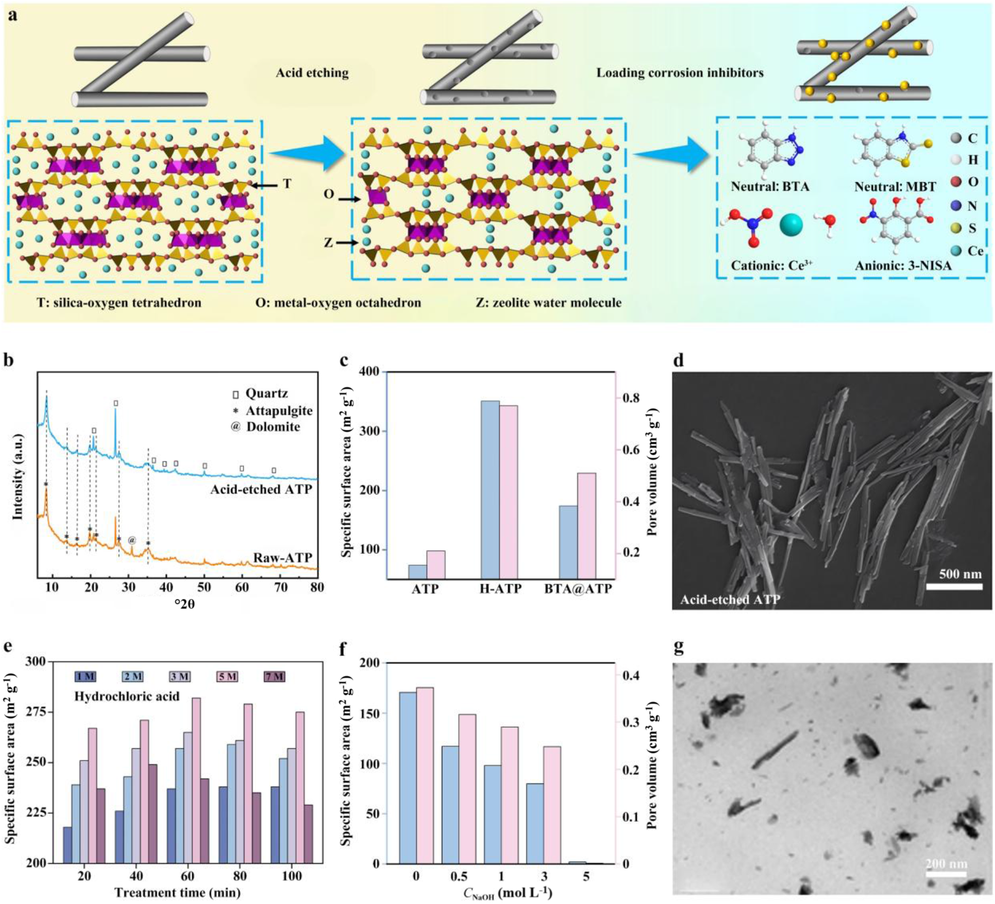
Numerous previous studies have reported the use of acid treatment strategies to improve crystal bundle disintegration, compositional optimization and pore architecture (Myriam et al., Reference Myriam, Suarez and Martin-Pozas1998; Guan et al., Reference Guan, Wang, Wang, Sun, Wang and Hu2018). The present work mainly focuses on optimizing acid concentration and type to establish preparation parameters that correlate with ATP structure. For example, HCl treatment has been widely used to tailor the structure and properties of ATP. As shown in Fig. 3a, acid treatment can transform ATP into micro/nano-containers suitable for storing active agents (Li et al., Reference Li, Yin, Meng, Qiao, Zhang and Cai2025). As illustrated in Fig. 3b, HCl treatment effectively removes interlayer metal cations and carbonate impurities from the octahedral sheets, leading to compositional purification and structural modification. By optimizing the HCl concentration, the SSA and pore volume increase from 74 m2 g⁻1 and 0.21 cm3 g⁻1 for pristine ATP to 351 m2 g⁻1 and 0.77 cm3 g⁻1 for acid-etched ATP, enabling a high active agent-loading capacity (Fig. 3c). Moreover, electrostatic repulsion between rod-like crystals is increased, promoting bundle dissociation and improving dispersibility (Fig. 3d). Further research has systematically investigated the effects of acid concentration and reaction duration on the SSA of ATP (Yeh et al., Reference Yeh, Wang, Tsai, Lin, Huang and Chen2013). The results revealed that excessive acidity or prolonged treatment induces physical degradation of ATP (e.g. thinning and shortening), loss of characteristic channel structures and even transformation towards amorphous silica, ultimately diminishing SSA (Fig. 3e). Acid type is another important parameter in determining the characteristics of ATP. One study compared the effects of HCl and H3PO4 treatments on ATP porosity, finding that HCl treatment preferentially expands meso/macro-pores, whereas H3PO4 treatment prompts micropore formation. Therefore, acid concentration and type play a crucial role in controlling the SSA and morphology of ATP. An optimal balance must be achieved between the moderate extraction of Mg, Al and other cations from octahedral sheets to unblock channels and improve micro/nano-container functionality and the prevention of excessive etching that compromises structural integrity. This strategic equilibrium ensures the preservation of the fibrous framework while maximizing ATP’s efficacy as a functional micro/nano-container.
(a) Schematic illustration of the preparation of inhibitor@ATP containers. (b) X-ray diffraction traces of pristine ATP and acid-etched ATP. (c) SSA and pore volume of pristine ATP, acid-etched ATP and benzotriazole (BTA)@ATP. (d) Scanning electron microscopy image of acid-etched ATP (Li et al., Reference Li, Yin, Meng, Qiao, Zhang and Cai2025). (e) Time-dependent evolution of SSA for ATP etched with various HCl concentrations (Yeh et al., Reference Yeh, Wang, Tsai, Lin, Huang and Chen2013). (f) Effect of NaOH concentration on the SSA and pore volume of ATP. (g) Transmission electron microscope image of ATP after pretreatment with 5 M NaOH (Wang et al., Reference Wang, Wang, Kang and Wang2015a). 3-NISA = 3-nitrosalicylic acid; MBT = 2-mercaptobenzothiazole.

Figure 3 Long description
Multi-panel scientific figure illustrating ATP pretreatment and characterization. The top row features a schematic of inhibitor@ATP preparation, showing acid etching and inhibitor loading with labeled components: T (silica-oxygen tetrahedron), O (metal-oxygen octahedron) and Z (zeolite water molecule). Neutral, cationic and anionic inhibitors are represented by colored spheres. The middle row includes X-ray diffraction traces comparing pristine and acid-etched ATP, highlighting mineral peaks. A bar graph shows specific surface area (SSA) and pore volume for ATP, BTA@ATP and BTA@NaATP, with acid-etched ATP having the highest SSA. A scanning electron microscopy image displays the fibrous structure of acid-etched ATP. The bottom row presents a bar graph of SSA over time for ATP etched with various HCl concentrations, indicating increased SSA with treatment time. Another graph shows the effect of NaOH concentration on SSA and pore volume, with higher concentrations reducing SSA. A transmission electron microscope image reveals ATP′s structure after 5 M NaOH pretreatment, showing dispersed particles. The layout follows a top-to-bottom, left-to-right reading order, enhancing understanding of how pretreatments alter ATP′s structural and surface properties.
Alkaline treatment of ATP exhibits distinct selectivity: under strongly alkaline conditions, cations such as Al3+ and Mg2+ within the octahedral sheets are progressively leached, concurrently inducing localized degradation and rearrangement of the Si–O tetrahedral framework. This selectivity is typically evidenced by a higher dissolution extent of Si4+ relative to Al3+ and Mg2+, with Al3+ leaching more readily than Mg2+ – a behaviour closely correlated with the spatial distribution of bond dissociation energies (Wang et al., Reference Wang, Wang, Kang and Wang2015a; Lu & Wang, Reference Lu and Wang2022). Alkaline treatment uniquely facilitates surface charge modulation and controlled structural evolution, substantially increasing the density of surface hydroxylation and thereby enhancing interfacial reactivity and functionalization potential for subsequent modifications (e.g. silanization and grafting; Wang et al., Reference Wang, Zhang and Wang2013a; He & Jin, Reference He and Jin2023; Lisuzzo et al., Reference Lisuzzo, Bertini, Lazzara, Ferlito, Ferrante and Duca2023). Previous studies have shown that the SSA of ATP decreases progressively with increasing NaOH concentration (Fig. 3f; Wang et al., Reference Wang, Wang, Kang and Wang2015a). Further structural analysis reveals that alkaline treatment exerts a concentration-dependent regulation on the structural evolution of ATP. The process proceeds via a controllable selective dissolution mechanism. Hydroxide ions preferentially attack the Si–O–Si and Si–O–M (M = Mg, Al) bonds, leading to framework cleavage and the formation of Si–O⁻. At relatively low to moderate NaOH concentrations (≤3.0 mol L⁻1), selective leaching of octahedral cations (e.g. Al3+ and Mg2+) occurs, resulting in only slight structural modification, while the fibrous morphology and the tetrahedral–octahedral framework remain largely preserved. In contrast, when the NaOH concentration increases to 5.0 mol L⁻1, extensive dissolution of Al, Mg and Si species from the crystal backbone occurs, leading to the destruction of the ribbon-layer structure and the eventual collapse of the pore system, as evidenced by morphological changes (Fig. 3g).
Acid and alkaline treatments provide effective routes for tuning the structure and surface properties of ATP. Acid treatment generally increases SSA, pore volume and dispersibility by removing impurities, leaching octahedral cations and reopening blocked channels. In contrast, alkaline treatment can induce structural evolution and surface hydroxylation through the selective dissolution of framework components. These changes are beneficial for improving the reactivity, storage capacity and subsequent functionalization of ATP.
Nevertheless, both treatments require careful control of the synthesis parameters to obtain the desired products. Excessive acid treatment may result in serious damage to the octahedral sheets and even promote the formation of amorphous silica, while strong alkaline treatment may cause framework collapse and destruction of the pore structure due to extensive dissolution of both octahedral cations and tetrahedral silica. A major challenge, therefore, lies in achieving sufficient structural activation without compromising the intrinsic framework stability of ATP. Future work should focus on improving the controllability of these chemical treatment processes and elucidating their underlying mechanisms. Combining acid or alkaline treatment with other approaches, such as thermal activation or template-assisted methods, may offer more precise regulation of pore architecture and surface chemistry. Moreover, research efforts should be directed towards tracking structural evolution during dissolution and reconstruction, so that the relationship between treatment conditions and the resulting structural and functional properties can be established on a more quantitative basis. Such efforts will be essential for the rational design of ATP with optimized performance and for the development of efficient and scalable treatment processes.
Hydrothermal treatment
Hydrothermal treatment involves subjecting a material to controlled temperature and pressure within a sealed system, using water as the reaction medium to induce dissolution, recrystallization, phase transformation and morphological reconstruction. This process enables precise tuning of ATP’s crystalline phase composition, pore-structure distribution and surface functional group states.
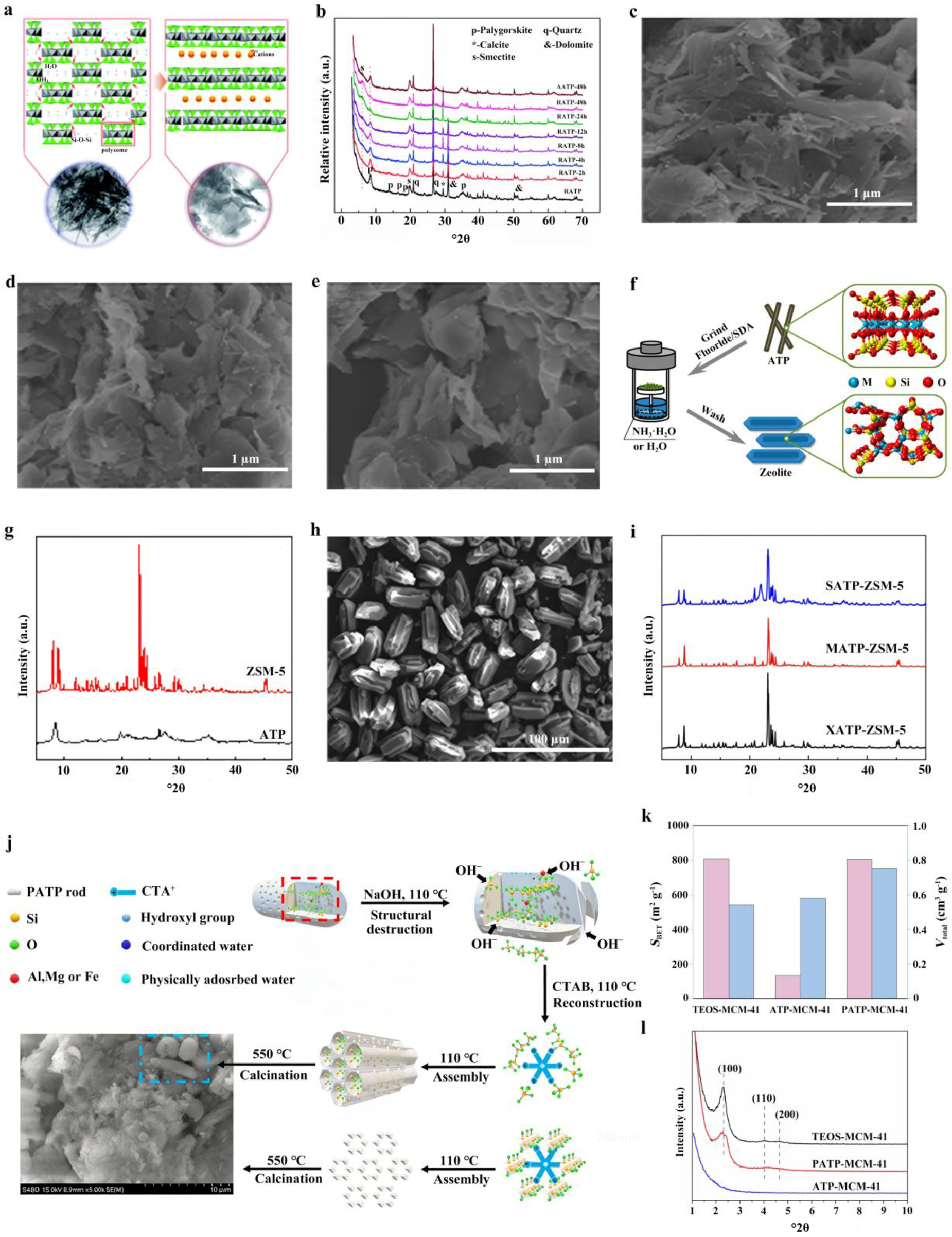
Under hydrothermal conditions, ATP can be transformed into a smectite phase. Dispersed ATP in weakly alkaline deionized water was almost completely transformed into smectite nanosheets through hydrothermal treatment (Wang et al., Reference Wang, Zhang, Tian and Wang2015b). As shown in Fig. 4a, the characteristic ATP diffraction peaks at 8.36°2θ and 13.89°2θ gradually disappeared, while a new smectite (001) peak emerged at 6.05°2θ (Fig. 4b), confirming the transformation of ATP into smectite. Correspondingly, with extending reaction time, ATP nanorods progressively shortened and transformed into nanosheets. At 2 h (Fig. 4c), only a limited number of sheet-like structures were observed, indicating that the transformation was still at an initial stage. By 12 h (Fig. 4d), the number of nanorods had significantly decreased, while nanosheets became the dominant morphology, suggesting that the transformation had advanced substantially. At reaction times of ≥24 h (Fig. 4e), the rod-like structures were almost entirely replaced by nanosheets, ultimately resulting in the formation of smectite nanosheets. Mechanistic studies revealed that this phase transformation does not proceed via the conventional ‘dissolution–recrystallization’ pathway; rather, it occurs through the reconnection of ‘polysome’ structural units following the ‘proximity principle’. Under alkaline conditions, the high-energy Si–O–Si bonds linking oppositely orientated Si–O tetrahedra are selectively cleaved, which promotes the alignment of tetrahedral layers. These layers then reorganize according to the ‘proximity principle’ under c/2 glide. In addition, Al3+ and Mg2+ participate in the reconstruction of the octahedral layers. Several studies (Yang et al., Reference Yang, Deng, Du and Jin2010; Jiang et al., Reference Jiang, Chen, Duanmu, Gu, Chen and Ni2014; Youcef et al., Reference Youcef, López-Galindo, Verdugo-Escamilla and Belaroui2020) have indicated that ATP can effectively replace expensive chemical precursors (e.g. tetraethyl orthosilicate (TEOS), colloidal silica and silicic acid) in the hydrothermal synthesis of high-value zeolites and ordered mesoporous materials. For instance, ZSM-5 zeolite (Zeolite Socony Mobil-5; Li et al., Reference Li, Jiang, Liu, Shi, Zhang and Sun2017) was synthesized using natural ATP as a silica source via a vapour-induced transformation (VIT) strategy (Fig. 4f). Water vapour permeates the ATP framework, inducing rearrangement and crystallization of Si/Al species to yield ZSM-5 with high crystallinity (yield ≈ 96%) and a well-developed porous architecture, exhibiting performance comparable to counterparts synthesized from pure chemical reagents. The X-ray diffraction (XRD) trace presents the typical peaks associated with an MFI-type (Mobil Five framework-type) structure, with characteristic diffraction peaks at 7–9°2θ and 22–25°2θ, while the ATP peak (typically at 8.4°2θ) disappears (Fig. 4g). The scanning electron microscopy (SEM) image of the resulting ZSM-5 (Fig. 4h) exhibits nearly perfect coffin-shaped crystals, which are fundamentally different from the fibrous morphology of ATP. The XRD traces of zeolites synthesized from various ATP sources (Fig. 4i) present the characteristic diffraction peaks of ZSM-5, demonstrating that ATPs from different regions with varying compositions can be used as Si/Al sources for zeolite synthesis via the VIT method.
(a) Proposed mechanisms for the transformation from RATP (ball-milled natural ATP) nanorods to smectite nanosheets. (b) XRD traces of RATP, RATP-2h, RATP-4h, RATP-8h, RATP-12h, RATP-24h, RATP-48h and AATP-48h. (c–e) Field-emission SEM images (Wang et al., Reference Wang, Zhang, Tian and Wang2015b) of (c) RATP-2h, (d) RATP-12h and (e) RATP-24h. (f) Scheme for the direct synthesis of zeolite from ATP via the VIT method. (g) XRD traces of ATP and ZSM-5. (h) SEM image of ZSM-5. (i) XRD traces of ZSM-5 from various ATP, XATP, MATP and SATP sources, denoting ATP from Xuyi, Mingguang and Shijiazhuang, China, respectively (Li et al., Reference Li, Jiang, Liu, Shi, Zhang and Sun2017). (j) Schematic of the structural transition of PATP–MCM-41 during MCM-41 construction. (k) SSAs and pore volumes of TEOS–MCM-41, ATP–MCM-41 and PATP–MCM-41. (l) Small-angle XRD traces of TEOS–MCM-41, ATP–MCM-41 and PATP–MCM-41 (Chen et al., Reference Chen, Zhang, Zhai, Chen, Miao and Li2025). CTAB = cetyltrimethylammonium bromide; SDA = structure-directing agent.

Figure 4 Long description
This infographic illustrates the transformation pathway of ATP-derived materials, highlighting structural and phase changes. The top row includes proposed mechanisms for RATP nanorods transforming into smectite nanosheets, XRD traces showing peak changes over time and SEM images depicting the transition from nanorods to nanosheets. The middle row presents the synthesis of zeolite from ATP using the VIT method, with XRD traces comparing ATP and ZSM-5 and an SEM image showing coffin-shaped ZSM-5 crystals. The bottom row features a schematic of PATP–MCM-41 structural transition, a bar chart comparing SSAs and pore volumes of different MCM-41 samples and small-angle XRD traces. Key trends include the disappearance of ATP peaks and emergence of smectite peaks, higher SSA in PATP–MCM-41 and distinct XRD patterns for different ATP sources. The layout follows a top-to-bottom reading order, providing a comprehensive view of material transformation and characterization.
SBA-15 (Santa Barbara Amorphous-15) and MCM-41 (Mobil Composition of Matter No. 41), two widely used mesoporous materials, can also be synthesized from ATP. For example, Jiang et al. (Reference Jiang, Chen, Duanmu, Gu, Chen and Ni2014) used ATP as both a template and a silica source. Acid-treated ATP was obtained through HCl-assisted hydrothermal treatment. The resulting product was then used as a hard template to construct a carbonaceous composite via vapour-phase polymerization of furfuryl alcohol. Subsequently, the template was removed, and the silica species were recovered through high-temperature hydrothermal alkaline treatment in NaOH solution. The recovered alkaline leachate was then mixed with an HCl solution containing Pluronic P123 (EO100–PO70–EO100, where EO = ethylene oxide, PO = propylene oxide and subscript numbers denote the average number of repeating units in each block), followed by hydrothermal assembly and calcination to produce SBA-15. This strategy highlights the dual role of ATP under hydrothermal conditions as both a template and a silicon source for the preparation of porous materials. In a related study, Chen et al. (Reference Chen, Zhang, Zhai, Chen, Miao and Li2025) further replaced TEOS with acidified ATP (PATP) to synthesize MCM-41, and they elucidated its formation mechanism (Fig. 4j). During acidification, H+ dissolves metal ions and attacks the silicate framework, generating abundant Si–O⁻ groups and thereby imparting a negative surface charge to PATP. During the hydrothermal process, OH⁻ promotes the fragmentation of PATP rods into colloidal particles and debris. These negatively charged species then electrostatically interact with cetyltrimethylammonium ions (CTA+), leading to the formation of PATP–CTA+ micellar rods. These subsequently self-assemble into a regular, mesoporous, ‘chrysalis-like’ structure (dominated by colloidal particles) and an irregular, mesoporous, ‘cotton-like’ structure (reconstructed from fragments). The resulting PATP–MCM-41 retains substantial Si–O⁻ groups. Finally, the template agent is removed by high-temperature calcination to yield the synthesized MCM-41. N2 adsorption–desorption analysis confirms that while its SSA is comparable to that of TEOS-derived MCM-41, it possesses a larger pore volume (Fig. 4k). Moreover, PATP–MCM-41 not only exhibits canonical MCM-41 features (Fig. 4l) but also preserves the residual macroporous structures inherited from pristine ATP.
Hydrothermal treatment is an effective approach for regulating the phase composition, morphology and pore structure of ATP under controlled aqueous conditions. Through phase transformation, structural reconstruction and template-directed assembly, ATP can be converted into a variety of value-added materials, including other nanoclay minerals, zeolites and ordered mesoporous structures. These transformations greatly expand the structural tunability of ATP-derived materials and increase their potential for further functional applications. However, the outcome of hydrothermal treatment is highly sensitive to processing conditions. Inappropriate reaction parameters may lead to incomplete conversion, excessive framework dissolution, structural heterogeneity and poor pore ordering, all of which are detrimental to material performance. The key challenge, therefore, lies in directing the transformation process in a controlled manner while preserving the desired structural features. Future studies should pay greater attention to the influence of precursor characteristics on hydrothermal behaviour, particularly for ATP raw materials from various geological locations. A deeper understanding of how phase, morphology and pore structure evolve under various hydrothermal conditions will be essential for elucidating the transformation pathways. Furthermore, more informative characterization of intermediate states during treatment would help to reveal the mechanisms governing dissolution, recrystallization and structural organization. Practical aspects of hydrothermal processing – including energy consumption, reagent recycling and scalability – should also be considered. Progress in these areas will support the development of more controllable and economically viable routes for preparing ATP-derived materials with tailored structures and properties.
Solvothermal treatment
Solvothermal treatment has been widely adopted for the controlled synthesis of novel inorganic nanomaterials (Mu et al., Reference Mu, Wang and Wang2013b; Wang et al., Reference Wang, Wang, Kang and Wang2013c; Xu et al., Reference Xu, Wang and Wang2013a; Zhang et al., Reference Zhang, Wang, Tian, Wang and Wang2018c; Tan et al., Reference Tan, Yin, Zheng, Di, Sun and Li2021). This approach utilizes solvents (e.g. organic solvents, alcohols), thereby offering a more versatile chemical environment for regulating the structure, morphology and physicochemical properties of the nanomaterials. During solvothermal treatment, the solvent medium not only facilitates the deagglomeration and dispersion of crystalline bundles but also tailors the surface chemistry and crystal microstructure. Notably, during the solvothermal treatment of natural ATP, organic solvent molecules may engage in specific interactions with the mineral, partially substituting structural water molecules. This induces a synergistic evolution of both structure and functionality, laying the foundation for its subsequent application as a functional filler in composite materials.
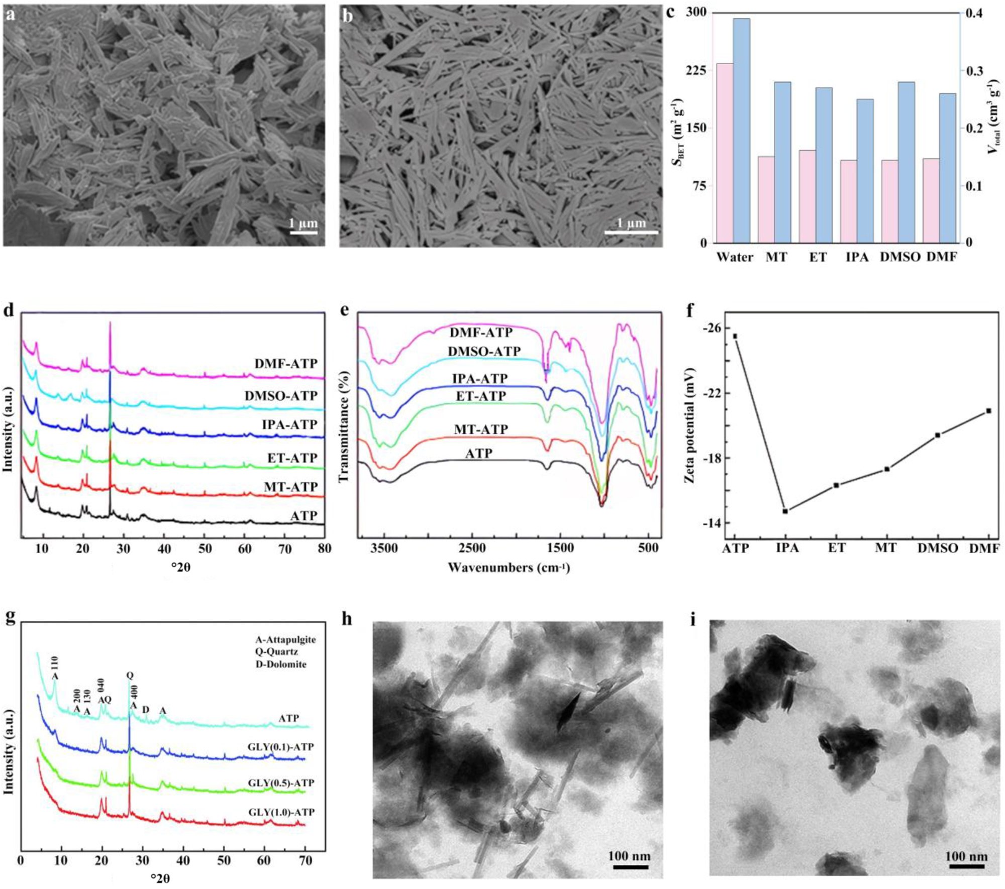
The morphology, surface characteristics and pore structure of ATP can be modulated by optimizing the solvent during the solvothermal treatment process. One study (Xu et al., Reference Xu, Wang and Wang2013b) systematically investigated the influence of various solvent media – namely water, methanol (MT), ethanol (ET), isopropanol (IPA), dimethylformamide (DMF) and dimethyl sulfoxide (DMSO) – in combination with high-pressure homogenization on the dispersibility of ATP. Compared to the large-sized bundles of pristine ATP (Fig. 5a), DMSO-treated ATP exhibited effectively promoted deagglomeration, yielding highly dispersed, individual rod-like crystals (Fig. 5b). The results demonstrated that solvent molecules can intercalate into the pore channels of ATP, leading to host–guest interactions, while simultaneously improving the SSA and pore volume (Fig. 5c). In contrast, the isopropanol-treated system imparted optimal colloidal stability to the suspension, achieving a viscosity as high as 2364 mPa·s. This study highlights the critical roles of solvent parameters (e.g. vapour pressure, viscosity and surface tension) in regulating the dispersion behaviour of ATP, providing a processing foundation for obtaining highly dispersed ATP without the need for the surfactants or high-temperature treatments typically required in conventional strategies.
(a) Field-emission SEM (FESEM) image of natural ATP. (b) FESEM image of homogenized ATP dispersed in DMSO. (c) SSA and total pore volume of homogenized ATP in various liquid media (Xu et al., Reference Xu, Wang and Wang2013b). (d) XRD traces, (e) Fourier-transform infrared spectroscopy and (f) zeta potential of pristine ATP and solvothermally treated ATP in various solvents (MT, ET, IPA, DMSO and DMF; Zhang et al., Reference Zhang, Wang and Wang2015c). (g) XRD traces of ATP, GLY(0.1)-ATP, GLY(0.5)-ATP and GLY(1.0)-ATP. (h) Transmission electron microscopy (TEM) image of GLY(0.5)-ATP. (i) TEM image of GLY(1.0)-ATP (Zhang et al., Reference Zhang, Wang, Kang, Zong and Wang2015b).

Figure 5 Long description
The composite contains nine panels examining how solvent treatment and glycerol modification affect the structural and surface properties of attapulgite samples. Panel (a) is a field-emission scanning electron microscopy image of natural attapulgite showing tightly bundled rod-like structures at a scale bar of 1 micrometer. Panel (b) is a field-emission scanning electron microscopy image of attapulgite homogenized in dimethyl sulfoxide at a scale bar of 1 micrometer, showing more separated individual rod-like crystals compared to panel (a). Panel (c) is a grouped bar chart comparing specific surface area and total pore volume of homogenized attapulgite across six solvent media. The x-axis lists the solvents: Water, methanol, ethanol, isopropanol, dimethyl sulfoxide and dimethylformamide. The left y-axis is labeled S subscript BET in m superscript 2 g superscript -1, ranging from 0 to approximately 300 in increments of 150. The right y-axis is labeled V subscript total in cm superscript 3 g superscript -1, ranging from 0 to approximately 0.4. Each solvent has two bars representing the two separate measures. Dimethylformamide and dimethyl sulfoxide show the tallest bars for specific surface area among the solvents shown. Panel (d) shows overlaid X-ray diffraction diffractograms for pristine attapulgite and five solvent-treated attapulgite samples: methanol-attapulgite, ethanol-attapulgite, isopropanol-attapulgite, dimethyl sulfoxide-attapulgite and dimethylformamide-attapulgite. The x-axis is labeled 2 theta in degrees, ranging from 10 to 70. The y-axis is labeled Intensity in arbitrary units. Multiple diffraction peaks are visible across the 10 to 35 degree region for all samples, with broadly similar peak positions across the six overlaid traces. Panel (e) shows overlaid Fourier-transform infrared spectroscopy transmittance spectra for the same six samples. The x-axis is labeled Wavenumbers in cm superscript -1, ranging from approximately 500 to 3500. The y-axis is labeled Transmittance. Each sample trace shows absorption bands in the 400 to 1200 cm superscript -1 region and near 3400 cm superscript -1, with the six curves closely overlapping. Panel (f) is a line graph showing zeta potential for attapulgite and the five solvent-treated samples. The x-axis lists: attapulgite, isopropanol, ethanol, methanol, dimethyl sulfoxide and dimethylformamide. The y-axis is labeled Zeta potential in millivolts, with values ranging from approximately minus 26 to minus 14. The plotted values increase from approximately minus 25 millivolts for attapulgite toward approximately minus 15 millivolts for dimethylformamide, showing a consistent upward trend across the series. Panel (g) shows overlaid X-ray diffraction diffractograms for four samples: attapulgite, GLY(0.1)-attapulgite, GLY(0.5)-attapulgite and GLY(1.0)-attapulgite. The x-axis is labeled 2 theta in degrees, ranging from 10 to 70. The y-axis is labeled Intensity in arbitrary units. A legend identifies peaks with labels A for attapulgite, Q for quartz and D for dolomite. Peaks are marked at approximately 8, 20 and 27 degrees across the four traces. Panel (h) is a transmission electron microscopy image of GLY(0.5)-attapulgite at a scale bar of 100 nanometers, showing elongated rod-like structures. Panel (i) is a transmission electron microscopy image of GLY(1.0)-attapulgite at a scale bar of 100 nanometers, showing darker, more aggregated particle regions compared to panel (h).
Further work investigated the effects of solvothermal treatment on the structure and surface properties of natural ATP using solvents of various polarities, including methanol, ET, IPA, DMF and DMSO (Zhang et al., Reference Zhang, Wang and Wang2015c). The results revealed that solvent molecules can enter the nanochannels formed by the tetrahedral–octahedral sheets of ATP, and this intercalation behaviour was found to depend primarily on solvent polarity (Barrer & Mackenzie, Reference Barrer and Mackenzie1954). Strongly polar solvents such as DMSO and DMF were capable of intercalating into the channel structure of ATP, leading to shifts in the (110) diffraction peak and changes in its intensity, indicative of a pronounced intercalation effect. In contrast, solvents with lower polarity – namely MT, ET and IPA – tended to adsorb on the surface and exerted minimal influence on the crystal structure (Fig. 5d). In terms of morphological evolution, ATP treated with MT and DMF predominantly existed as individual rod-like crystals, whereas those treated with ET and IPA still retained some small-sized crystal bundles. Furthermore, carbon species were detected on the surface of the treated ATP, with the DMF-treated group exhibiting the highest carbon density, further confirming that solvent molecules underwent certain chemical or physical interactions with the crystal surface. The presence of CH3-related vibrational bands in the infrared spectra also provided evidence for the residual attachment or grafting of solvent groups onto the ATP surface (Fig. 5e). Zeta-potential measurements (Fig. 5f) showed that pristine ATP had a potential of –25.5 mV, which increased to varying degrees after solvothermal treatment (e.g. –14.7 mV for IPA and –20.9 mV for DMF), reflecting changes in surface charge characteristics. These variations are closely associated with the modification of the electrical double layer and the adjustment of surface functional groups.
The solvothermal-modified, HCl-purified ATP in the presence of glycine (GLY) at 180°C, pH 12, at a solid-to-liquid ratio of 1:100, for 60 h can cleave the Si–O–Si and Si–O–M bonds, inducing crystal structure evolution (Zhang et al., Reference Zhang, Wang, Kang, Zong and Wang2015b). Increasing GLY concentration progressively decreased the diffraction intensities of the ATP (110), (200) and (130) planes, indicating pronounced amorphization accompanied by silicate tetrahedral chain rearrangement and a reduced dolomite phase (Fig. 5g). Glycine concurrently reacted under hydrothermal conditions, grafting carboxyl (–COOH), amino (–NH2) and carboxylate (–COO⁻) groups onto the surface, increasing surface negative charge density and metal complexation capacity. Pristine ATP exhibited dense, rod-like crystal bundles; after modification, bundles disaggregated, rods shortened and a rod–sheet composite structure formed (Fig. 5h). Excessively high GLY concentrations induced excessive amorphization (Fig. 5i). These structural and morphological changes increase the density of accessible active sites and pore utilization efficiency.
Solvothermal treatment is an effective approach for regulating the dispersion behaviour, surface chemistry, pore structure and microstructural evolution of ATP through a solvent-involved reaction environment. Through solvent-assisted deagglomeration, channel intercalation, surface interaction and structural reconstruction, ATP can be modified to exhibit improved dispersibility, altered surface charge characteristics and increased accessibility of active sites. These changes provide an important basis for the controllable preparation of ATP with tailored physicochemical properties.
However, solvothermal treatment also has inherent limitations. The modification outcome is highly sensitive to solvent type and processing parameters, and the respective effects of solvent polarity, viscosity, vapour pressure and hydrogen-bonding capability have not yet been fully elucidated. Under inappropriate conditions, solvothermal treatment may result in insufficient deagglomeration, unstable surface modification, retention of solvent-derived species or excessive structural disorder and amorphization, thereby impairing the structural integrity of ATP. Future work should emphasize both mechanistic understanding and process controllability. In particular, systematic comparison of various solvent systems, together with analysis of their physicochemical properties, is needed to establish quantitative relationships between solvent characteristics and the resulting changes in ATP structure and properties. More attention should also be paid to distinguishing the respective roles of surface adsorption, channel intercalation, chemical association and framework reconstruction during solvothermal treatment. Furthermore, the recycling of residual solvent-derived species and their influence on the stability and reactivity of modified ATP require further clarification. From a practical perspective, the development of recyclable, low-toxicity and scalable solvent systems will be essential for expanding the applicability of solvothermal modification. Progress in these areas will support the more rational and controllable design of ATP with tailored structures and surface properties while also promoting the development of efficient and scalable modification processes.
Application of ATP-based coating
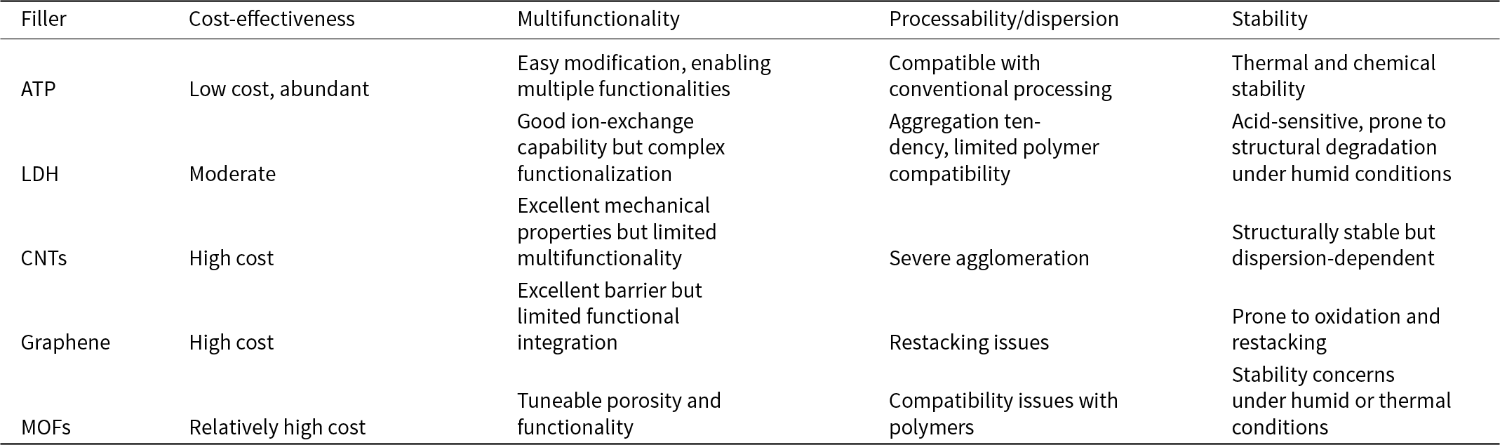
High-performance coatings rely significantly on high-quality functional fillers to improve their properties and performance. Despite the widespread use of various nanomaterials, current functional coatings still face challenges in active-agent immobilization, sustained performance, interfacial stability and multifunctional integration. Owing to its inherent channels, modifiable surface and good dispersibility, ATP can host active species (e.g. corrosion inhibitors, anti-bacterial agents and hydrophobic molecules) for controlled release and prolonged protection while also imparting functionalities such as self-cleaning, superhydrophobicity, anti-bacterial activity and anti-icing through surface and structural regulation. As shown in Table 2, compared to layered double hydroxides (LDHs), carbon nanotubes (CNTs), graphene and metal–organic frameworks (MOFs), ATP combines low cost, abundant availability, processing compatibility and structural stability, demonstrating strong potential for large-scale applications. Accordingly, this section focuses on modified ATP as a functional filler and micro/nano-container for developing functional coatings with self-healing, superhydrophobic, self-cleaning, anti-bacterial and anti-icing properties.
Comparative advantages of ATP over representative fillers in functional coating applications.

Table 2 Long description
Comparison of five fillers across cost-effectiveness, multifunctionality, processability or dispersion, and stability for functional coating use. ATP is described as low cost and abundant, easy to modify for multiple functions, compatible with conventional processing, and thermally and chemically stable. LDH is moderate in cost with good ion-exchange but complex functionalization, tends to aggregate with limited polymer compatibility, and is acid-sensitive with humidity-related structural degradation. CNTs and graphene are both high cost; CNTs offer excellent mechanical properties but limited multifunctionality and suffer severe agglomeration, while graphene offers an excellent barrier but limited functional integration and has restacking and oxidation issues. MOFs are relatively high cost with tunable porosity and functionality but show polymer compatibility challenges and stability concerns under humid or thermal conditions. Overall trend: ATP combines affordability, easier processing, and robust stability, whereas the other options trade higher cost for specific strengths but commonly face dispersion and environmental stability drawbacks.
Superhydrophobic coatings
Superhydrophobic surfaces have garnered extensive attention over the past two decades due to their unique water-repellent characteristics, which impart self-cleaning and anti-fouling properties. Defined by a water contact angle (CA) exceeding 150° and a sliding angle (SA) below 10° (Wei et al., Reference Wei, Zhang, Cao, Huo, Huang and Zhang2023), these surfaces arise from the synergistic effect of specific micro/nano-scale topographic features and a low-surface-energy chemical composition. One-dimensional rod-shaped ATP possesses unique structural characteristics and abundant active sites for chemical modification, facilitating surface functionalization with silane coupling agents, polymers or inorganic nanoparticles. More importantly, ATP can self-assemble or undergo specific aggregation to form hierarchical micro/nano-structures, providing an ideal physical skeleton for constructing superhydrophobic surfaces that exhibit the Cassie–Baxter state.
Silane coupling agents are widely used to modify ATP so as to impart superhydrophobicity. The modification process involves hydrolysis of the silane coupling agent to generate hydroxyl groups, which subsequently react with the hydroxyl groups on the ATP surface, resulting in covalently bonded, silane-modified ATP. Commonly used silane coupling agents include long-chain alkylsilanes or fluorosilanes, which contain alkyl or fluorine functional groups that confer water-repellent properties (Zhang et al., Reference Zhang, Tian, Zhang and Wang2018a, Reference Zhang, Liu, Zhan and Hou2024a; Dong et al., Reference Dong, Ding, Wei, Tian, Nan and Zhang2023; Meng et al., Reference Meng, Wang, Wang, Lyu, Chen, Lyu and Nie2024; Wang et al., Reference Wang, Wang, Wang and Zhang2025b). Numerous studies have employed fluorine-free silane coupling agents to modify ATP for superhydrophobic applications (Long et al., Reference Long, Yin, Mu, Wang, Hu and Li2020; Liu et al., Reference Liu, Zhan and Zhang2024; Wang et al., Reference Wang, Wang, Jiang, Ji, Liu, Tian and Zhang2024, Reference Wang, Wang and Zhang2025a; Zhang et al., Reference Zhang, Zhang, Xu and Hou2025b).
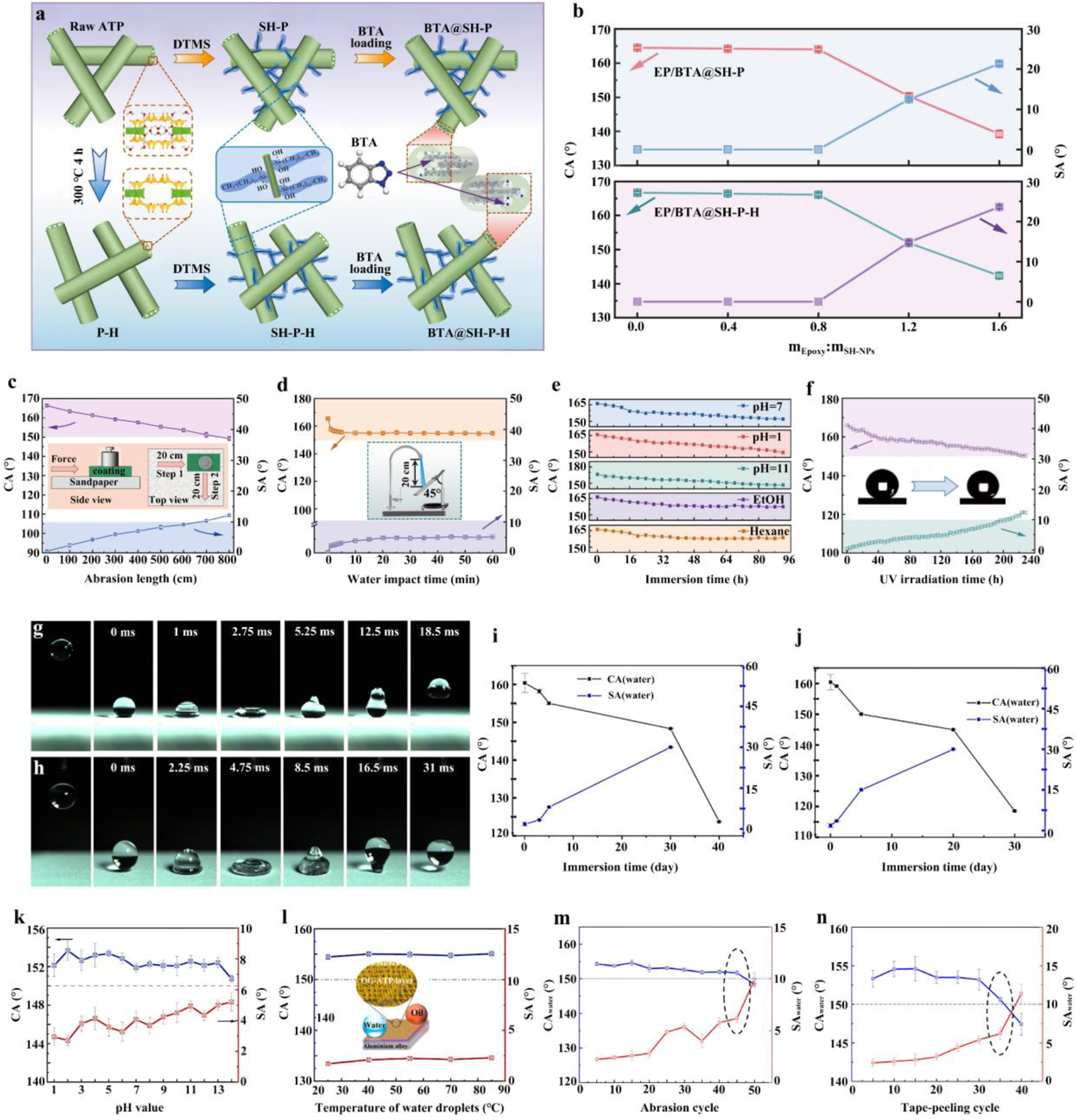
An ATP-based filler (BTA@SH-P-H, where BTA = benzotriazole and SH-P-H = natural ATP; Fig. 6a) was developed by modifying ATP with n-dodecyltrimethoxysilane (DTMS) and subsequently loading it with BTA (Wang et al., Reference Wang, Wang, Wang and Zhang2025b). The hydrophobicity of the resulting coating was systematically investigated by adjusting the mass ratio of epoxy (EP) to fillers (Fig. 6b). When the ratio was below 0.8, the water CA remained at nearly 165° and the SA was close to 0°, with only slight variations observed for EP/BTA@SH-P and EP/BTA@SH-P-H. Further increasing the EP content caused the coating to lose its superhydrophobic properties, as the excess hydrophilic EP dominated the wettability of the composite coating. The hydrophobicity of the EP/BTA@SH-P-H coating after mechanical damage is shown in Fig. 6c. As the abrasion distance increased, the CA decreased and the SA increased due to deterioration of the rough structure and loss of coating components. When the abrasion distance reached 800 cm, the coating transitioned from a superhydrophobic to a hydrophobic state. Additionally, after 10 min of high-velocity water impact (25 kPa), the CA and SA of the coating were 155.0° ± 0.89° and 4.0° ± 0.43°, respectively (Fig. 6d). Following chemical durability testing (92 h of immersion; Fig. 6e) and ultraviolet (UV) resistance testing (Fig. 6f), the coating maintained its superhydrophobic state, indicating good chemical stability and suitability for long-term practical applications.
(a) Schematic illustration of the preparation process for BTA-loaded superhydrophobic ATP containers. (b) Water CA and SA of composite coatings as a function of the EP resin to superhydrophobic nanoparticle mass ratio (thermally untreated SH-P and 300°C-activated SH-P-H; Wang et al., Reference Wang, Wang, Wang and Zhang2025b). (c,d) Evolution of CA and SA during (c) sandpaper abrasion and (d) water impact testing (Wang et al., Reference Wang, Wang, Wang and Zhang2025b). (e) CA of the EP/BTA@SH-P-H coating as a function of immersion time in various media: organic solvents (ethanol and n-hexane), acidic solution (pH 1), alkaline solution (pH 14) and saline solution (3.5 wt.% NaCl, pH 7; Wang et al., Reference Wang, Wang, Wang and Zhang2025b). (f) CA and SA of the coating as a function of UV irradiation time (Wang et al., Reference Wang, Wang, Wang and Zhang2025b). (g,h) Photographs of the SMP-BTA/fluoro-ATP-coated Mg alloy showing the impact and rebound behaviour of (g) a 3.5 wt.% NaCl droplet and (h) an n-hexadecane droplet (10 μL; Zhang et al., Reference Zhang, Wei, Li, Zhao and Zhang2021). (i,j) Variation in superhydrophobicity of the SMP-BTA/ATP coating during (i) immersion testing and (j) neutral salt spray testing (Zhang et al., Reference Zhang, Wei, Li, Zhao and Zhang2021). (k,l) CA and SA of the superamphiphobic OG-ATP/EP bilayer coating measured with droplets of (k) different pH values and (l) different temperatures (Zhang et al., Reference Zhang, Liu, Zhan and Hou2024a). (m,n) CA and SA of water and n-hexadecane on the superamphiphobic bilayer coating after (m) sandpaper abrasion and (n) tape-peeling cycles (Zhang et al., Reference Zhang, Liu, Zhan and Hou2024a).

Figure 6 Long description
The composite image includes multiple panels related to superhydrophobic and superamphiphobic coatings. The first panel illustrates the preparation process for BTA-loaded superhydrophobic ATP containers, showing chemical modifications. The second panel features line graphs of water contact angle (CA) and sliding angle (SA) versus epoxy resin to nanoparticle mass ratio. The x-axis is labeled ′mass ratio′ and the y-axis shows CA in degrees and SA in degrees. CA decreases and SA increases as the mass ratio exceeds 0.8. The third panel shows CA and SA changes during sandpaper abrasion, with the x-axis labeled ′abrasion length in centimeters′ and the y-axis showing CA and SA in degrees. CA decreases significantly after 800 centimeters of abrasion. The fourth panel presents CA and SA during water impact testing, with the x-axis labeled ′impact time in minutes′ and the y-axis showing CA and SA in degrees. CA remains high after 10 minutes of impact. The fifth panel illustrates CA changes over immersion time in various media, including ethanol, hexane, acidic, alkaline and saline solutions. The x-axis is labeled ′immersion time in hours′ and the y-axis shows CA in degrees. CA remains stable across different media. The sixth panel shows CA and SA changes with UV irradiation time, with the x-axis labeled ′UV time in hours′ and the y-axis showing CA and SA in degrees. CA remains stable over 48 hours of UV exposure. The seventh and eighth panels depict photographs of droplet impact and rebound on SMP-BTA/fluoro-ATP-coated Mg alloy, demonstrating superhydrophobic behavior. The ninth and tenth panels show superhydrophobicity variation during immersion and neutral salt spray testing, with the x-axis labeled ′testing time in hours′ and the y-axis showing CA and SA in degrees. CA remains high during testing. The eleventh and twelfth panels display CA and SA measurements of the superamphiphobic OG-ATP/EP bilayer coating with droplets of different pH values and temperatures. The x-axis is labeled ′pH value′ and ′temperature in degrees Celsius′ respectively and the y-axis shows CA and SA in degrees. CA remains stable across different conditions. The final two panels illustrate CA and SA changes after sandpaper abrasion and tape-peeling cycles, with the x-axis labeled ′cycle count′ and the y-axis showing CA and SA in degrees. CA decreases slightly after multiple cycles.
Fluorine-containing silane coupling agents have also been used as modifiers for ATP. A double-layer coating was designed to protect AZ31B Mg alloy, consisting of a bottom layer of BTA-doped shape memory polymer (SMP) and a top layer of 1H,1H,2H,2H-perfluorodecyltriethoxysilane-modified ATP (Zhang et al., Reference Zhang, Wei, Li, Zhao and Zhang2021). The solid–liquid contact time during the first impact/bounce process was 12.5 ms for a 3.5 wt.% NaCl droplet and 16.5 ms for an n-hexadecane droplet (Fig. 6g,h). After long-term immersion (30 days; Fig. 6i) and salt spray testing (5 days; Fig. 6j), the SMP-BTA/fluoro-ATP coating remained superhydrophobic, with a SA below 15°. With extended measurement time, the coating transitioned to a hydrophobic state with a SA exceeding 30°. Similarly, a bilayer coating was prepared on 5083 aluminium alloy (Zhang et al., Reference Zhang, Liu, Zhan and Hou2024a) comprising a bottom EP layer and a top organosilane-grafted ATP layer (OG-ATP/EP). The superamphiphobicity of the OG-ATP/EP coating was evaluated using acidic, alkaline and high-temperature water droplets. The results (Fig. 6k) showed that droplets with pH values ranging from 1 to 14 exhibited a CA greater than 150° and a SA below 5.5°. For high-temperature water droplets (25–85°C), the CA ranged from 154° to 156° and the SA remained below 2.5° (Fig. 6l). The hydrophobicity of the OG-ATP/EP coating was further evaluated in terms of mechanical stability and surface adhesion. The results indicated that even after 45 cycles of sandpaper abrasion (Fig. 6m) and 35 cycles of tape-peeling tests (Fig. 6n), the coating retained its superhydrophobic properties.
In summary, leveraging its one-dimensional nano-structural characteristics, the core functions of ATP in superhydrophobic coatings are manifested as follows: (1) the nanorod framework constructs a hierarchical micro/nano-rough surface for air layer entrapment; (2) surface hydroxyl groups facilitate chemical modification to introduce low-surface-energy moieties and increase interfacial compatibility; and (3) synergistic interaction with the coating matrix improves mechanical stability and structural robustness. This ‘morphology–chemistry’ synergy mechanism provides a general strategy for achieving the Cassie–Baxter state and optimizing overall performance.
Despite significant progress in the design of ATP-based superhydrophobic coatings, several challenges persist. First, the long-term stability of coatings in complex environments remains insufficient, as micro/nano-structures are susceptible to damage. Second, the potential environmental risks associated with fluorine-containing modifiers urgently need to be addressed. Third, the adaptation of scalable fabrication processes to practical application scenarios requires further optimization. Fourth, the degree of multifunctional integration needs to be improved.
Future research directions should focus on the following areas: (1) developing green modifiers, such as natural plant extracts and bio-based polymers, to achieve fluorine-free and environmentally friendly modification; (2) optimizing coating structural design and incorporating self-healing components to improve mechanical stability and long-term service life; (3) expanding towards multifunctional integrated coatings with photothermal, conductive or anti-bacterial properties to meet complex application demands; and (4) simultaneously developing green, efficient, one-step modification processes and scalable coating technologies to move ATP-based superhydrophobic materials towards practical applications.
Active corrosion protection coating
The application of ATP in anticorrosion coatings primarily manifests in two aspects: enhancing the physical barrier effect and enabling active corrosion protection through the storage and controlled release of corrosion inhibitors (Liu et al., Reference Liu, Cheng, Wang, Liu and Hou2018a,b; Li et al., Reference Li, Yin, Meng, Qiao, Zhang and Cai2025). The evolution of this application involves transitioning pristine and modified ATP from a passive physical barrier to an ATP-based micro/nano-container designed for active corrosion protection (Lu & Wang, Reference Lu and Wang2022; Wu et al., Reference Wu, Wei, Shi and Zhao2023b). Owing to the high aspect ratio of its nanorod structure, ATP creates a more tortuous diffusion pathway for corrosive species (e.g. H2O, O2 and Cl–) within the coating matrix, thereby effectively retarding their penetration towards the metal–coating interface (Nan et al., Reference Nan, Liu and Pu2019; Li & Nan, Reference Li and Nan2023). Concurrently, the intrinsic tubular channels of ATP serve as ideal micro/nano-containers for encapsulating corrosion inhibitors, which can be released upon local coating damage to mitigate corrosion of the metallic substrate (AïtAghzzaf et al., Reference AïtAghzzaf, Rhouta, Rocca and Khalil2017; Ni et al., Reference Ni, Li, Liu, Jiang, Cai and Feng2021; Xue et al., Reference Xue, Li, Mu and Li2022; Yu et al., Reference Yu, Feng, Yang, Dang and Zhang2022; Butt et al., Reference Butt, Wang, Ma and Li2023; Ali et al., Reference Ali, Han, Shi and Iqbal2024, Reference Ali, Shi, Jan, Ahmed, Song and Han2025a,Reference Ali, Shi, Wu, Jan, Ahmed and Ullahb; Gao et al., Reference Gao, Shi, Ali and Hao2025; Wang et al., Reference Wang, Wang, Wang and Zhang2025b; Xu et al., Reference Xu, Ali, Wu, Shi, Gu and Han2025).
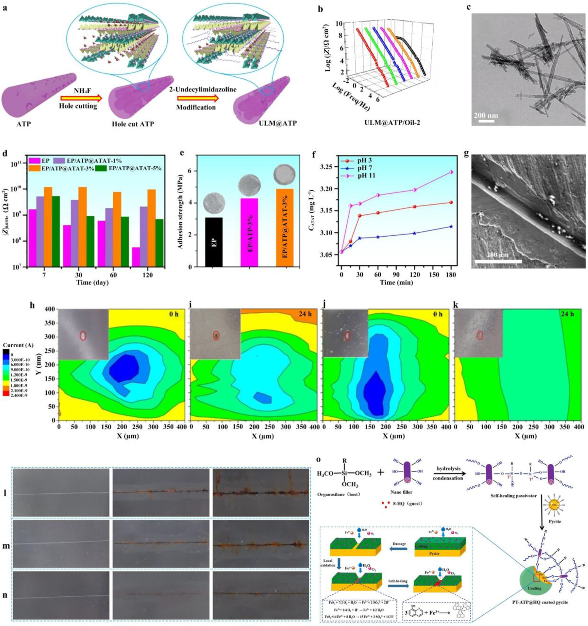
Research on ATP-based micro/nano-containers focuses on optimizing the porosity structure of ATP, regulating inhibitor release behaviour and elucidating the mechanisms of active corrosion protection (Thomas et al., Reference Thomas, Reshmy, Philip, Sindhu, Ulaet, Pugazhendhi and Awasthi2022; Udoh et al., Reference Udoh, Ekerenam, Daniel, Ikeuba, Njoku and Kolawole2024). For example, a ULM@ATP/Oil-2 (5.0 wt.% ULM@ATP in silicone oil; ULM = 2-undecylimidazoline) anti-corrosive coating was developed, and incorporating ULM@ATP composites was demonstrated to markedly improve the corrosion resistance of the coating (Fig. 7a; Wu et al., Reference Wu, Wei, Shi and Zhao2023b). Specifically, after 480 h of immersion in a 3.5 wt.% NaCl solution, the low-frequency impedance modulus (|Z|0.01Hz) of the ULM@ATP/Oil-2 coating remained as high as 1.62 × 10⁸ Ω·cm2 (Fig. 7b), approximately three orders of magnitude higher than that of the pure oil coating. Moreover, the introduction of ULM significantly improved the dispersion of ATP within the coating matrix. ATP particles, which originally exhibited a strong tendency to form sheet-like aggregates, were effectively dissociated after ULM loading, resulting in a more uniform and well-dispersed microstructure (Fig. 7c).
(a) Schematic illustration of the synthesis of ULM@ATP. (b) |Z|0.01Hz of the ULM@ATP/Oil-2 coating after 480 h of immersion in 3.5 wt.% NaCl solution. (c) Transmission electron microscopy image of ULM@ATP (Wu et al., Reference Wu, Wei, Shi and Zhao2023b). (d) |Z|0.01Hz values of various composite coatings. (e) Pull-off adhesion strengths of various composite coatings. (f) pH-responsive release profile of ATP@ATAT. (g) SEM image of the peeled EP/ATP@ATAT-3% coating after 96 h of immersion in 3.5 wt.% NaCl solution (Ali et al., Reference Ali, Shi and Jan2026). (h–k) SECM maps of (h,i) a defective blank coating and (j,k) an assembled ATP coating on carbon steel immersed in electrolyte solution (Liu et al., Reference Liu, Zhang, Hou, Pan, Zhao and Hou2018b). (l–n) Photographs of coatings after salt spray testing: (l) pure EP, (m) ATP/EP and (n) ATP@IL/EP (Ci et al., Reference Ci, Zhao and Gao2022). (o) Schematic illustration of the passivation and self-healing mechanism of PT-ATP@HQ for pyrite (Yu et al., Reference Yu, Feng, Yang, Dang and Zhang2022). HQ: 8-hydroxyquinoline (corrosion inhibitor); PT = organosilane passivator (Prop-SH/TEOS).

Figure 7 Long description
Multi-panel infographic summarizing synthesis, characterization and corrosion performance of ATP-based smart coatings. Panels a–k, arranged top-left to bottom-right, illustrate the following: Schematic of ATP synthesis and modification with 2-undecylimidazoline, forming ULM@ATP. Graph showing low-frequency impedance modulus (|Z|) over time for ULM@ATP/Oil-2 coating, indicating sustained impedance after immersion. Transmission electron microscopy image of ULM@ATP, displaying dissociated sheet-like aggregates. Bar graph comparing pull-off adhesion strengths, highlighting the highest strength for ATP@ATAT coatings. Line graph of pH-responsive release profile of ATP@ATAT, showing faster release at lower pH levels. SEM image of peeled EP/ATP@ATAT-3 percent coating after immersion in NaCl solution, revealing surface changes. SECM maps of current distribution for defective blank and assembled ATP coatings on carbon steel, demonstrating improved current distribution in ATP coatings. Photographs of coatings after salt spray testing: pure EP, ATP/EP and ATP@IL/EP, showing less rust for modified coatings. Schematic illustration of passivation and self-healing mechanism of PT-ATP@HQ for pyrite, detailing chemical reactions and inhibitor release. Abbreviations: EP (epoxy), IL (ionic liquid), SECM (scanning electrochemical microscopy), SEM (scanning electron microscopy), TEM (transmission electron microscopy), PT (organosilane passivator), HQ (8-hydroxyquinoline), ATP@ATAT (ATP-based coating).
Building on this concept, ATP was successfully loaded with 3-amino-1,2,4-triazole-5-thiol (ATAT) to construct inhibitor-containing nanofillers (ATP@ATAT), which were then incorporated into an epoxy matrix to provide both active and passive corrosion protection for metallic substrates (Ali et al., Reference Ali, Shi and Jan2026). Electrochemical impedance spectroscopy demonstrated that the |Z|0.01Hz of the composite coating containing 3 wt.% ATP@ATAT reached as high as 7.6 × 10⁹ Ω·cm2 after 120 days of immersion, nearly two orders of magnitude higher than that of the neat epoxy coating (5.69 × 10⁷ Ω·cm2), indicating a substantially improved barrier effect (Fig. 7d). The adhesion strength of the epoxy coating containing 3 wt.% ATP@ATAT was significantly improved from 3.10 to 4.95 MPa (Fig. 7e). Furthermore, the ATP@ATAT system exhibited pH-responsive release behaviour (Fig. 7f), enabling rapid and controlled release of ATAT under alkaline conditions associated with localized corrosion, thereby highlighting its strong potential for self-healing protective coatings. SEM images revealed that, after scratch immersion, the EP/ATP@ATAT-3% coating exhibited the least loss of surface integrity, demonstrating that the active protection endowed by the ATP@ATAT composite effectively suppressed the corrosion process and restrained the growth of corrosion products (Fig. 7g). This corrosion protection mechanism can be attributed to the synergistic effect of ATP nanofillers and the released ATAT passivating the damaged region.
A pH-responsive ATP nanocontainer was developed in which BTA was loaded via a layer-by-layer self-assembly strategy (Liu et al., Reference Liu, Zhang, Hou, Pan, Zhao and Hou2018b). For the scratched epoxy coating incorporating the assembled ATP nanoparticles, the scanning electrochemical microscopy (SECM) probe current at the defect increased from 0.3 to 1.2 nA with increasing immersion time (Fig. 7j,k), markedly higher than that recorded for the scratched epoxy coating without assembled ATP nanoparticles (Fig. 7h,i). This increased current indicates a reduction in corrosion activity within the scratched area, attributed to the release of BTA from the assembled ATP, which formed an adsorbed protective layer on the metal surface and thereby suppressed corrosion kinetics.
In another study, an ATP@IL/EP (IL = 1-allyl-3-octylimidazolium bromide; EP = epoxy) coating was prepared and tested for its salt spray performance (Ci et al., Reference Ci, Zhao and Gao2022). Following the ASTM B117 standard, coating samples with an artificial scratch of ∼10 cm in width were exposed to a neutral salt spray environment. After 7 and 14 days of exposure, the ATP@IL/EP coating (Fig. 7l–n) exhibited significantly better corrosion resistance than the reference samples, demonstrating excellent anticorrosion performance. Regardless of the type of ATP-based micro/nano-container, the underlying corrosion protection mechanism (Yu et al., Reference Yu, Feng, Yang, Dang and Zhang2022) involves the release of corrosion inhibitors to passivate defect sites (Fig. 7o).
This discussion clearly demonstrates that ATP-based anticorrosion coatings significantly improve both corrosion protection performance and damage-induced self-healing ability through the synergistic coupling of physical barrier action and triggered inhibitor release-induced interfacial passivation. Nevertheless, the development of ATP-based micro/nano-container anticorrosion coatings still faces three major challenges. First, precise regulation of micro/nano-container loading capacity and release kinetics remains to be achieved. Second, the long-term service stability of such coatings under multi-field coupled environments (e.g. salt spray, ultraviolet irradiation and freeze–thaw cycling) requires systematic evaluation. Third, the engineering compatibility of green corrosion inhibitor systems with waterborne or solvent-free processes needs further improvement.
Future research should pursue deeper interdisciplinary integration. On the one hand, in situ electrochemical characterization combined with molecular dynamics simulation should be employed to elucidate the dynamic interaction mechanisms at the ATP–inhibitor–metal interface. On the other hand, multi-stimuli-responsive release systems triggered by Cl–, pH and temperature should be developed to improve environmental specificity and response precision for intelligent protection. In parallel, the green integration of bio-based corrosion inhibitors with environmentally friendly resin systems should be actively promoted to accelerate the development of ATP-based anticorrosion coatings towards higher performance, greater intelligence and improved sustainability.
Anti-bacterial/anti-fouling coating
ATP, endowed with a distinctive one-dimensional nanorod architecture, tuneable surface chemistry and high SSA, exhibits exceptional proficiency in immobilizing nanoparticles and small organic molecules (Galán et al., Reference Galán, Mesa and Sánchez1994; Lei et al., Reference Lei, Wei, Wang, Su, Xue, Li and Hu2017; Zhong et al., Reference Zhong, Mu, Zhang, Hui, Kang and Wang2020; Gao et al., Reference Gao, Mu, Yang, Li and Wang2024; Liu et al., Reference Liu, He, Zhang, Tian, Liu and Zhu2025), establishing itself as a highly promising platform for engineering high-performance, intelligent anti-bacterial/anti-fouling coatings. ATP not only facilitates superhydrophobicity for bacterial anti-adhesion through micro/nano-hierarchical structuring combined with low-surface-energy modification (Hizal et al., Reference Hizal, Rungraeng, Lee, Jun, Busscher, van der Mei and Choi2017; Li et al., Reference Li, Wu, Chen, Nan, Jin, Sun and Wang2018; Liu et al., Reference Liu, Wang and Hou2021; Zhan et al., Reference Zhan, Yu, Amirfazli, Rahim Siddiqui and Li2022; Wu et al., Reference Wu, Wei, Shi and Zhao2023b) but also functions as an efficient micro/nano-container for the controlled release of anti-bacterial agents. Critically, its sharp nanorod morphology confers a chemical reagent-independent physical bactericidal capability. The synergistic interplay of these three mechanisms – physical barrier, sustained release and mechanical disruption – significantly enhances both protective efficacy and environmental sustainability.
Current research on ATP-based anti-bacterial composites predominantly explores two pathways: (1) ATP composites with metal ions (Ag+, Cu2+ and Zn2+) and metal oxides demonstrate long-lasting anti-bacterial activity and stability for releasing metal ions, achieving the dual functionality of bacterial inhibition and adsorption (Zhao et al., Reference Zhao, Zhou and Liu2006; Huo & Yang, Reference Huo and Yang2010; Yang et al., Reference Yang, Gu, Qian, Jiang and Du2011); and (2) ATP loaded with anti-bacterial agents (e.g. quaternary ammonium compounds, quaternary phosphonium salts, benzophenone derivatives, imidazolidinyl urea, pyrithione-based compounds and natural phenolic compounds) enables the controlled release of anti-bacterial agents and achieves increased biocidal efficiency (Cai et al., Reference Cai, Zhang, Ouyang, Ma, Tan and Peng2013).
Numerous studies (Zhao et al., Reference Zhao, Zhou and Liu2006; Huo & Yang, Reference Huo and Yang2010; Yang et al., Reference Yang, Gu, Qian, Jiang and Du2011; Cai et al., Reference Cai, Zhang, Ouyang, Ma, Tan and Peng2013; Zhong et al., Reference Zhong, Mu, Zhang, Hui, Kang and Wang2020; Jiang et al., Reference Jiang, Geng, Peng, Ni, Pei and Ye2024; Liu et al., Reference Liu, He, Zhang, Tian, Liu and Zhu2025) have reported the utilization of ATP as a support matrix for the incorporation of organic or inorganic biocides in the formulation of anti-bacterial and anti-fouling coatings. For organic anti-bacterial agents, Zhong et al. (Reference Zhong, Mu, Zhang, Hui, Kang and Wang2020) developed a green and facile strategy to load carvacrol (CAR) – a natural essential oil – onto ATP to obtain CAR/ATP via mechanical milling. The CAR/ATP exhibited a high loading capacity (23.00%) and sustained release behaviour, effectively overcoming the volatility and low solubility of CAR. The CAR/ATP anti-bacterial materials demonstrated effective anti-bacterial activity against both Escherichia coli and Staphylococcus aureus, with a minimum inhibitory concentration (MIC) of 2.0 mg mL–1. This work highlights the potential of ATP as a micro/nano-container for natural, low-toxicity anti-bacterial agents, which is particularly advantageous for environmentally benign anti-fouling coatings requiring long-term controlled release.
Liu et al. (Reference Liu, He, Zhang, Tian, Liu and Zhu2025) used ATP as a micro/nano-container to immobilize anti-bacterial components (dodecyl glycoside quaternary ammonium salt; APGQAS) through its strong adsorption capacity. Subsequently, copper tannate (CuTA) was in situ synthesized on the modified ATP and incorporated into Paraloid B72 to form the CuTA/APT@APGQAS/B72 composite coating. Anti-bacterial tests showed that at a concentration of 2 mg mL–1, this coating achieved inhibition rates of 99.99% against E. coli and 98.76% against S. aureus. The composite coating with 4 wt.% nanofiller reached 99.98% anti-bacterial efficiency against E. coli, and at 5 wt.% loading it reached over 99% inhibition against S. aureus. The synergistic anti-bacterial mechanisms involve the released Cu2+ disrupting bacterial membranes, tannic acid-derived polyphenols inducing oxidative stress and blocking metabolism and surface-grafted quaternary ammonium salts damaging cell walls.
Addressing the dual challenges of bacterial contamination and biofouling, the integration of ‘passive anti-adhesion + active anti-bacterial’ strategies has emerged as a cornerstone of green anti-fouling design. A previous study pioneered a bifunctional filler system using ATP as the structural scaffold: PSF (silica-decorated ATP) and FTAP (tannic acid-mediated Ag nanoparticle-anchored ATP) were co-dispersed in fluorosilicone resin to fabricate the FPFTS superhydrophobic anti-bacterial coating (Fig. 8a; Jiang et al., Reference Jiang, Geng, Peng, Ni, Pei and Ye2024). Quantitatively, bacterial adhesion of E. coli and S. aureus was reduced by 79.7 ± 6.2% and 81.9 ± 2.0%, respectively, compared to the blank sample (Fig. 8b,d), while inactivation rates reached 100.0 ± 0.1% and 99.8 ± 0.1%, respectively (Fig. 8c,e), attributable to the synergy of nanorod-induced membrane piercing and Ag+/reactive oxygen species (ROS)-mediated chemical eradication. Notably, the Cassie-state air film dynamically modulated Ag+ release kinetics (Fig. 8f), preventing burst release and minimizing ecological impact. Mechanistically, the coating unified passive defence (air film-mediated adhesion suppression and physical piercing) and active killing (Ag+-induced osmotic disruption, thiol protein inactivation, DNA interference and ROS-driven lipid peroxidation), establishing a reproducible blueprint for eco-friendly, intelligent anti-fouling systems (Fig. 8g–i).
(a) Schematic illustration of the fabrication process for the FPFTS coating. (b) Bacterial adhesion colonies on agar plates for various surfaces and (c) bacterial colonies on agar plates for various surfaces in anti-bacterial experiments. The numbers below the images denote colony-forming units (blue: E. coli; yellow: S. aureus). (d) Anti-adhesion performance of various material surfaces. (e) Anti-bacterial rates of various material surfaces. (f) Ag+ concentration in the soaking solution before and after wear resistance testing. (g) Schematic illustration of the passive defence mechanism of the FPFTS coating against bacteria. (h) Schematic illustration of the active anti-bacterial mechanism of the FPFTS coating. (i) Schematic illustration of the synergistic anti-bacterial mechanism of the superhydrophobic coating combining passive defence and active anti-bacterial strategies (Jiang et al., Reference Jiang, Geng, Peng, Ni, Pei and Ye2024). NP = nanoparticle.

Figure 8 Long description
Infographic detailing FPFTS coating. Top row: Schematic of fabrication process. Middle rows: Agar plate results show reduced colony-forming units for E. coli and S. aureus on FPFTS surfaces compared to others. Bar charts indicate high anti-adhesion and antibacterial rates for FPFTS. Line graph shows Ag concentration increases over time, with wear affecting release. Bottom row: Mechanism schematics illustrate passive defense with liquid air layer and active release with Ag nanoparticles and ROS. Icons differentiate live and dead bacteria, highlighting the coating′s dual strategy effectiveness.
Collectively, the role of ATP in anti-bacterial coatings has evolved far beyond that of a passive filler. In early-stage systems, ATP mainly served as a container for the immobilization and controlled release of biocidal agents. Subsequent studies increasingly exploited its intrinsic one-dimensional nanorod morphology to construct micro/nano-rough surfaces for anti-adhesion and to induce direct mechanical damage to bacterial membranes, thereby transforming ATP from a ‘supporting component’ into a ‘structure-enabled functional unit’. More recently, ATP has been further integrated into multifunctional nanozyme and catalytic sterilization systems, where its surface chemistry, interfacial charge characteristics and hierarchical architecture collectively regulate nanoparticle dispersion, ion-release behaviour and reactive species generation. This progression reflects a fundamental shift in ATP-based coating design: from simply incorporating anti-bacterial additives into a matrix towards deliberately engineering ATP as a multifunctional platform that couples surface topography, interfacial chemistry and bioactive response.
Future research should therefore move beyond empirical material combination and focus on three key directions: (1) precise control of ATP surface/interface chemistry; (2) quantitative understanding of the relationship between nanorod assembly and anti-bacterial performance; and (3) the development of stimuli-responsive ATP-based coatings capable of adaptive anti-fouling and on-demand sterilization under complex conditions. With these advances, ATP – as a naturally abundant and sustainable mineral nanomaterial – is expected to play an increasingly important role in next-generation, environmentally benign anti-bacterial and anti-fouling coatings.
Self-cleaning/anti-smudge coating
Self-cleaning/anti-smudge coatings are surface treatments capable of removing contaminants such as liquids, dirt, oil and other pollutants, thereby reducing surface smudging and facilitating easier cleaning. They generally achieve this by endowing the coating surface with superhydrophobicity, oleophobicity or superamphiphobicity – characteristics commonly obtained by constructing micro/nano-hierarchical structures and modifying rough surfaces with low-surface-energy substances (Ma & Hill, Reference Ma and Hill2006; Rao et al., Reference Rao, Latthe, Nadargi, Hirashima and Ganesan2009; Si & Guo, Reference Si and Guo2015; Yu et al., Reference Yu, Xiao, Ye and Pan2018; Wang et al., Reference Wang, Zhang, Yin, Jin, Liu, Li and Wang2019b, Reference Wang, Sun, Hokkanen, Zhang, Lin and Liu2020a, Reference Wang, Wang, Jiang, Ji, Liu, Tian and Zhang2024, Reference Wang, Wang, Wang and Zhang2025b; Hooda et al., Reference Hooda, Goyat, Pandey, Kumar and Gupta2020; Barthwal et al., Reference Barthwal, Jeon and Lim2022; Guo et al., Reference Guo, Guo, Fang, Wang, Liu and Pei2022; Wei et al., Reference Wei, Li, Tian, Zhang, Liang and Zhang2022; Butt et al., Reference Butt, Wang, Ma and Li2023; Li et al., Reference Li, Liang, Zhang and Zhang2023; Zhang et al., Reference Zhang, Liu, Zhan and Hou2024a).
An environmentally friendly and abrasion-resistant superhydrophobic anti-corrosion coating was prepared by doping hexadecyltrimethoxysilane (HDTMS)-modified ATP fillers in waterborne epoxy resin (Fig. 9a; Liu et al., Reference Liu, Zhan and Zhang2024). Copper chloride dihydrate, sand grains and silica powder were used as contaminants and uniformly dispersed on the surface of an inclined ATP@HDTMS@WEP (HDTMS-modified ATP as a filler combined with waterborne epoxy (WEP)) coating. Water droplets were then dropped onto the contaminated surface to observe their contaminant removal ability. The results indicated that all contaminants were removed without leaving water droplet traces (Fig. 9b). The self-cleaning mechanism of the ATP@HDTMS@WEP coating relies on its extremely low surface energy, which enables water droplets to roll off the surface, thereby removing surface contaminants. In addition, anti-smudge performance was further investigated using water, milk, tea and Coca-Cola. The ATP@HDTMS@WEP coatings were vertically dipped into the corresponding solutions for several seconds and then removed to observe surface contamination. After three repeated cycles, the surface remained clean and liquid non-wetting (Fig. 9c). These excellent anti-smudge and self-cleaning functions can be attributed to the air cushion present on the coating surface, which effectively decreases the contact area between liquids/solids and the coating.
(a) Schematic illustration of the fabrication process for modified ATP@HDTMS particles and the superhydrophobic ATP@HDTMS@WEP coating. (b) Self-cleaning performance of the superhydrophobic ATP@HDTMS@WEP coating against various solid contaminants and the corresponding self-cleaning mechanism. (c) Anti-smudge performance of the superhydrophobic ATP@HDTMS@WEP coating against various liquid contaminants (Liu et al., Reference Liu, Zhan and Zhang2024). (d) Schematic illustration of the fabrication process for OG-ATP particles and the superamphiphobic coating. (e) Water droplet (surface tension at 20°C: 72.8 mN m–1) and n-hexadecane droplet (surface tension at 20°C: 27.5 mN m–1) on OG-ATP particles. (f) Self-cleaning evaluation of the superamphiphobic OG-ATP coating driven by water and n-hexadecane. (g) CA and SA values of various liquid droplets on the superamphiphobic OG-ATP coating, along with its anti-smudge performance against various liquid contaminants of different surface tensions (Zhang et al., Reference Zhang, Liu, Jiang and Zhang2024b).

Figure 9 Long description
The composite image includes several panels detailing the fabrication and performance of coatings. (a) Schematic of the fabrication process for ATP@HDTMS particles and the superhydrophobic ATP@HDTMS@WEP coating, involving stirring, drying and spraying on aluminum alloy. (b) Self-cleaning performance against solid contaminants like copper chloride dihydrate, sand grains and silica powder, with a diagram illustrating the mechanism. (c) Anti-smudge performance against liquids such as water, milk, Coca-Cola and tea, showing clean surfaces after testing. (d) Schematic of the fabrication process for OG-ATP particles and superamphiphobic coating, including spraying and curing. (e) Images of water and hexadecane droplets on OG-ATP particles, showing contact angles. (f) Self-cleaning evaluation of the superamphiphobic OG-ATP coating with water and hexadecane. (g) Graph of CA and SA values for various liquids on the superamphiphobic coating, with images showing anti-smudge performance against different liquids.
To further improve self-cleaning/anti-smudge performance, a superamphiphobic coating was investigated (Zhang et al., Reference Zhang, Liu, Jiang and Zhang2024b). A filler co-modified with TEOS and 1H,1H,2H,2H-perfluorooctyltriethoxysilane (PFAS) was prepared (OG-ATP; Fig. 9d), yielding a superamphiphobic material (Fig. 9e). The superamphiphobic self-cleaning effect of the OG-ATP coating was investigated using water and n-hexadecane droplets. Copper sulfate pentahydrate contaminant was evenly sprinkled on the coating surface. The results showed that both water and n-hexadecane droplets could remove the contaminant from the sample surface (Fig. 9f). Furthermore, water and various oil droplets on the OG-ATP coating surface exhibited superamphiphobic characteristics (Fig. 9g). The anti-smudge performance of the OG-ATP coating was evaluated using water, glycerol, ethylene glycol, peanut oil and n-hexadecane (Fig. 9h). No liquid residue was observed on the OG-ATP coating surface for any of the test liquids, demonstrating excellent liquid repellency and low interfacial adhesion. This non-wettability and liquid repellency are attributed to the rough structure of the OG-ATP coating and the ultra-low surface energy imparted by organosilane modification.
Although ATP-based self-cleaning/anti-smudge coatings exhibit excellent contaminant removal through the incorporation of modified ATP fillers, several challenges remain to be addressed. First is their insufficient mechanical durability. The superamphiphobic characteristics of the coatings are imparted by micro/nano-structures on their surface, which are easily damaged and cannot ensure long-term effectiveness. Second are their environmental concerns and high cost. Fluorinated fillers pose adverse environmental effects and incur high costs, while fluorine-free alternatives still cannot meet practical application requirements due to their inferior performance or durability. Future research should focus on developing multifunctional coatings with eco-friendly and sustainable fillers, as well as cost-effective manufacturing methods, to meet the demands of self-cleaning/anti-smudge coatings under harsh conditions.
Anti-icing coating
Superhydrophobic coatings represent one of the most promising passive anti-icing strategies (Long et al., Reference Long, Yin, Mu, Wang, Hu and Li2020; Zhang et al., Reference Zhang, Liu, Zhan and Hou2024a,b, Reference Wang, Wang, Wang and Zhang2025b; Wang et al., Reference Wang, Liu, Xu, Zhang, Wang and He2025c). Their characteristics – high CA and low SA – reduce the solid–liquid contact area, thereby effectively delaying the icing process and diminishing ice adhesion strength (Kreder et al., Reference Kreder, Alvarenga, Kim and Aizenberg2016; Wang et al., Reference Wang, Tian, Jiang, Luo, Chen and Hu2022). The nanorod crystal structure of ATP provides a natural skeleton for constructing the micro/nano-scale rough topography required for superhydrophobic coatings. However, superhydrophobic anti-icing coatings can only delay icing; they cannot fundamentally prevent its occurrence. Once ice accumulates on the coating surface, the difficulty of de-icing becomes comparable to that of conventional coatings. Consequently, photothermal superhydrophobic coatings that integrate both passive anti-icing and active de-icing functionalities have emerged as an efficient and sustainable solution for ice prevention and removal (Jiang et al., Reference Jiang, Chen, Zhang and Huang2018; Cong et al., Reference Cong, Qin, Chen, Jin, Liu and Wang2023; Xie et al., Reference Xie, Tian, Shao, Wang, Chen, Zhu and Liao2023b).
Through suitable modification of ATP fillers, coatings can be endowed with excellent passive anti-icing and active de-icing functions. Several studies have indicated that modifying ATP with silane coupling agents or carbon materials imparts excellent superhydrophobic and photothermal properties (Xie et al., Reference Xie, Wei, Duan, Zhu, Yang and Chen2022; Mao et al., Reference Mao, Wei, Li, Li, Huang and Zhang2024b). A PPy/ATP@hexadecylPOS (PPy = polypyrrole; hexadecylPOS = hexadecyl polysiloxane) filler (Xie et al., Reference Xie, Wei, Duan, Zhu, Yang and Chen2022) was prepared through the oxidative polymerization of pyrrole on ATP, followed by modification with hexadecyl polysiloxane (Fig. 10a). Anti/de-icing coatings were then prepared by spray-coating a mixture of the PPy/ATP@hexadecylPOS filler and a silicone resin onto aluminium plates. The resulting coating exhibited superior superhydrophobicity, with a water CA of 162.7° and a SA of 2.7° (Fig. 10b). The coating demonstrated outstanding photothermal conversion efficiency: its surface temperature rapidly increased to 60.0°C after 1 min of irradiation, to 70.7°C after 3 min of irradiation and to 80.0°C after 10 min of irradiation – twice that of the pristine ATP coating (Fig. 10c). This rapid temperature rise facilitates the quick melting of transient ice layers, enabling active de-icing. Regarding passive anti-icing performance (in the dark, –10°C, 60% relative humidity), water droplets on bare aluminium completely froze in only 68 s, whereas those on the PPy/ATP@hexadecylPOS coating took nearly five times longer (330 s; Fig. 10d). For active anti-icing (1 sun, –10°C, 60% relative humidity), droplets on bare aluminium froze completely within 120 s, but freezing was delayed to 600 s on the coated aluminium (Fig. 10e), demonstrating exceptional photothermal conversion capability. The anti-icing mechanism of the coating arises from the synergistic effect between superhydrophobicity and the photothermal effect: (1) the three-level hierarchical micro/nano-structure and low surface energy significantly reduce the water–solid contact area and contact time via an insulating air cushion at the interface, thereby delaying the icing process and achieving efficient passive anti-icing; and (2) the PPy photothermal layer, supported by ATP, rapidly converts solar energy into thermal energy for active de-icing.
(a) Schematic illustration of the preparation process for PPy/ATP@hexadecylPOS photothermal superhydrophobic coatings. (b) SEM images and water CA of the PPy/ATP@hexadecylPOS coatings, showing a silicone resin-rich phase (red rectangles) and a PPy/ATP@hexadecylPOS-rich phase (yellow circle). (c) Surface temperature evolution of various coatings as a function of irradiation time under 1 sun illumination. (d,e) Water freezing time on bare and PPy/ATP@hexadecylPOS-coated aluminium sheets at –10°C under (d) dark conditions and (e) 1 sun irradiation (Xie et al., Reference Xie, Wei, Duan, Zhu, Yang and Chen2022). (f) Schematic illustration of the preparation process for SiP/F-MOFs@ATP coatings. (g) Transmission electron microscopy image of SiP/F-MOFs@ATP. (h) 3D profilometer image of the SiP/F-MOFs@ATP coating. (i) SA of the coating as a function of temperature after storage at low temperature and 80% relative humidity for 1 h. (j) Surface temperature of bare and coated aluminium alloy plates as a function of time under 1 sun irradiation at 25.4°C and 38% relative humidity. (k,l) De-frosting process on (k) bare and coated aluminium alloy plates and (l) cable lines in a –10°C and 80% relative humidity environment under 0.1 sun irradiation (Mao et al., Reference Mao, Wei, Li, Li, Huang and Zhang2024b).

Figure 10 Long description
Schematic illustration of the preparation process for PPy/ATP@hexadecylPOS photothermal superhydrophobic coatings, showing steps from ATP to the final coating. SEM images display the coating′s structure with a water contact angle of 162.7 degrees. A graph shows surface temperature evolution of various coatings under 1 sun illumination over time. Water freezing time on bare and coated aluminium sheets is compared under dark and 1 sun irradiation conditions. Another schematic illustrates the preparation process for SiP/F-MOFs@ATP coatings, detailing microstructure and light trap formation. Transmission electron microscopy image of SiP/F-MOFs@ATP is shown. A 3D profilometer image of the coating is included. A graph shows SA of the coating as a function of temperature after storage at low temperature and 80 percent relative humidity. Surface temperature of bare and coated aluminium alloy plates is graphed over time under 1 sun irradiation. De-frosting process on bare and coated aluminium alloy plates and cable lines is depicted under 0.1 sun irradiation in a cold, humid environment.
Similarly, a photothermal superhydrophobic coating (SiP/F-MOFs@ATP; SiP = silicone-modified polyester; F-MOFs = fluorinated MOFs) featuring a three-level micro/nano/nano-hierarchical structure based on ATP nanorods has been reported (Fig. 10f; Mao et al., Reference Mao, Wei, Li, Li, Huang and Zhang2024b). The morphology of F-MOFs@ATP is shown in Fig. 10g. The coating exhibited a surface roughness of 1.83 μm (Fig. 10h) and a water CA of 165.6°. The SiP/F-MOFs@ATP coating maintained good superhydrophobicity under low-temperature and high-humidity conditions. Even at –20°C or –30°C with 80% relative humidity for 1 h, the coating remained superhydrophobic, although the SA increased (Fig. 10i). The coating exhibited excellent photothermal performance, reaching 101°C within 8 min under 1 sun illumination (25.4°C, 38% relative humidity; Fig. 10j), outperforming most reported photothermal superhydrophobic coatings. The superhydrophobic nature and low thermal conductivity of the coating prolonged the water droplet freezing time from 53 s on bare aluminium to 640 s at –10°C and 80% relative humidity. Under weak light (0.1 sun), the photothermal effect of the MOFs elevated the coating surface temperature from –13.3°C to +6.1°C, causing de-iced water droplets to rapidly roll off under low ice adhesion (36.3 kPa). Furthermore, under identical conditions, the coating enabled complete melting and roll-off of a frost layer (∼0.8 mm) on a 20° inclined surface within 16.7 min, whereas no melting was observed on the control sample even after 60 min (Fig. 10k). The defrosting time for a coated cable was also significantly reduced from >60 min for the bare cable to 20.5 min (Fig. 10l). This coating demonstrates excellent comprehensive performance in both simulated and outdoor environments characterized by low temperature, high humidity and weak light, highlighting the practical application potential of ATP nanorods for constructing high-performance photothermal superhydrophobic anti-icing systems.
From the perspective of anti-icing mechanisms, ATP-based coatings achieve ice prevention and removal primarily through two mechanisms: (1) a passive anti-icing mechanism, leveraging the superhydrophobic micro/nano-structure to prolong droplet freezing time and reduce ice adhesion strength; and (2) an active de-icing mechanism, wherein loaded photothermal materials convert solar energy into thermal energy for rapid ice melting, capable of raising the coating surface temperature above the freezing point even under weak light conditions.
Despite significant progress having been achieved in current research, the practical application of ATP-based anti-icing coatings still faces three major challenges. First, regarding fluorine-free strategies, eliminating fluorine-containing materials while maintaining excellent hydrophobicity remains a key objective. Second, concerning long-term service stability, the mechanisms governing performance retention under complex outdoor conditions (e.g. freeze–thaw cycles, ultraviolet irradiation and mechanical abrasion) require in-depth investigation. Third, with respect to extreme environment adaptability, anti-icing efficacy under more severe conditions (lower temperature, higher humidity and weaker light) needs further enhancement. If future research can effectively synergize material design, structural regulation and long-term service evaluation, ATP-based anti-icing coatings hold promise as an ideal solution for addressing ice accumulation issues under complex climatic conditions.
Conclusions, challenges and perspectives
This review systematically summarizes recent progress in ATP-based multifunctional protective coatings. Starting from the intrinsic structural characteristics of ATP – including its rod-like morphology, channel structure and surface activity – the review discusses how different pretreatment strategies regulate its microstructure, pore characteristics, surface chemistry, dispersibility and compatibility with coating matrices. On this basis, the review further summarizes the multifunctional roles of ATP in coating systems and the corresponding protective mechanisms. ATP can act as: (1) a barrier-phase filler to improve the coating density; (2) a micro/nano-container for loading and releasing active agents; and (3) a structural unit for constructing surface roughness and regulating interfacial properties. According to these roles, the applications of ATP-based coatings in anti-corrosion/self-healing, superhydrophobicity, self-cleaning/anti-smudge, anti-icing and anti-bacterial/anti-fouling systems are discussed. Through these aspects, this review aims to clarify the relationships between ATP pretreatment, coating construction and final functional performance and to provide a reference for the design of high-performance multifunctional protective coatings.
Despite considerable progress having been achieved to date, several key issues still constrain the further development of ATP-based multifunctional coatings:
(1) Insufficient understanding of the structure–property relationship. The relationship between pretreatment conditions and the structural evolution of ATP remains inadequately understood. Variations in channel accessibility, surface active sites, aggregation state and interfacial bonding directly influence barrier capability, active agent loading and release and long-term durability. However, these correlations are still largely described in qualitative terms. A more quantitative understanding of the structure–interface–performance relationship is essential to establishing general design principles.
(2) Limited functional integration. Current functionalization strategies primarily aim to improve dispersion and matrix compatibility or to introduce a single target function, while deeper integration between ATP and coating matrices remains limited. Future modification routes should not only strengthen interfacial stability but also endow ATP with more controllable and programmable functionalities.
(3) Unclear synergistic and competitive relationships among functions. Although multifunctionality has become a major development trend, the synergistic and competitive relationships among different functions remain unclear in many systems. For instance, roughness construction, active agent loading, wettability regulation and mechanical robustness do not necessarily evolve synergistically. Without a clear understanding of these coupling effects, multifunctional integration may increase structural complexity without delivering proportional gains in service performance.
Addressing these challenges will require a paradigm shift from empirical materials design towards a quantitative, mechanism-driven understanding of ATP-based coating systems. Future research should prioritize the development of high-throughput characterization and computational modelling approaches to establish predictive structure–property correlations, as well as the design of smart ATP architectures with stimuli-responsive and self-regulating functionalities. Furthermore, it is critical to recognize that current progress has been largely confined to laboratory-scale demonstrations under idealized conditions. To bridge the gap between fundamental research and industrial practical application, subsequent studies must be strategically aligned with real-world industrial production parameters, including considerations of scalability, process stability, cost-effectiveness and long-term performance under complex operational environments. With such advances, ATP – as an abundant, cost-effective and environmentally compatible nanoclay – holds great promise for enabling next-generation protective coatings with integrated, durable and application-adaptive performance.
CRediT authorship contribution statement
Qiaozhi Miao: Methodology, Writing – original draft, Writing – review & editing. Chaoyu Zhang: Writing – review & editing, Formal analysis, Software. Wenbo Wang, Yue Yin, Mei Wu: Conceptualization, Writing – review & editing, Resources, Supervision.
Financial support
This research was supported by the following projects: the National Natural Science Foundation of China (52561021; 22468033); the Natural Science Foundation of Inner Mongolia Autonomous Region (2024SHZR1554); the Key R&D and Achievement Transformation Project of Inner Mongolia Autonomous Region (2023YFHH0057); Jiangsu Provincial Key Laboratory of Palygorskite Science and Applied Technology, Huaiyin Institute of Technology (HPK202302); and the Program of Higher-Level Talents of Inner Mongolia University (10000-23112101/017).
Competing interests
The authors declare that they have no known competing financial interests or personal relationships that could have appeared to influence the work reported in this paper.