1. INTRODUCTION
In many high-energy and high-power laser systems, such as inertial confinement fusion drivers, require the propagation of many high-power laser beams over long paths in air. The product of the laser intensity times and the air-interaction length will be very large, resulting in the generation of certain nonlinear optical processes, such as stimulated rotational Raman scattering (SRRS), which seriously limits the laser intensity and fluence that can be transmitted through the air (Mack et al., Reference Mack, Carman, Reintjes and Bloembergen1970; Henesian et al., Reference Henesian, Swift and Murray1985; Leung et al., Reference Leung, Oron, Klimek, Holmes and Flusberg1988; Ying et al., Reference Ying, Kessler and Lawrence1994). Therefore, the SRRS process suppression turns to be one of the key problems that have to be solved in the application and transmission of the high-energy and high-power laser.
Skeldon etc. have pointed out that smoothing by spectral dispersion (SSD) can suppress the SRRS process (Skeldon & Bahr, Reference Skeldon and Bahr1991; Fan et al., Reference Fan, Lu, Lin, Yang, Liu, Dong, Zhu and Hasi2013), however, SSD will destroy the quality and the coherence of laser beam. National Ignition Facility (NIF) shortens the transmission distances of fundamental frequency and frequency-tripled laser pulses in air by replacing part of air with inert gas and decreasing the intervals of the final optics assemblies respectively (Kurnit et al., Reference Kurnit, Shimada, Sorem, Taylor, Rodriguez, Clement, Fearn, James and Milonni1997; Hunt, Reference Hunt2000; Wegner et al., Reference Wegner, Auerbach, Biesiada, Dixit, Lawson, Menapace, Parham, Swift, Whitman and Williams2004); however, the schemes are very hard to implement, increasing the cost and even bring new physical problems. Wang et al. have shown the scheme that using transmitting Bragg volume grating to inhibit SRRS by filtering out Stokes light from laser (Wang et al., Reference Wang, Zhang, Han, Li, Zhou, Feng and Xiang2011), but the high intensity of the driven laser and the tiny SRRS frequency shift in air will bring a great challenge to grating fabrication, especially for the broad-band laser pulses.
In this paper, we propose a new, simple, and effective method to suppress SRRS using wave plate and polarizer. The detailed work is given by simulation and analysis in the rest of this paper as follows. In Sections 2 and 3, the basic principle of the suppression scheme and the related theories are given, and the design process of the scheme is shown in Section 4. In the last section, the concluding remarks summarize the paper briefly.
2. BASIC PRINCIPLE
In SRRS process, the Stokes light is also linearly polarized if the incident laser is linearly polarized, and they have the same polarization directions (Leung et al., Reference Leung, Oron, Klimek, Holmes and Flusberg1988). The SRRS gain will decrease if the polarization direction of Stokes light deviates from that of laser, and down to zero when their polarization directions are perpendicular. Based on this phenomenon, we propose a new method of suppressing the SRRS gain and increasing the transmission efficiency of the high-energy and high-power laser pulses by controlling the Stokes light polarization direction.
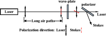
The scheme of the method is shown in Figure 1, one assembly of wave plate and polarizer is inserted in the place where a certain amount of Stokes light generates. The wave plate is a full-wave plate for the laser and half-wave plate for the Stokes light, passing through which the polarization direction of the Stokes light is rotated by 90° while that of the laser is unchanged, then the Stokes light is filtered out from the laser by the polarizer, whose direction of the transmission axis is parallel to the polarization direction of the laser. Therefore, the laser energy loss caused by the amplification of Stokes light slows down when the laser pulse propagates further. The high-energy and high-power laser pulse can propagate farther effectively if inserting more assemblies of wave plates and polarizers in the path.
The schematic diagram.

3. THEORETICAL ANALYSIS
When the laser and the Stokes light are incident on the wave plate perpendicularly, the wave vector endpoints of the transmitted lights follow the following locus equation:
 $${\left( {\displaystyle{{{E_{0i}}} \over {{A_{{\rm o}i}}}}} \right)^2} + {\left( {\displaystyle{{{E_{{\rm e}i}}} \over {{A_{{\rm e}i}}}}} \right)^2} - 2\displaystyle{{{E_{{\rm o}i}}{E_{{\rm e}i}}} \over {{A_{{\rm o}i}}{A_{{\rm e}i}}}}\cos {{\rm\varphi} _i} = {\sin ^2}{{\rm\varphi} _i}, $$
where i = L, S represent the laser and the Stokes respectively, A oi, A ei are the amplitudes of the “o” light and the “e” light respectively at the incident plane of the wave plate, E oi, E ei are the electric field components of the “o” light and the “e” light at the exit plane of the wave plate, φi are the phase delay of the transmitted laser and Stokes light, they can be derived as
 $${{\rm\varphi} _{\rm L}} = \displaystyle{{2\pi} \over {{{\rm\lambda} _{\rm L}}}}d\Delta {n_{\rm L}} = 2{m_1}{\rm\pi} {\rm,} {m_1} = 1,2, \ldots, $$
 $${{\rm\varphi} _{\rm S}} = \displaystyle{{2{\rm\pi}} \over {{{\rm\lambda} _{\rm S}}}}d\Delta {n_{\rm S}} = (2{m_2} + 1){\rm\pi}{\rm,}\ {m_2} = 0,1,2, \ldots, $$
where λL and λS are the wavelengths of the laser and the Stokes; d is the thickness of the wave plate; Δn L and Δn S are the birefringences of the wave plate for laser and Stokes, respectively. From Eq.s (2) and (3), it can be derived that
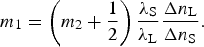 $${m_1} = \left( {{m_2} + \displaystyle{1 \over 2}} \right)\displaystyle{{{{\rm\lambda} _{\rm S}}} \over {{{\rm\lambda} _{\rm L}}}}\displaystyle{{\Delta {n_{\rm L}}} \over {\Delta {n_{\rm S}}}}. $$
Apparently, m 1 > m 2 for λS > λL and Δn L > Δn S. Defining
 $${m_1} = {m_2} + k,\;\;\;k = 1,2, \ldots $$
then
 $${m_1} = \displaystyle{{{{\rm\lambda} _{\rm S}}\Delta {n_{\rm L}}} \over {{{\rm\lambda} _{\rm S}}\Delta {n_{\rm L}} - {{\rm\lambda} _{\rm L}}\Delta {n_{\rm S}}}}\left( {k - \displaystyle{1 \over 2}} \right) $$
and the thickness of the wave plate is
 $$d = \displaystyle{{{{\rm\lambda} _{\rm S}}{{\rm\lambda} _{\rm L}}} \over {{{\rm\lambda} _{\rm S}}\Delta {n_{\rm L}} - {{\rm\lambda} _{\rm L}}\Delta {n_{\rm S}}}}\left( {k - \displaystyle{1 \over 2}} \right). $$
The wave plate with the thickness of d is exactly full wave plate for the laser and half wave plate for the Stokes only when m 1 is an integer. Otherwise, the transmitted laser and Stokes light will be depolarized and their ellipticity (minor-to-major axis ratio) can be derived from Eq. (1)
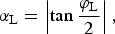 $${{\rm\alpha} _{\rm L}} = \left\vert {\tan \displaystyle{{{{\rm\varphi} _{\rm L}}} \over 2}} \right\vert, $$
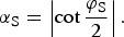 $${{\rm\alpha} _{\rm S}} = \left\vert {\cot \displaystyle{{{{\rm\varphi} _{\rm S}}} \over 2}} \right\vert. $$
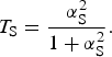
Due to the very tiny frequency shift (<100 cm−1) of SRRS in air, we assume that the polarizer behind the wave plate has the same effects on the laser and the Stokes light. When the direction of the polarizer's transmission axis is parallel to the polarization direction (or the principal axes of ellipses) of the laser and perpendicular to that of Stokes, the transmittances of the laser and the Stokes light through the polarizer can be calculated respectively as
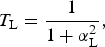 $${T_{\rm L}} = \displaystyle{1 \over {1 + {\rm\alpha} _{\rm L}^{\rm 2}}}, $$
 $${T_{\rm S}} = \displaystyle{{{\rm{\rm\alpha}}_{\rm S}^{\rm 2}} \over {1 + {\rm\alpha} _{\rm S}^2}}. $$
4. SCHEMATIC DESIGN
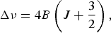
The SRRS shift in air is (Skeldon & Bahr, Reference Skeldon and Bahr1991)
 $$\Delta {\rm\nu} = 4B\left( {J + \displaystyle{3 \over 2}} \right), $$
where B is the rotational constant and equals 2 cm−1 for air (or nitrogen), J is the rotational quantum number. Here, we assume that the Stokes light only refers to the spectral line S(8) which has the maximum gain coefficient, the central wavelength of laser is 351 nm, and the wave plate is made of quartz.
4.1. Narrowband Laser
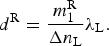
For the central wavelength of 351 nm, the values of m 1 derived from Eq. (6) are usually not integers, which means that the transmitted laser and Stokes through the wave plate with thickness of d derived from Eq. (7) will depolarized, thus their transmittances through the polarizer T L < 1, T S > 0. We round m 1
 $$m_{\rm 1}^{\rm R} = {\rm round} {\rm (}{m_1}{\rm )}, $$
and the corresponding thickness of the wave plate is
 $${d^{\rm R}} = \displaystyle{{m_{\rm 1}^{\rm R}} \over {\Delta {n_{\rm L}}}}{{\rm\lambda} _{\rm L}}. $$
The polarization state of the laser remains unchanged (ellipticity αLR = 0), while the Stokes light will be depolarized (αSR ≠ 0) after passing through the wave plate with the thickness of d R, then their transmittances through the polarizer T LR = 1, T SR > 0. Apparently, the thickness d R compared with d of the wave plate is the better choice for us if T SR < T S.
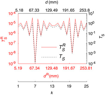
The variations of the transmittances T SR and T S of the Stokes passing through the assembly of wave plate and polarizer with k (d R, d) are calculated, respectively, as shown in Figure 2. From Figure 2 we can see that, with the increasing of k (1–25), the transmittances T SR, T S of the Stokes are turbulent and come to extreme points at the same values of k, meanwhile, T SR is less than T S (T SR ≪ T S), so the thickness d R is the better choice compared with d. The polarizer has the minimal transmittance of 1.20 × 10⁻⁹ when k = 7, which corresponds to the thickness d R of 67.34 mm. However, we have to notice that the thicker the wave plate is, the more sensitive to environment (such as temperature) changes, the more unstable the assembly will be. Therefore we choose the minimum thickness d R of 5.19 mm (k = 1) in our design, the corresponding transmittance of the Stokes passing through the assembly of wave plate and polarizer equals 6.20 × 10⁻⁶.
The variations of the transmittances T SR and T S of the Stokes with k (d R, d).

Once the thickness of wave plate is given, the other important issue is calculating how many the assemblies of wave plates and polarizers will be utilized and where they will be located. Here, we define the generation threshold of SRRS where the energy of the Stokes light reaches to 1% of that of the initial laser or to say the Stokes conversion efficiency ηS reaches to 1%, and the corresponding transmission length of the laser is defined as SRRS threshold distance. From Eqs (1)–(3) of reference (Ying et al., Reference Ying, Kessler and Lawrence1994), we can calculate the threshold distance of SRRS in air is 16.2 m for the flat-topped laser pulse of 351 nm, 2 GW/cm2 and 3 ns when the SRRS gain coefficient equals 6.76 cm/TW (Ying et al., Reference Ying, Kessler and Lawrence1994), the Stokes conversion efficiency ηS will rise to 80% if the laser pulse travels to 30.0 m. Now, we lengthen the SRRS threshold distance of 16.2–30.0 m using the assemblies of wave plates and polarizers.
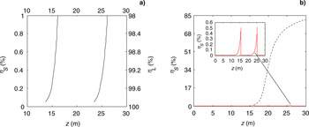
Insert one assembly of wave plate and polarizer in the places where once the Stokes conversion efficiency rises to ηS, such as shown in Figure 1, until the high-power laser pulse traveling path reaches to 30.0 m. It can be deduced that the conversion efficiency ηS at the incident plane of the wave plate, the location and the number of the assembly are determined by the expected transmission efficiency (or remaining ratio) ηL of the laser pulse in the terminal position of 30.0 m. In Figure 3a, the simulation result shows how the laser pulse transmission efficiency ηL and the Stokes conversion efficiency ηS (0.5‰~1%) vary with the location z of assemblies. From Figure 3a, it can be seen that if we expect the transmission efficiency ηL of the laser pulse exceeding 98.0%, two assemblies have to be inserted in the transmission paths, ηL will increase gradually as the two assemblies approach to the initial position (z = 0), and rise to 99.0% when the two assemblies are placed at the locations of 15.6 and 25.5 m, respectively, where the Stokes conversion efficiency ηS at the incident plane of the wave plate is 0.5%. In this case, Figure 3b shows how the Stokes conversion efficiencies ηS vary with the transmission distance z: The solid line corresponds to the situation of using two assemblies and the dash line corresponds to that of no assembly used. It is thus clear that the suppression efficiency of the assemblies of wave plates and polarizers on SRRS is very high.
(a) The variation of the laser pulse transmission efficiency ηL and the Stokes conversion efficiency ηS at the incident plane of the wave plate with the location z of the assembly. (b) The variation of the Stokes conversion efficiency ηS with the transmission distance z before (dotted curve) and after (solid curve) using the assemblies.

4.2. Broadband Laser
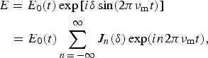
Currently, in some large-scale laser systems, such as OMEGA and NIF (Skeldon & Bahr, Reference Skeldon and Bahr1991; Dixit, Reference Dixit1992) to suppress harmful nonlinear effects or improve laser irradiation uniformity in far field, phase modulation is usually used to broaden the laser bandwidth. Using the slowly varying amplitude approximation, the electric field of the phase modulation broadband laser pulse can be expressed as
 $$\eqalign{& E = {E_0}(t)\exp \left[ {i{\rm\delta} \sin (2{\rm\pi}{{\rm\nu} _{\rm m}}t)} \right] \cr & \;\;\; = {E_0}(t)\sum\limits_{n \,= \,- \infty} ^\infty {{J_n}({\rm\delta} )} \exp (in2{\rm\pi}{{\rm\nu} _{\rm m}}t),} $$
where, E 0(t) is the real amplitude of the laser electric field, δ and νm are the modulation amplitude and frequency of the phase-modulator respectively, and the corresponding laser bandwidth is Δν = 2δνm. Equation (15) implies that the sinusoidal modulation leads to frequency side-bands separated by νm and having a spectral intensity  $J_n^{}2 ({\rm\delta} )$. The transmittances of the assembly in the broadband laser and Stokes can be calculated as
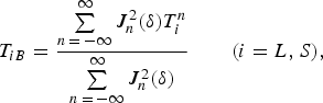 $${T_{iB}} = \displaystyle{{\sum\limits_{n \,=\, - \infty} ^\infty {J_n^2 ({\rm\delta} )T_i^n}} \over {\sum\limits_{n \,=\, - \infty} ^\infty {J_n^2 ({\rm\delta} )}}} \quad \quad (i = L,S), $$
where T in is the transmittance of the assembly at n-order side frequency spectral line. Obviously, with the increasing of the modulation parameter δ and/or νm, the transmittance of the laser decreases while that of the Stokes light increases passing through the assembly of wave plate and polarizer described above, that is to say, the ratio of the Stokes light filtered out from the laser is decreased. Consequently the suppression effect of the assembly of wave plate and polarizer on the SRRS will be decreased.
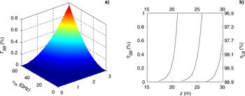
Introducing phase modulation into the narrowband laser pulse described in Section 4.1, the thickness of the wave plate is still 5.19 mm. Figure 4a shows the variation of the Stokes transmittance T SB through one assembly of wave plate and polarizer with the modulation parameters δ and νm. The transmittance T SB is still very small in the selected modulation parameters, just 0.36% when δ = 2.5 and νm = 49 GHz (the laser bandwidth Δλ = 0.1 nm). The broadband laser pulse (Δλ = 0.1 nm) transmission efficiency ηLB is still as high as near 99% if inserting three assemblies in the transmission paths of 30.0 m, and the peak transmission efficiency ηLB of the laser pulse can reach to 97.8% even if just two assemblies are used, as shown in Figure 4b.
(a) The variation of the Stokes transmittance T SB through one assembly with the modulation parameters δ and νm. (b) The variation of the broadband laser pulse (δ = 2.5, νm = 49 GHz, Δλ = 0.1 nm) transmission efficiency ηLB and the Stokes conversion efficiency ηSB at the incident plane of the wave plate with the location z of the assemblies.

5. SUMMARY
To increase the transmission efficiency of the high-energy and high-power laser pulses in long air paths, the method of suppressing SRRS by changing the polarization direction of the Stokes light is proposed, the scheme of the method is achieved using the assembly of wave plate and polarizer. For the narrowband laser pulse with central wavelength of 351 nm, intensity of 2 GW/cm2 and width of 3 ns, the optimum thickness of wave plate is calculated and equals 5.19 mm. The threshold distance of SRRS in air can be lengthened to 30.0 m from 16.2 m easily only using two assemblies. For the broadband laser pulse caused by phase modulation, the suppression effect of the assembly on the SRRS will be decreased to some degree; however, the threshold distance of SRRS can still reach to 30.0 m if using three assemblies. So the method is applicable for both narrowband and broadband lasers, of course, some effects will be induced, such as energy loss, wavefront distortion and so on, however the effects do much less harm to laser systems than SRRS, and are within acceptable limits. The method has the advantages of simple structure, stable performance, and convenient maintenance.
ACKNOWLEDGMENT
This project is supported by the National Natural Science Foundation of China (Grants No. 61378007 and 61138005).