1 Introduction
Hall thrusters have been widely applied for orbital transfer and attitude control of satellites due to advantages such as simple structure, high specific impulse, high efficiency and high reliability. The key life-limiting factors of conventional Hall thrusters, namely the high-energy electron and ion power deposition to the channel walls and ion-bombardment sputter erosion of the discharge channel, have been investigated extensively for a wide range of thruster scales. As thruster power is reduced to the ‘miniature’ (i.e. sub-500 W) power regime, the increased surface-to-volume ratio of the discharge channel and decreased thruster component sizes promote increased plasma–wall interactions and susceptibility to overheating, thereby reducing thruster operational lifetime and performance. An efficient, high specific impulse, high thrust-to-power ratio, long-life, low-power Hall thruster would be attractive for a wide range of space missions, such as deep space missions and near-Earth missions (Conversano et al.
Reference Conversano, Goebel, Hofer, Matlock and Wirz2015). Numerous miniature Hall thrusters have been developed in an effort to meet this need. For example, the 200 W class Hall thrusters, such as the SPT-30 (Jacobson & Jankovsky Reference Jacobson and Jankovsky1998), BHT-200 (Hruby et al.
Reference Hruby, Monheiser, Pote, Kolencik, Freeman and Rostler1999; Beal, Gallimore & Hargus Reference Beal, Gallimore and Hargus2002; Smirnov, Raitses & Fisch Reference Smirnov, Raitses and Fisch2002; Ito, Gascon & Crawford Reference Ito, Gascon, Crawford and Cappelli2006; Ito et al.
Reference Ito, Gascon, Crawford and Cappelli2007; Cheng & Martinez-Sanchez Reference Cheng and Martinez-Sanchez2008; Hargus & Charles Reference Hargus and Charles2008), MaSMi-40 thruster (Conversano et al.
Reference Conversano, Goebel, Hofer, Matlock and Wirz2013, Reference Conversano, Goebel, Mikellides, Hofer, Matlock and Wirz2014, Reference Conversano, Goebel, Hofer, Matlock and Wirz2015) and the wall-less Hall thruster (Mazouffre, Tsikata & Vaudolon Reference Mazouffre, Tsikata and Vaudolon2014a
; Vaudolon et al.
Reference Vaudolon, Mazouffre, Hénaux, Harribey and Rossi2015), have been designed and tested. The primary challenges of the SPT-30 and BHT-200 are the short lifetimes (600 h and 1500 h respectively) due to rapid erosion of, and high electron/ion-losses to, the discharge channel walls; these result from the inherently higher surface-to-volume ratio of small thrusters. A large effort has been made to study the influence of the magnetic field on discharge performance and thruster lifetime. The result in Hofer, Jankovsky & Gallimore (Reference Hofer, Jankovsky and Gallimore2006) shows the effect of magnetic field topography, or the effect of trim coil on discharge characteristics at high/low discharge voltage, but relevant contents of power deposition into walls are not involved. The findings of Garrigues et al. (Reference Garrigues, Hagelaar, Bareilles, Boniface and Boeuf2003) reveal that a zero magnetic field zone configuration near the anode contributes to a decrease of the eroded zone length and erosion intensity. However, the magnetic field topology varies in different cases. The effect of magnetic field profile on the anode fall in a Hall effect thruster discharge can be found in Dorf, Raitses & Fisch (Reference Dorf, Raitses and Fisch2006), including the influence of plasma potential, electron temperature and plasma density near the anode zone on negative and positive anode changes, whereas it does not involve discharge performance or power deposition into BN (boron nitride) walls. Garrigues et al. (Reference Garrigues, Mazouffre, Hénaux, Vilamot, Rossi, Harribey, Bourgeois, Vaudolon and Zurbach2013) put forward a new flexible magnetic circuit which can form multiple kinds of magnetic field configurations, keep the maximum magnetic field intensity at the channel outlet and change the magnetic field gradient in the channel (without a reverse negative gradient magnetic field), but test data keeping the maximum magnetic field intensity at the channel outlet and changing the magnetic field gradient in the channel are unavailable. In order to improve the lifetime of a lower-power thruster, the MaSMi-40 thruster with magnetic shielding (MS) has been designed to decrease plasma–surface interaction, which reduces the ion flux at the walls and leads to a longer lifetime and lower ion loss to the discharge walls. However, MS needs more input power to the magnetic coils, and the electron loss to the discharge walls is large, which would decrease the reliability of the whole system (Conversano et al.
Reference Conversano, Goebel, Hofer, Matlock and Wirz2013, Reference Conversano, Goebel, Hofer, Matlock and Wirz2015). An X-shaped radiator with a total space-viewing surface area of
 ${\sim}1000~\text{cm}^{2}$
is adopted for the thruster shell to guarantee the long-time stable work of the thruster (Conversano et al.
Reference Conversano, Goebel, Hofer, Matlock and Wirz2013). The MS technology is also used in the newly 200 W wall-less thruster. The channel erosion rate is significantly reduced by moving the anode to the exit plane of the discharge channel, shifting the region where ionization and acceleration take place entirely outside of the channel. However, in this design, a large fraction of hot electrons originating from the external cathode are trapped along the magnetic field lines and directly lost at the anode. The discharge current is therefore high while the efficiency is low (Mazouffre, Tsikata & Vaudolon Reference Mazouffre, Tsikata and Vaudolon2014b
). Although a permanent magnet is adopted for the 200 W wall-less thruster researched and manufactured at the Centre National de la Recherche Scientifique, a central-copper heat drain is employed to evacuate heat towards a radiator placed behind the thruster, maintaining the long-time discharge of the thruster.
According to the existing research status of low-power MS and wall-less thrusters, to realize MS technology and meet the requirements for long-service life, high thermal loads on the thruster seem to be unavoidable due to power deposition on the walls caused by coil heat and the plasma, and a heat pipe or radiator needs to be adopted for heat dissipation. To solve this problem, we put forth a new kind of technology to push down the excited magnetic field with two permanent magnetic rings as in Ding et al. (Reference Ding, Peng, Wei, Sun, Li and Yu2016), which can lead to low electron/ion losses at the walls. It is well known that power deposition on the walls depends on the ionization position and space potential; magnetic field configuration, intensity and gradient are the important factors affecting ionization position and potential in the channel. Generally, coil magnetization is adopted for traditional Hall thrusters; the magnetic field gradient on the medium diameter line is approximately 10–
 $15~\text{Gs}~\text{mm}^{-1}$
; a 20–
 $30~\text{Gs}~\text{mm}^{-1}$
magnetic field gradient can be produced on the medium diameter line in the channel by adopting excitation by two magnetic rings. Such intense magnetic field gradients will reduce the length of the ionization region, which will further affect power deposition of electrons and ions on the walls. Since the magnetic field produced by a permanent magnet is inconvenient for adjustment, relevant research is developed in this paper based on a 200 W Hall thruster model with three magnet exciting coils and a focusing magnetic field configuration. A magnetic field with different gradients is formed by changing the ampere-turns of three magnet exciting coils. Under the precondition that the magnetic intensity at channel exit is unchanged and the magnetic field configuration in the channel is unchanged, the effect of the magnetic field gradient on the discharge characteristic in the channel and power deposition on the walls is further studied.
The general organization of this paper is as follows: § 2 – magnetic field characteristics, § 3 – general disruption of the PIC Model, § 4 – results and discussion and § 5 – conclusions.
2 Magnetic field characteristics
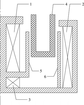
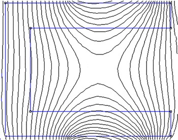
To guarantee that the magnetic intensity at the channel exit and magnetic field configuration in the channel are unchanged, only the effect of the magnetic field gradient on power deposition on the walls is studied. We adopt an ATON-type magnetic structure (i.e. three magnet exciting coils: inner coil, outer coil and trim coil) to adjust the magnetic field; see figure 1 for the magnetic structure, and see figure 2 for the produced magnetic field configuration. It has a typical ‘zero magnetic field’ characteristic, and it creates the same magnetic field configuration as if it was produced through excitation of two permanent magnetic rings.
Magnetic structure with 1 – inner coil; 2 – outer coil; 3 – trim coil; 4 – discharge channel; 5 – inner magnetic screen; 6 – outer magnetic screen.

Magnetic field configuration.

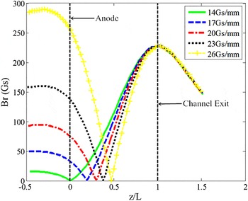
Under the precondition that the magnetic intensity at the channel exit and the magnetic field configuration in the channel are unchanged, through adjustment of the ampere-turns of the inner coil, outer coil and trim coil, the obtained magnetic field gradient is 14, 17, 20, 23 and
 $26~\text{Gs}~\text{mm}^{-1}$
for Case 1, Case 2, Case 3, Case 4 and Case 5 respectively, as shown in figure 3. The anode position is at horizontal coordinate 0. As the continual increase of the magnetic field gradient and the magnetic field gradient approach zero at the channel exit, the channel length and anode position are kept unchanged.
Magnetic field gradient distribution. (Br is the magnetic field strength along the radial direction.)

3 General description of the particle in cell model
The 2D-3V particle-in-cell (PIC) and Monte Carlo collisions (MCC) model we developed employs the particle in cell method combined with the Monte Carlo method to simulate the neutral gas, electrons and ions, including their positions, speeds and energies. This model has been used to study double-stage Hall thrusters, magnetic mirror effects and electron near-wall transport (Hofer et al. Reference Hofer, Jankovsky and Gallimore2006; Yu et al. Reference Yu, Li, Wu, Ning and Yan2009, Reference Yu, Song, Li, Liu and Han2012a ,Reference Yu, Song, Liu, Ding and Li b ; Li et al. Reference Li, Zhang, Liu and Yu2010; Li, Ning & Yu Reference Li, Ning and Yu2013; Liu et al. Reference Liu, Wu, Yu, Cao and Duan2010, Reference Liu, Chen, Zhao and Yu2015).
The model is fully consistent, and the wall sheaths, wall energy conservation and anomalous transport (Bohm diffusion) are all considered. The initial speed of the new particles is treated according to the half-Maxwell distribution and the Poisson equation is solved by the dynamic alternating direct implicit method. The anomalous collisions, electron–wall collisions and electron–neutral collisions are simulated by the Monte Carlo method. The Bohm collision frequency is defined as
 $V_{B}=\unicode[STIX]{x1D705}_{B}\unicode[STIX]{x1D714}_{ce}/16$
, where the coefficient
 $\unicode[STIX]{x1D705}_{B}$
is set as
 $1/4$
and
 $1/16$
in the plume region and discharge channel, respectively, and
 $\unicode[STIX]{x1D714}_{ce}$
is the electron gyro-frequency.
In order to reduce the computation time, the mass of the heavy particles is increased by a factor of
 $1/f$
so that the velocity of the ions increases by
 $\sqrt{f}$
to reduce the time scale by the same amount, and the collision cross-section has to be increased
 $\sqrt{f}$
times to preserve the density of plasma in the discharge channel. According to the requirement for the Hall parameter, we set
 $\sqrt{f}$
to 0.04. Furthermore, the vacuum permittivity constant is increased by a factor
 $\unicode[STIX]{x1D6FE}^{2}$
to reduce the number of grids and iterations. In order to consider the degree of charge unbalance, we set
 $\unicode[STIX]{x1D6FE}^{2}$
as 144. Additionally, this model makes a number of assumptions, including a constant neutral axial velocity, quasi-neutral cathode boundary, half-Maxwellian distribution of initial particles and it ignores the collisions of atoms with other atoms and ions as well as the existence of double charged ions. The electrons are ejected from the exhaust plane into the channel by the quasi-neutral injection method to assure convergence. This 2D-3V PIC-MCC model is applied to study the effects of the magnetic field gradient on plasma discharge and wall losses.
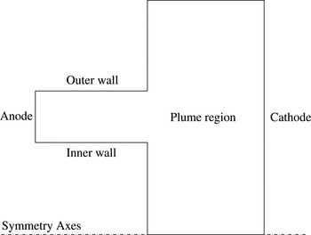
Model of a Hall thruster.

The model for a Hall thruster used in this article is shown in figure 4. In the discharge channel, the left lateral boundary is the anode while the lower and upper boundaries are both dielectric walls. During the computing process, the location of the anode and the channel length are kept constant. At the same time, a plume region of the thruster is considered in the model. In the plume region, the right lateral boundary is the cathode. The relative positions of the anode, cathode and magnetic field remain unchanged. A secondary electron emission model is considered at the dielectric walls. The mass flow
 $\text{ratem}_{a}=1~\text{mg}~\text{s}^{-1}$
and discharge voltage
 $U_{d}=250~\text{V}$
are applied at the anode and 0 V is applied at the cathode.
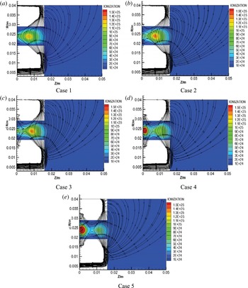
Ionization rate distribution. (R: the distance in the radial direction; Z: the distance in the axial direction.)

4 Results and discussion
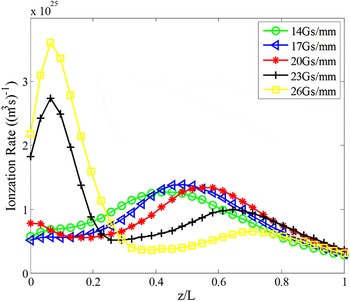
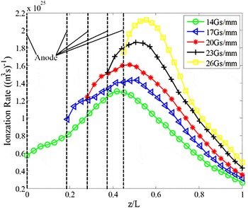
Ionization of neutral gas in the channel is one of the most important physical processes of Hall thrusters, and the position of the ionization region and ionization rate will directly affect the performance of the thruster. The position of the ionization region in the discharge channel and the axial ionization rate distribution along the channel median line are shown in figures 5 and 6, respectively.
Axial ionization rate distribution along the channel median line.

According to figures 5 and 6, due to the increase of the axial magnetic field gradient and the shift in location of the zero magnetic field position, the axial position of ionization region gradually moves to the channel exit, meanwhile, the ionization region is compressed. For Case 1 and Case 2, the increase of the magnetic field gradient makes the ionization region move to the channel exit and the ionization rate also increases. For Case 3, Case 4 and Case 5, although the ionization region also moves to the channel exit, the large reversing magnetic intensity between anode and zero magnetic field position cause enhanced ionization near the anode, and thereby a second ionization region is created. Especially for Case 4 and Case 5, the ionization rate near the anode region exceeds that of the primary ionization region and now becomes the main ionization region.
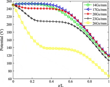
Due to the existence of the magnetic field in the channel, the electrons produced by ionization of neutral gas are restrained by the magnetic field in their movement to the anode; this affects the distribution of conductivity in the channel, further affecting the potential distribution in the channel. See figure 7 for the axial potential distribution along the channel median line. According to figure 7, for Case 1 and Case 2, the potential drops between the zero magnetic field position and channel exit. With the increase of the magnetic field gradient, the starting point of the drop in the potential and the ionization region are axially shifted together. Compared with the working condition that the magnetic field gradient is small and there is no second ionization region, for Case 3–Case 5, the magnetic intensity at the position near the anode region is high, which restricts the movement of electrons through the magnetic field; two potential drop intervals form the two ionization regions; particularly for Case 4 and Case 5, a big potential drop forms near anode region.
Axial potential distribution along the median line.

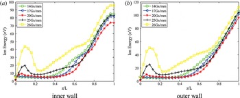
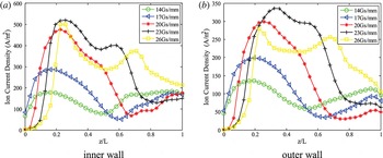
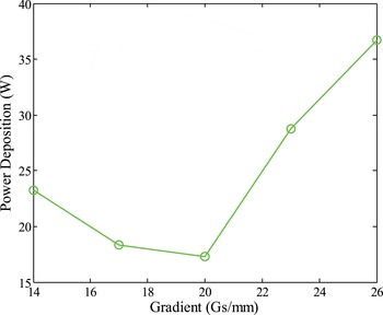
As shown in figure 7, since the second ionization region forms near the anode region, a big potential drop also forms near the anode region. High energy is obtained by the ions produced by ionization in the second ionization region during the process of moving out of the channel; the energy of the ions bombarded into the walls also increases, as shown in figure 8. Meanwhile, the ions generated from the second ionization region also make the current density of ions bombarded into the walls increase; see figure 9. The increase in energy and density of ions bombarded into the walls will accelerate the power deposition of ions at the wall position. The existence of the second ionization region also accelerates the power deposition of electrons at the wall position, which results in an increase of overall power deposition, as shown in figure 10.
Axial ion energy distribution in the walls.

Axial ion current density distribution in the walls.

Power deposition into the walls.

According to figure 10, when the magnetic field gradient is
 $14~\text{Gs}~\text{mm}^{-1}$
, the power deposition on the walls is approximately 23 W. With the increase of magnetic field gradient, the power deposition on the walls starts to decrease. This is because the increase of the magnetic field gradient results in the movement of the ionization region; the location where the ions are produced by ionization is closer to the channel exit; the current density and energy of ions bombarding the walls decreases, which reduces the energy deposition of ions at the walls. The result is consistent with that in Garrigues et al. (Reference Garrigues, Hagelaar, Bareilles, Boniface and Boeuf2003) where the performance and lifetime of a Hall thruster with various magnetic field configurations were investigated and it was found that a configuration with a zero magnetic field zone near the anode (the magnetic field gradient is greater correspondingly) leads to decrease of the length of the eroded zone and the intensity of the erosion. However, when the magnetic field gradient reaches
 $20~\text{Gs}~\text{mm}^{-1}$
, with the continued increase of the magnetic field gradient, the ions produced by ionization in the second ionization region are accelerated by the electric field during the process of moving out of the channel and the obtained energy is high, therefore the energy of the ions bombarding the walls is high. Meanwhile, the ions produced by the second ionization region will also make the current density of ions bombarding the walls increase, accelerating the power deposition of ions on the walls. The existence of the second ionization region also enhances the power deposition of electrons on the walls, which results in the quick increase of total power deposition on the walls.
To avoid the effect of the high magnetic field near the anode region and to avoid the power deposition of electrons and ions produced by the second ionization region on the walls, we performed a further improvement: during the continued increase of the magnetic field gradient, the axial position of the anode is always moved to the zero magnetic field position. That is to say, it can be guaranteed that the magnetic intensity at the anode position is the lowest, and the relevant PIC calculation is performed under such a condition.
Axial ionization rate distribution along the median line.

Axial potential distribution along the median line.

See figures 11 and 12 for the axial ionization rate distribution and potential distribution along the median line when the anode is always at the zero magnetic field position. According to figure 11, by increasing the magnetic field gradient, the ionization region movement and compression effect are more obvious. Furthermore, the ionization rate also increases; the maximum value increases from
 $1.27\times 10^{25}$
to
 $2.10\times 10^{25}~(\text{m}^{3}~\text{s})^{-1}$
when the magnetic field gradient is increased from 14 to
 $26~\text{Gs}~\text{mm}^{-1}$
. In figure 13, during the process whereby the magnetic field gradient increases from 14 to
 $26~\text{Gs}~\text{mm}^{-1}$
, the axial potential distribution lines along the median line are almost the same and the potential decreases from 250 V at the anode position to approximately 112 V at exit the position.
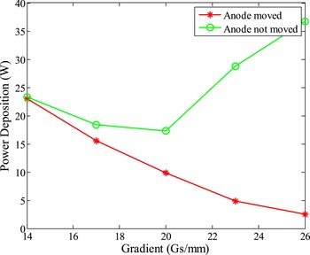
See figure 13 for a comparison of the power deposition on the walls between the situation where the anode moves along with the zero magnetic field position and the situation where the anode does not move. Obviously, during the process that the magnetic field gradient gradually increases, the anode is placed at the zero magnetic field position; this avoids the creation of a second ionization region, which largely reduces the bombardment of high-energy ions and electrons on the walls of the discharge channel. Power deposition only occurs on the walls near the channel exit, and the total power deposition is reduced by approximately 90 %.
Power deposition into the walls.

5 Conclusions
The effect of the magnetic field gradient on the wall power deposition of Hall thrusters is studied in this paper based on the 2D-3V PIC-MCC model. The simulation results and analysis show that as the magnetic field gradient increases, a second ionization region will form in the anode region and ions and electrons produced in this second ionization region will be accelerated and therefore increase the power deposition on the walls, if the position of anode is kept unchanged in high magnetic fields. On the contrary, if the position of the anode is maintained at the zero magnetic field position, the ionization region will move to the channel exit when the magnetic field gradient is increased; the ionization rate will increase and the ionization region will be condensed, which largely reduce the power deposition of electrons and ions on the walls and effectively reduce the thermal load of the thruster. These results also indicated that the matching of the magnetic field gradient and the length of the discharge region is an important control parameter for the ionization and power deposition of Hall thrusters. Related experimental verification is in progress.
Acknowledgements
The authors want to gratefully acknowledge the financial support from the National Natural Science Foundation of China (grant nos 51477035 and 51507040).