Introduction
The unceasing evolution of electromagnetic sensors has created a tremendous impact on wireless communication, especially in the development of Wearables and Wireless Body Area Networks (WBANs) for long-term usage as it does not have the inherent risk of ionizing radiation on the user [Reference Soni, Yadav and Kumar1]. Wearables and WBAN sensors play an inevitable role in medical healthcare because of their capability to offer non-intrusive stimulations and real-time data transfer. This feature has employed these sensors for various biomedical applications [Reference Singh, Bangari, Ali, Vyas, Verma and Saxena2]. Apart from medical applications, these systems are used for the design of intelligent devices for child-care and elder care, measuring physical activities for physiotherapy and sportsmen [Reference Shirvani, Khajeh-Khalili and Neshati3, Reference Singh, Gehlot, Khilrani, Mittal, Nilanjan, Amira S., Simon James and Chintan4], tracking and positioning systems for rescue operations, and military applications [Reference Baudh, Sahu, Parihar and Kumar5]. The most fundamental component of the systems/sensors is the antenna.
One of the many challenges in developing a WBAN antenna is the miniaturization to make it unobtrusive. Several miniaturization techniques were followed in the previous works such as symmetric field distribution and cutting technique [Reference Zhu, Guo and Wu6], 3-D corrugated ground structure [Reference Samal, Chen and Fumeaux7], Characteristic Modal Analysis (CMA) [Reference Elias, Soh, Al-Hadi and Vandenbosch8, Reference Bhattacharyya, Pal, Patra and Gupta9], etc. The designed antenna must satisfy important constraints such as high gain [Reference Trajkovikj and Skrivervik10–Reference Gao, Tian, Shou and Li15], low SAR, and bending resilience, and should have frequency stability while placed over the user’s body [Reference Li, Jiang and Zhao16]. The designed antenna is expected to produce electric fields at a very low level to whittle down the SAR below the Federal Communication Commission (FCC) SAR limit of 1.6 W/Kg for 1 g of human tissue or the Council of European Union’s limit of 2 W/Kg for 10 g of human tissue [Reference Fernandez, Espinosa, Guerra, Pena, Thiel and Arrinda17]. A rigid substrate for the antenna and a flexible substrate for the ground to reduce the effects of SAR are explained in [Reference Singh and Verma18]. The effects of the ground plane of the antenna and its impact on the SAR are studied in [Reference Le and Yun19, Reference Hussin, Ezzaty, Soh, Jamlos, Lago and Al‐Hadi20]. For a wearable antenna various method to keep SAR within the range is presented. The antenna is fabricated on a low-loss rigid substrate while a conductive textile is used as a ground plane to avoid the incident wave interaction with the human body [Reference Zhang, Cheng, Luo and Chen21]. Literature shows the study about the usage of metamaterials for WBAN antenna to reduce the SAR well below the standards by altering the permeability and the permittivity of the substrate artificially [Reference Shariff, Ali, Mane, Alsath, Kumar, Pathan, Kishk and Khan22–Reference Ali, Ullah and Matekovits27]. Meta-surfaces such as Electromagnetic Band-Gap structures (EBG) are utilized for the SAR reduction and performance enhancement by reducing the back radiation and the impact of the detuning effect [Reference Tak and Choi28–Reference Velan, Sundarsingh, Kanagasabai, Sarma, Raviteja, Sivasamy and Pakkathillam32]. Defected Ground Structure (DGS) [Reference Shirvani, Khajeh-Khalili and Neshati3, Reference Zaidi, Abd Rahman, Yahya, Nordin, Subahir, Yamada and Majumdar33, Reference Sran and Sivia34], and EBG along with (DGS) [Reference Ashyap, Dahlan, Abidin, Dahri, Majid, Kamarudin, Yee, Jamaluddin, Alomainy and Abbasi35] and Artificial Magnetic Conductor (AMC) [Reference Nadh, Madhav, Siva Kumar, Anilkumar, Venkateswara Rao and Kishore36–Reference Paracha, Rahim, Soh, Kamarudin, Tan, Lo and Islam40] were reported in the literature.
This work shows how Characteristic Mode Analysis (CMA) is employed to optimize the electromagnetic response of a low-profile wearable antenna. This makes sure the antenna complies with the design constraints. The CMA is leveraged by the identification of the dominant modes of the antenna and the suppression of the unwanted modes geometrically. This leads to optimized radiation characteristics. The compact antenna has a footprint area of 3.5 × 3.25 cm2. Mode elimination lowers Specific Absorption Rate (SAR), but due to the partial ground of the monopole, back radiation results in marginal SAR reduction at 0.5 W input power.
To further enhance wearable antenna performance, this work introduces an AMC engineered for dual-band operation at 2.45 and 5.9 GHz. The AMC array consists of a dual concentric ring, functions as a metasurface to produce in-phase reflection at the desired 2.45 and 5.9 GHz. This also enhances the peak gain, bandwidth of the antenna, and reduces body effects by providing isolation between human body and antenna. The constructive interference mitigates the back radiation and keeping the SAR value at check. Integrating the mode-controlled antenna design with the engineered AMC, this work bridges the gap between mode optimization of antenna structures and magnetically reflective surface, offering a novel approach for safe and efficient wearable bio-telemetry systems.
This structure of the paper is laid out as follows. Section II discusses the CMA based on the linear combination of the eigenmodes. Section III discusses the characterization of the novel proposed antenna. Section IV discusses the design of the AMC and its inherent characters are analyzed. Section V discusses the characterization of the antenna mounted over the AMC layer in free-space. Section VI discusses the over-the-body behavior of the antenna and antenna + AMC. Sections VII and VIII discuss the SAR analysis and the effect of antenna under bent condition, respectively.
Characteristic eigen mode theory
This section provides a basic insight of the CMA based on the eigenmodes. It discusses the crucial role in the design of an antenna for the desired frequencies by extracting the fundamental modes and far-field behavior for an arbitrary structure (Perfect Electric Conductor) independent of the source. Harington and Mautz developed the CMA theory for antenna by considering the linear relationship between the surface current density and the tangential component of the incident electric field. The theory of characteristic modes is conceptually similar to that of the Fourier series. Any arbitrary periodic wave form can be written as a linear combination of the fundamental frequency and its harmonics weighted by suitable coefficients. The same concept can be used in electromagnetics as Maxwell’s equation is linear, the electric field can be written as the linear combination of their eigenmodes. The energy contained in the electromagnetic wave is bounded, this phenomenon enables Maxwell’s equation to form orthogonal basis functions and possible linear combinations of the physical quantity and also could find the coefficients of the harmonics. When no source is given, the computed current modes of the arbitrary antenna structure called is the characteristic modes or characteristic currents governs the resonance, gain, bandwidth and polarization which depends only on the size and shape of the design.
Mathematical formulations of the CMT
Based on the insights from [Reference Cabedo-Fabres, Antonino-Daviu, Valero-Nogueira and Ferrando Bataller41], the weighted eigenvalue  ${\lambda _n}$ of the eigenfunctions is used to obtain the characteristic currents
 $\overrightarrow {{J_n}} $ of the patch by relating the real and the imaginary parts of the impedance Z = R + jX
 \begin{equation}\,X\left( {\overrightarrow {{J_n}} } \right) = \,{\lambda _n}R\,\left( {\overrightarrow {{J_n}} } \right)\end{equation}
From reciprocity theorem, the impedance operator Z has symmetricity and linearity, and hence the Hermitian parts R and X will also be linear and symmetrical. Therefore eigenvalue  ${\lambda _n}$ given by equation (1) is all real and the eigenfunctions
 $\overrightarrow {{J_n}} $ over the defined surface is chosen to be a scalar value or equiphasal (a real function scaled by a complex constant). The orthogonality of the characteristic modes depends upon the R of the is a Z operator in (1), which is stated in terms of Kronecker delta function
 ${\delta _{mn}}$ as,
 \begin{equation}\left[ {\vec J_m^*,R{{\vec J}_n}} \right] = \,{\delta _{mn}}\end{equation}
 \begin{equation}\left[ {\vec J_m^*,X{{\vec J}_n}} \right] = \lambda_n {\delta _{mn}}\end{equation}
Depending in the size and the shape of the radiating patch, the surface current  $\overrightarrow {{J_n}} $ define the characteristic modes. Equation (1) in the matrix form is,
 \begin{equation}\left[ X \right]\,\overrightarrow {{J_n}} \, = \,{\lambda _n}\,\left[ R \right]\,\overrightarrow {{J_n}} \,\end{equation}
The eigenvalues ( ${\lambda _n})$ and the eigenvectors (
 $\overrightarrow {{J_n}} )\,$can be obtained by solving equation (4). The eigenvectors are calculated for the free space. The characteristic electric fields (
 $\overrightarrow {{E_n}} )$ on the surface of the conducting body are produced by the characteristic currents (
 $\overrightarrow {{J_n}} )$.
 \begin{align}
{E_n}\left( {\overrightarrow {{J_n}} } \right) &= Z{\text{ }}(\overrightarrow {{J_n}} ) \nonumber\\
&=R \left( {\overrightarrow {{J_n}} } \right)\,\, + jX(\overrightarrow {{J_n}} ) \nonumber\\
{E_n}\left( {\overrightarrow {{J_n}} } \right)& = R\left( {\overrightarrow {{J_n}} } \right)\,\,\left( {1 + j{\lambda _n}} \right)\end{align}
The characteristic fields are R ( $\overrightarrow {{J_n}} )$ multiplied by a complex term
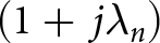 $\left( {1 + \,j{\lambda _n}} \right)$ making it equiphasal. The orthogonality of these fields can be established by the complex Poynting theorem.
 \begin{equation*}P\,({J_m},{J_n}) = \left[ {\overrightarrow {J_m^*} ,Z\overrightarrow {{J_n}} } \right] = \left[ {\overrightarrow {J_m^*} ,R\overrightarrow {{J_n}} } \right] + \left[ {\overrightarrow {J_m^*} ,X\overrightarrow {{J_n}} } \right]\end{equation*}
 \begin{equation*} = \mathop{{\int\!\!\!\!\!\int}\mkern-21mu \bigcirc}
{\left( {\overrightarrow {{E_m}} x\,\vec H_n{^*}} \right)} \,ds\, + \,j\omega \,\mathop {\iiint {\left( {\mu {{\vec H}_m} \bullet \vec H_n{^*}\, - \,\varepsilon {{\vec E}_m}\, \bullet \vec E_n{^*}} \right)}}\,d\tau \,\end{equation*}
 \begin{equation} = \,\,\left( {1 + \,j{\lambda _n}} \right)\,{\delta _{mn}}\end{equation}
This orthogonality is observed on the surface of the radiating patch and at the infinity sphere enclosing the patch. These modes transmit power without depending on other modes forming the basis set. The total current on the surface is given as J,
 \begin{equation}J\, = {\sum _n}\frac{{V_n^i\,{J_n}}}{{1 + j{\lambda _n}}}\end{equation}
 \begin{equation}V_n^i\, = \,\left[ {{J_{n,}}{{\textrm E}^i}} \right] = \oint {{J_n}} \bullet \,{{\textrm E}^i}ds\end{equation}
The product  $V_n^i\,{J_n}$ denotes the coupling between the corresponding mode and the excitation and
 $V_n^i$ is the modal excitation coefficient. At resonance
 ${X_L} = {X_C}$, hence X = 0, from equation (1), |
 ${\lambda _n}$| = 0. When
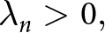 ${\lambda _n} \gt 0,$ the mode stores magnetic energy and when
 ${\lambda _n}$< 0, the mode stores electric energy. From equation (7), the eigenvalues and the modal expansion of the current is inversely proportional, it is more consistent to analyze a term called Modal Significance (MS), given by equation (9), as it gives the normalized amplitude of the modes of the current depending on the shape and the size of the structure.
 \begin{equation}MS\, = \,\left[ {\frac{1}{{1 + \,j{\lambda _n}\,}}} \right]\end{equation}
Another representation of the eigenvalues is the Characteristic angles defined by equation (10) giving an insight about the phase difference between the Modal currents,  $\overrightarrow {{J_n}} $ and the corresponding electric field
 ${E_n}$.
 \begin{equation}{\alpha _n}\, = \,180^\circ \, - \,ta{n^{ - 1}}\left( {{\lambda _n}} \right)\end{equation}
Resonance occurs when  $\lambda_n = 0, \alpha_n=180^\circ$.
Modal analysis of the structure of the antenna
The Characteristic modes of the dual L shaped antenna were analyzed to obtain a dominant mode at 5.9 GHz. The structure of the antenna was obtained through the following stages shown in Figure 1. Initially, the analysis of the design starts from a simple square patch of size 32.5 × 35  $m{m^2}$ had evolved to a novel structure. The modal significance and the characteristic angle graph of the stages A, B, C is given in Figure 1.
Modal significance and characteristic angle and S parameters of stages A, B, and C.

Modal analysis of the patch at stage A, modes 2 and 3 are dominant produce resonance at 5.49 and 4.76 GHz, respectively. However, no resonance at the desired frequency. The modal study of the stage B, modes 2 and 4 dominates resonating at 7.54 and 3.84 GHz. Analyzing the characteristic modes of the patch in stage C, mode 3 is a dominant mode producing a resonance at 5.9 GHz. Suitably exciting the dominant modes produces resonance at 5.9 and 2.45 GHz. The corresponding return loss characteristics show the resonance at the dominant modes at each stage.
Design of the antenna
After the CMA, the proposed design is optimized over the Rogers 4534 substrate ( ${\varepsilon _r}$=3.5 and tan δ = 0.0022). The thickness of the substrate is 1.524 mm. Figure 2 prototypes the structure of the presented antenna. The electrical dimension of the antenna is 0.286
 $\,{{{\lambda }}_0}$ x 0.265
 $\,{{{\lambda }}_0}$ x 0.012
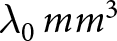 ${ }{{{\lambda }}_0}\,m{m^3}$, where
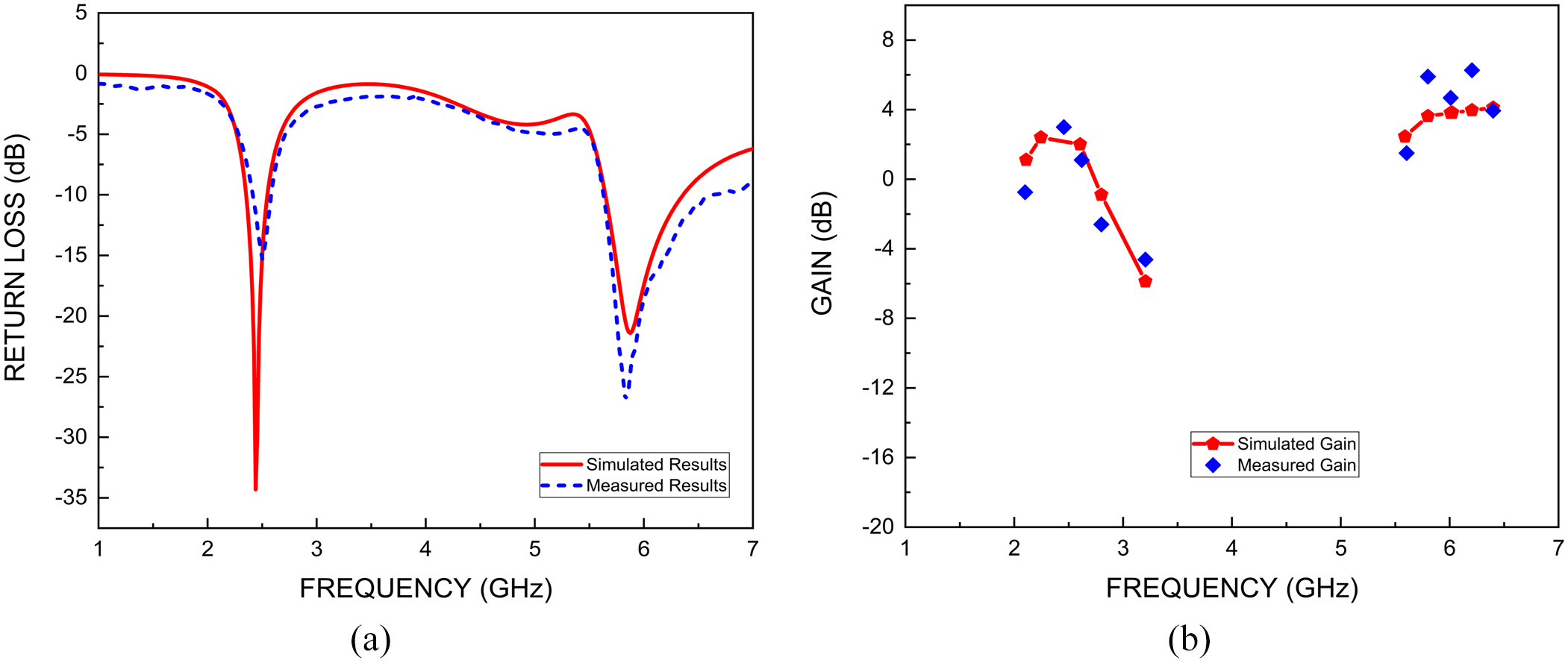
 ${{{\lambda }}_0}$ is the free space wavelength at 2.45 GHz. The antenna excites the fundamental mode at 2.45 GHz and the higher-order mode at 5.9 GHz. Table 1 provides the summary of Figure 3 showing the return loss of −37 dB, 190 MHz bandwidth and 3.49 dB gain for 2.45 GHz and −21.4 dB return loss, 720 MHz bandwidth and 3.2 dB gain in simulation and nearly similar measured results.
The prototyped antenna and dimensions.

Simulated and measured (a) return loss plot of the antenna and (b) gain plot of the antenna.

Summary and interpretation of Figure 3

Radiation mechanism of the antenna
More the surface current density at the specific sites of the radiating patch at resonance leads to concentrating the energy. This concentrated energy can enhance the antenna’s coupling ability with the electromagnetic field and hence more efficiently radiate or receive the energy. Observing Figure 4 explains the surface current density of the proposed antenna when the dominant mode 3 is excited. It has higher current density at the resonating length of the structure. Figure 5(a) and (b) shows radiation pattern of the antenna at 2.45 and 5.9 GHz. On observing, this kind of radiation pattern is not suitable for WBAN application as the radiation pattern has a shape of “8.” The lower lobe of the radiation pattern gets absorbed by the user’s tissue. This back-lobe must be mitigated.
Current distribution of the dominant eigen mode 3 of the proposed antenna.

Antenna’s radiation pattern at (a) 2.45 GHz and (b) 5.9 GHz.

Equivalent circuit model of the dominant modes of the antenna structure
The equivalent circuit model of the designed antenna which resonates at dual band is presented. The proposed equivalent circuit model is shown in Figure 6(a) and its response is shown in Figure 6(b). The resistor $\,{R_1}$and
 ${C_0}$ are for impedance matching purpose. The inductor
 ${L_1}$ and the capacitor
 ${C_1}$ in parallel is responsible for the resonance at the lower band. The inductor
 ${L_2}$ and the capacitors
 ${C_{21}}$ and
 ${C_{22}}$ in parallel is responsible for the resonance at the upper band. The impedance Z = R + jX, where R is the resistance and X is the reactance. Z can be determined for 2.45 GHz (
 ${f_1})$ and 5.9 GHz (
 ${f_2})$ from the Smith chart. Depending on the Z value, either L or C can be calculated for individual frequency bands.
 \begin{equation}{X_L}\, = \,\omega L\,\,{\text{and}}\,{X_C} = 1/\omega C\end{equation}
Determining one of the unknown for the required frequency, the other value can be calculated.
 \begin{equation}{f_1} = \frac {1} {2\pi \sqrt {{L_1}{C_1}} }\end{equation}
 \begin{equation}{f_2} = \frac{1}{{2\pi \sqrt {{L_2}({C_{21}} + {C_{22}})} }}\end{equation}
(a) Equivalent circuit of the proposed antenna 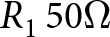 ${R_1}\,50{{\Omega }}$,
 ${C_0},\,{C_1}$ = 1.8 pF,
 ${L_1}$=1 nH,
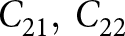 ${C_{21}},\,{C_{22}}$=0.6 pF,
 ${L_2}$ = 0.4 nH. (b) S parameters of the antenna’s equivalent circuit.

Design of the artificial magnetic conductor
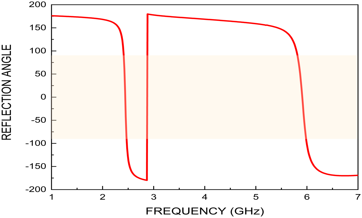
The proposed antenna is efficient, but still more electric field gets absorbed by the human tissues. In order to satisfy the criteria for Wearable Body Area Network, an AMC was incorporated along, backing the antenna. The AMC plays the role of a reflecting surface for the antenna, due to its behavior as a perfect magnetic conductor (PMC) at the desired frequency which is characterized by a zero-degree reflection phase, with a reflection phase bandwidth of range ± 90°. A unit cell of AMC having two concentric square rings as shown in Figure 7(a), is excited with TE10 mode to produced 0° phase angle of the reflection at 2.45 and 5.9 GHz hence acting a PMC. The in-phase reflection interferes constructively with the incident wave and hence enhancing the performance of the antenna.
(a) Unit-cell with dimension. (b) AMC array. (c) Current distribution when EM wave incidents.

At the reflection phase range of −90° to −180° and + 90° to + 180°, the unit cell behaves as a conductor. The single unit cell is designed to an array of 3 × 3 elements to make it act as an AMC. The AMC is designed on Rogers 4534 substrate ( ${\varepsilon _r}$=3.5 and tan δ = 0.0022) of thickness 1.524 mm. The length of each concentric square ring was calculated in accordance with the following equations.
 \begin{equation}\Theta = \beta l\,\quad or\quad \,l = \Theta / \times \beta \end{equation}
Where β (= ${k_o},{\text{ wave number}}$) is the phase constant and l is the physical length and Θ is the reflection phase
 \begin{equation}l\, = \,\frac{{\phi \,( {{\frac{\pi }{{180}}}} )}}{{\sqrt {{\varepsilon_{eff}}} {k_0}}}\;{\text{where}},\,\;{k_o} = {\frac{{2\pi f}} {c}}\end{equation}
The unit-cell is extended as a 3 × 3 array to behave as an AMC layer as shown in Figure 7(b). Figure 7(c) shows the current density at the surface of the ring structures showing the outer rings of the AMC array having higher current density is responsible for 0° reflection at 2.45 GHz and in other case, the inner rings of the AMC array having higher current density is responsible for 0° reflection at 5.9 GHz. Figure 8 shows the zero-degree reflection phase at 2.45 and 5.9 GHz produced.
Reflection phase of the AMC array.

The AMC reflector behaves like a mirror for the EM waves at the design frequencies, thus, altering the field distribution in the antenna vicinity. The interference of the EM waves between the antenna and AMC is constructive and modifies the surface current distribution of the antenna.
Design of the artificial magnetic conductor
The proposed antenna is placed over the AMC layer. A thin layer of styrofoam is placed in between the antenna and the AMC layer to serve the purpose of isolation. The thickness of the foam layer is about 4–5 mm. The overall dimensions of the antenna are 0.613 ${{{\lambda }}_0}$ x0.613
 ${{{\lambda }}_0}$ x0.049
 ${{{\lambda }}_0}$
 $m{m^3}$. Figure 9 shows the antenna incorporated with the AMC layer and the cross-sectional assembly of the AMC backed antenna.
Top-view and side view of the antenna + AMC.

Figure 10(a) and (b) shows the return loss and gain of the antenna along with the AMC. The antenna has a return loss of −21.9 dB, a bandwidth of 230 MHz and a gain of 6.18 dB at 2.45 GHz. Also, a return loss of −36 dB, a bandwidth of 770 MHz and a gain of 10.02 dB at 5.9 GHz and is tabulated in Table 2. The effects of number of unit cells impact the performance of the antenna is tabulated in Table 3. The 3 × 3 is chosen based on optimized performance and size of the magnetic in phase reflector.
Simulated and measured (a) return loss plot of the antenna and (b) gain plot of the antenna with AMC.

Summary and interpretation of Figure 10

Effect of number of unit-cell of AMC on the antenna performance

Radiation mechanism of the antenna with AMC
Figure 11 shows the surface current distribution of the antenna and AMC while placed together while at (a) lower and (b) upper band. On comparing the current distribution of the antenna alone as given by Figure 4, the surface current value has increased after the incorporation of the AMC surface. The effect of the number of unit-cell in the AMC array is studied. Higher current distribution on the surface of the antenna is achieved after the AMC. This contributes to better impedance matching and better performance of the antenna.
Radiation mechanism of the antenna with AMC while resonance at (a) 2.45 GHz and (b) 5.9 GHz.

Figure 12 represents the simulated and measured E plane and H plane radiation pattern at lower cutoff and upper cut off frequencies, respectively. The radiation pattern explains that the unwanted back-lobes are mitigated due to the Magnetic Conductor causing an in-phase reflection. This effect reduces the undesirable lobes of the antenna. Figure 13 visually explains the role of AMC layer in mitigating the back radiation at (a) 2.45 GHz and (b) 5.9 GHz.
Radiation pattern of the antenna with AMC at (a) 2.45 GHz and (b) 5.9 GHz.

Influence of the AMC layer on the radiation pattern of the antenna at (a) 2.45 GHz and (b) 5.9 GHz.

Design of the artificial magnetic conductor
The functioning of the antenna drastically changes when kept over a human. The human body acts as an electrical conductor due to presence of conductive elements such as blood, sweat, electrolytes and hence couples with the antenna and changes the resonant frequency as its electrical length changes. Also, the antenna strongly interacts with the human body leading to loading effect by altering the impedance of the antenna results in frequency detuning, a shift in the resonant frequency. Due to these factors the antenna performs less efficiently while placed over the body. Figure 14(a) shows the image of antenna placed on human 3 layered model consisting of the skin, fat and the muscle. The electrical nature of the tissues is tabulated in Table 4.
(a) Antenna. (b) Antenna and AMC on the 3 layered human model.

Electrical nature of human tissues

The plots in Figure 15 show the return loss characteristics of the antenna placed over human tissue model. From the graph, frequency detuning is observed. The resonance had shifted from 2.45 GHz to 1.6 GHz with  ${S_{11\,dB}}$ of −19.9 dB and no sharp resonance at the upper band. When placed over hand and measured using a Vector Network Analyzer (VNA), the resonance occurs at 1.78 GHz of
 ${S_{11\,dB}}$ −35 dB and at 6.04 GHz of
 ${S_{11\,dB}}$ −12.3 dB and when measured at chest, the resonance occurs at 2.2 GHz with
 ${S_{11\,dB}}\,$of −26.3 dB and −20.26 dB
 ${S_{11\,dB}}$ at 5.8 GHz. Measurement is done by placing the antenna over the pork (as it has similar electrical nature to that of human) in anechoic chamber and the gain and the pattern were deteriorated.
Simulated and measured return loss plot of the antenna.

Antenna with AMC: human proximity effect
To mitigate the body effects, AMC is incorporated to enhance the functionality of the antenna. The AMC provides isolation between the antenna and human body and therefore preventing the frequency detuning. By reflecting the EM waves, it enhances the radiation efficiency and improves the gain of the antenna. Figure 14(b) represents antenna along with AMC when placed over the 3 layered human tissue model consisting of the skin, fat and the muscle.
Figure 16 shows the simulated and measured (a) return loss characteristics and (b) gain of the antenna with AMC placed over the body (and pork when kept in anechoic chamber). The results are summarized in Table 5. The frequency detuning effect is very insignificant while placed over the human body with AMC.
Simulated and measured (a) return loss plot of the antenna and (b) gain plot of the antenna & AMC placed on human body.

Summary and interpretation of Figure 16

Figure 17 shows the on-body pattern of antenna + AMC at (a) 2.45 GHz and (b) 5.9 GHz. The back radiation is mitigated in the presence of the AMC layer. Figure 18 shows the images taken from the Keysight-N9926A hand-held VNA when antenna with AMC is placed over the a) hand b) Chest c) when placed over pork in anechoic chamber.
On-body antenna + AMC radiation pattern at (a) 2.45 GHz and (b) 5.9 GHz.

Measurement of S parameters when placed over (a) chest, (b) hand, and (c) anechoic chamber setup placed over pork.

Specific absorption rate (SAR) analysis
The SAR must be calculated and must be kept within the safe limit. Commissions like FCC of united states has imposed a limited of 1.6 W/Kg averaged for 1 g tissue. The International Commission on Non-Ionizing Radiation Protection (ICNIRP) of Europe has imposed a limit of 2 W/Kg averaged for 10 g tissue. The SAR analysis is simulated averaging the values over 1 and 10 g of tissues. The values of the SAR of the designed antenna and that of with the AMC is evaluated and compared. The simulation is carried out with an input power of 0.5 W for 1 and 10 g of average masses of the human tissues. Mathematically, SAR can be analyzed by equation 17,
 \begin{equation}SAR\, = \int\frac{{\sigma \,[\,\overrightarrow {\left| {{E_x}} \right|} \, + \left| {\overrightarrow {{E_y}|} \, + } \right|\overrightarrow {{E_z}} |}}{{2\,\rho }}\,dV\,W/Kg\end{equation}
Where  $\sigma $ is the
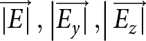 $\,\overrightarrow {\left| {{E_{}}} \right|} \,,\left| {\overrightarrow {{E_y}|} \,,} \right|\overrightarrow {{E_z}|} $ is the Electric field along the x, y, z directions, respectively, and
 $\rho $ is the mass density of the human tissue.
When the antenna is placed over the human body, the side lobes and the back lobes of the antenna get absorbed by the skin, fat and the muscle as they are directed into the body gets dissipated contributing to the high SAR value. The analyzed SAR value when antenna alone placed over the human body is 59.16 W/Kg for 1 g and 85.42 W/Kg for 10 g at 2.45 GHz and 15.13 W/Kg for 1 g and 26.47 W/Kg for 10 g at 5.9 GHz for 0.5 W input power. The higher SAR values at 2.45 GHz shows higher conductivity of the body at that frequency. The SAR value of the antenna alone placed over the human body is far more greater than the values limited by FCC and the ICNIRP. To enable it to be used for a longer time in the nearness of a human body, AMC is incorporated along the antenna to reduce the SAR value to its limits. The simulation results of the SAR analysis along with AMC is 1.105 W/Kg for 1 g and 0.169 W/Kg for 10 g at 2.45 GHz and 0.447 W/Kg for 1 g and 0.086 W/Kg for 10 g at 5.9 GHz for 0.5 W input power. Figure 20 shows the results of SAR analysis for antenna alone and for the antenna with AMC and their peak values are summarized.
Figure 19 compares the return loss characteristics of the antenna in free space, with AMC, and with AMC on the body, showing ability of AMC to preserve impedance matching and minimize frequency detuning in human proximity.
Comparison of the S parameters of antenna, antenna with AMC, on-body antenna with AMC.

SAR analysis of the antenna alone (top) and antenna with AMC (bottom) when placed near human at 2.45 and 5.9 GHz and their maximum SAR values for 0.5 W input power is summarized.

Effect of bending on antenna performance
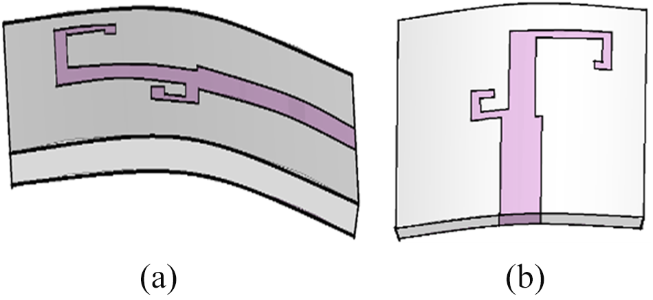
The WBAN slightly suffers deformation and the extent to which it bends when placed over the body depends on the material used. In this paper, Rogers 4534 substrate is used which is slightly flexible. Hence the performance of the antenna when slightly bent is analyzed using simulation tool. The designed antenna is bent along xy and xz planes. The antenna is bent around various radius of r = 90 mm, 100 mm, 110 mm and their scattering parameters are analyzed. Figure 21 renders the pictorial representation of the bending at various radius of curvature alone both the xy and xz planes. Figure 22 shows the functioning of the antenna when bent along various axis with abovementioned radius. The results are summarized in Table 6.
Antenna bent along (a) xy plane and (b) xz plane.

Performance of the antenna under bent condition along (a) xy and (b) xz plane with radius of curvature r = 90 mm, 100 mm, 110 mm and at flat condition.

Summary of Figure 22

The lower band of the antenna remained stable with very negligible frequency shift. The upper band shows slight variations when observed in both xy and xz planes. This confirms the antenna’s resilience. The performance of the proposed antenna is studied with various research works and is summarized in Table 7. Comparing to the state of art works, the proposed work is having better performance in terms of gain, bandwidth, return loss and SAR.
Comparison of this work with those of the work presented in the literature

Conclusion
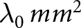
This work is about the design and the performance evaluation of AMC backed compact dual-band antenna of a unique structure for WBAN applications. The antenna is tailored using CMA by studying the eigenmodal characteristics to operate at 2.45 and 5.9 GHz with improved radiation characteristics and impedance matching and smaller area of about 0.286 $\,{{{\lambda }}_0}$ x 0.265
 $\,{{{\lambda }}_0}\,m{m^2}$, where
 ${{{\lambda }}_0}$ is the free space wavelength at 2.45 GHz. The key focus of this work was to enhance the performance of the antenna by addressing issues like back radiation lobes and frequency detuning effect at human proximity. The antenna shows resilience to bending, but with the presence of back radiation contributing to high SAR values was considered as a significant drawback. Hence, the AMC was utilized to mitigate the back radiation through its zero-degree reflection behavior and enhance the antenna performance. It is observed that the measured gain has a significant increase of 115% and 86.5% at the lower band and the upper band, respectively, and a 21% and 26.9% increase in bandwidth at the lower and the upper bands. When the antenna and AMC were mounted on the human body, AMC prevented the frequency detuning effects and maintain low SAR values below the standard limits. With all the novelty such as a unique structure, smaller size, high gain, better bandwidth, lower SAR values and resilience for bending ensures that the designed antenna is safe for prolonged used on human body for continuous monitoring of the patient.
Author contribution
S.J. contributed to the conceptualization, methodology, investigation, formal analysis, and writing – original draft of the manuscript. V.K. provided supervision, resources, and contributed to writing, review, and editing of the manuscript. Both authors have read and approved the final manuscript.
Funding statement
The authors received no financial support for the research, authorship, or publication of this article.
Conflict of interest
The authors declare that they have no conflicts of interest related to this work.

Sherene Jacob is a Research Scholar in the Department of Electronics and Communication Engineering at Thiagarajar College of Engineering, Madurai, India. She received her Master’s degree in Communication Systems and her Bachelor’s degree in Electronics and Communication Engineering. Her research interests include antenna design, bio-telemetry, bio-electromagnetics, and numerical methods for analyzing electromagnetic interactions in biological media. She works on compact antenna structures for implantable and body-centric medical devices, with emphasis on in-body communication performance. Her goal is to develop reliable, miniaturized RF solutions that enhance wireless communication for emerging biomedical and healthcare technologies.

Vasudevan Karuppiah is an Associate Professor in the Department of Electronics and Communication Engineering at Thiagarajar College of Engineering, Madurai, India. He holds a Ph.D. degree in Signal Integrity, with expertise spanning antennas, RF systems, microwave engineering, and biomedical applications of electromagnetics. His research interests include high-performance RF design, electromagnetic compatibility, and the development of reliable communication solutions for modern electronic and biomedical systems. He has guided postgraduate and research scholars, contributed to multiple publications, and is actively involved in advancing practical and industry-relevant solutions in the areas of microwave engineering.