

Introduction
Cochlear implantation has become the standard of care for hearing rehabilitation in patients with severe to profound sensorineural hearing loss. As of 2010, around 219 000 cochlear implants have been implanted worldwide.1 Advances in cochlear implant technology and surgical technique have improved the operative procedure and auditory outcomes of patients undergoing implantation. In particular, key advances in the device itself,Reference Carlson, Driscoll, Gifford and McMenomey2 the surgical procedure and intra-operative monitoring have all improved efficiency and allowed more streamlined management. Examples of such advances include a smaller incisionReference Magnus, Rivas, Tsai, Haynes and Roland3, Reference Flint, Haughey, Niparko, Richardson, Lund and Robbins4 and modifications to secure the receiver-stimulator. With regards to the latter, procedures that previously involved drilling wells or suture fixation often now simply entail the creation of a tight temporalis pocket.Reference Cohen, Roland and Fishman5, Reference Balkany, Whitley, Shapira, Angeli, Brown and Eter6
Most intra-operative or routine post-operative tests, including imaging and audiometric testing, are conducted to alert surgeons to a malfunctioning or misdirected device. Imaging, particularly X-ray, has been traditionally recommended,7 but the utility of routine post-operative X-ray was recently debated in the literature.Reference Copeland, Pillsbury and Buchman8 Fluoroscopy is used at certain centres and has been found to detect array misdirection in anatomically complex cases,Reference Coelho, Waltzman and Roland9, Reference Fishman, Roland, Alexiades, Mierzwinski and Cohen10 but is not used routinely because of the size, expense and operative disruption of the actual device. Intra-operative temporal bone computed tomography (CT) is also employed for particularly difficult cases, such as congenital ear deformities.Reference Yuan, Song, Chai, Shen, Han and Liu11 However, most believe that implant position can be detected easily with X-ray, and does not necessitate the added cost, time and radiation associated with CT scanning.Reference Shpizner, Holliday, Roland, Cohen, Waltzman and Shapiro12
Electrode impedances and neural response telemetry have also been used to confirm the proper position and functioning of the device. These methods can provide objective data for post-operative mapping, and act as a counselling tool at the conclusion of the surgical procedure.Reference Shapiro and Bradham13 However, the results can be misleading, as abnormal test components do not reflect post-operative function, while normal test results can still occur with misplaced electrodes.Reference Mason14
Even with the aforementioned recent advances, improper positioning of the electrode array has been reported in 0.17–2.12 per cent of cases.Reference Tange, Grolman and Maat15 This study reports on 5 of our patients and 11 patients in the literature with electrode arrays that were misplaced into the vestibular labyrinth. We conclude that the simplest and most reliable precaution against improper positioning is the routine use of intra-operative plain film X-ray.
Case report
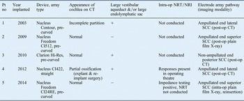
We present five patients with cochlear implant arrays that were misdirected into the vestibule or a semicircular canal. This study was approved by the institutional review board of our institution. Four patients who underwent cochlear implantation for profound sensorineural hearing loss were found on post-operative imaging to have misdirected electrode arrays into a semicircular canal (Table I). The fifth patient underwent intra-operative plain film radiography and was found to have a misdirected electrode array, which was corrected in the same operation (Table I).
Misdirected cochlear implant array case series data

Misdirection in patients numbered 1–4 was detected post-operatively. Misdirection in patient number 5 was detected intra-operatively on plain film X-ray and corrected. Pt no = patient number; CT = computed tomography; op = operative; NRT = neural response telemetry; NRI = neural response imaging; ‘+’ = present; ‘−’ = absent; SSC = semicircular canal
Pre-operative CT imaging did not indicate any insertional problems. Possible associated malformationsReference Fishman16 were large vestibular aqueducts and/or large endolymphatic sacs, affecting three of the patients. One of these patients also had incomplete partition, and another had a partially ossified cochlea. The remaining patients had patent cochleae without inner-ear abnormalities.
During the actual operations, there were no difficulties with electrode array insertion. Three of the five patients had an anterior-inferior cochleostomy performed. The patient with the cochlear ossification underwent attempted scala vestibuli insertion, based on the findings seen on pre-operative imaging. For this case, the electrode insertion went smoothly and appeared to be entering into the appropriate place. In the final case, a round window insertion was performed. In four of the five cases, the electrode arrays employed were pre-curved, and in one case the electrode array was straight.
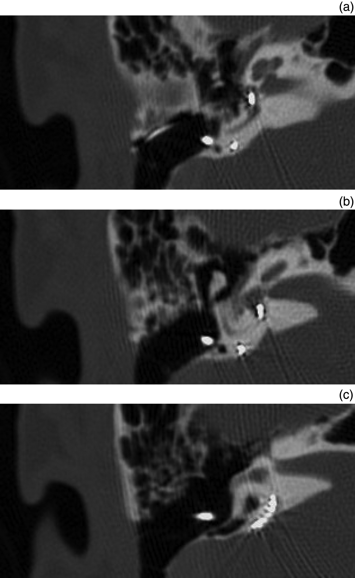
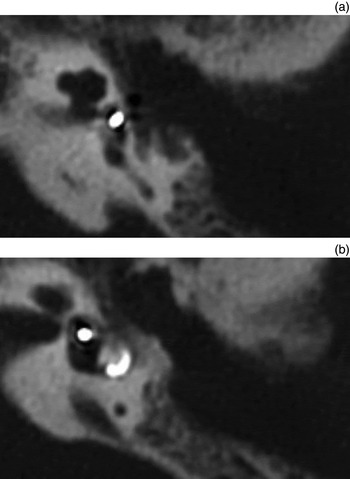
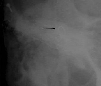
Intra-operative neural response telemetry or impendence testing was performed in two cases, with limited responses for both. Only one of these patients underwent intra-operative plain film radiography, which prompted reinsertion. Misdirection in the other four cases into the semicircular canals was seen post-operatively on plain film X-ray or CT scans (Figures 1–3).
(a) – (c) Serial axial temporal bone computed tomography images showing the electrode array pathway (patient number 3). The entrance is into the basal turn of the cochlea, next turning 180°, then entering the vestibule and non-ampullated end of the posterior semicircular canal. Note the enlarged vestibular aqueduct and normal anatomy of the cochlea.

(a) & (b) Serial axial temporal bone computed tomography images from patient number 1. Again, the electrode array enters the basal turn of the cochlea, turns 180°, and enters the vestibule and lateral semicircular canal via the ampullated end. Note the enlarged vestibular aqueduct and patent cochlea with an incomplete partition.

Intra-operative X-ray demonstrating S-shaped configuration of the electrode array inserted into the superior semicircular canal (arrow), as opposed to the normal helix of cochlear placement (patient number 5). This array was withdrawn and correctly redirected intra-operatively.

Literature review
A search of the English-language literature published from 1995 to 2013 was conducted using the following search terms: ‘cochlear implant position’, ‘malposition’, ‘misdirection’, ‘improper insertion’ and ‘complications’.
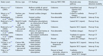
Eleven cases of electrode array misdirection into the vestibules or semicircular canals were identified (Table II).Reference Tange, Grolman and Maat15, Reference Mecca, Wagle, Lupinetti and Parnew17–Reference Ying, Lin, Oghalai and Williamson23 Four of the 11 patients had documented anatomical abnormalities. In one patient, patent but bulbous middle and apical turns can be seen in the CT images published in the article itself.Reference Mecca, Wagle, Lupinetti and Parnew17 In the second case, the article reports an ossified cochlea on imaging, but states that intra-operatively only the round window niche was obstructed.Reference Rotteveel, Proops and Ramsden20 One paper reported a case of anatomical abnormality observed at the time of surgery (ossified scala tympani), which led to an attempted scala vestibule insertion, and another case of abnormality only seen on closer inspection of the post-operative CT scan (incomplete spiral lamina at the apical turn), which is of unclear significance.
Previous reports of misdirected cochlear implant arrays

Eleven patients are reported. Five misdirections were detected on plain film X-rays. The remaining misdirections were detected by computed tomography post-operatively. CT = computed tomography; op = operative; NRT = neural response telemetry; NRI = neural response imaging; SSC = semicircular canal
None of these 11 reports give any information about the size of the vestibular aqueduct or the endolymphatic sac. Of the 11 cases reviewed, only 4 had documented malformations on imaging.
Only one case in the literature reported difficulty with insertion during operation.Reference Ramalingam, Ramalingam and Padmaja19 In the papers that reported the electrode array model employed, four of the arrays were pre-curved and one was a lateral wall array.
Intra-operative audiometric testing did not predict misdirection: seven patients underwent neural response telemetry, and four of these appeared to have responses. In one case, neural response telemetry responses were still absent after repositioning of the electrode array, but the patient went on to have good function of the implant.Reference Muzzi, Boscolo-Rizzo and Santarelli18
Three of the 11 cases of misdirection were found intra-operatively on plain X-ray with anteroposterior views of the head, and were corrected in that same procedure. Two of the 11 misdirections were detected by plain film X-ray post-operatively. In these cases, only the superior and lateral canals were cannulated. All misdirections reported in the English-language literature could be seen on plain film X-ray.
Discussion
Eleven cases of aberrant electrode array insertion into the vestibular labyrinth reported in the English-language literature were reviewed (Table II). No pre-operative anatomical variable that makes misdirection more likely was identified. These cases do not describe the vestibular aqueducts; however, the cochlea is described as being patent in most of these 11 cases. In our series, three of the five patients had enlarged vestibular aqueducts, and one patient had a patent cochlea with incomplete partition. Another patient had partial ossification of the basal turn, which made explantation and re-implantation surgery problematic; therefore, scala vestibuli insertion was attempted, which appeared to proceed smoothly.
It is interesting that three of the five patients in our series had enlarged vestibular aqueducts. When our case series and the cases reported in the literature were considered together, pre-operative imaging did not predict misdirection. Ten of the 16 patients had a normal cochlea pre-operatively, and only 6 patients had malformations. Intra-operatively, there were no clear warning signs of misdirection either. Only one of the insertions in the literature was reported to be difficult. Also, impedance testing was positive or neural response telemetry responses were present for six of the nine cases in which the technique was employed. It is believed that a response may still be elicited if the electrode array is in the vestibule.Reference Ying, Lin, Oghalai and Williamson23 Therefore, misdirection occurred even with normal pre-operative imaging findings, when insertion was smooth, and when impedance testing was positive and neural response telemetry responses were present.
In reviewing the images in our case series, the electrode arrays are entering the cochleostomy site and turning 180° from the basal turn insertion, and proceeding posterior-superior into the vestibule rather than anterior-inferior towards the middle turn (Figures 1 and 2). The array then enters the ampullated or non-ampullated end of any of the semicircular canals. There is no clear aetiology or anatomical obstruction seen on these images that indicates why the electrode array takes this course.
One probable explanation for the misdirection of the electrode array is a suboptimal angle of insertion. For example, when our fifth patient's implant was directed more anterior-inferiorly, the subsequent implant path was appropriate. Another potential cause for misdirection is the type of electrode array inserted. Considering all cases where implant type was known, 8 of 10 involved a pre-curved array. However, most of the literature cases reviewed did not report the model or type of implant used. Other possible explanations that have been cited in the literature include: an inadequate facial recess or inability to visualise the round window, improper placement of the cochleostomy, ossification of the cochlea, inner-ear malformations, and patient positioning.Reference Ying, Lin, Oghalai and Williamson23
All of the misdirected electrode arrays were detected using imaging, either intra-operatively or post-operatively. The majority of cases in our series and in the literature were detected after the patient had recovered from the surgery, and required a second operation. This delay in detecting the problem adds to morbidity and cost. In 1 of our 5 cases, and in 3 of the 11 cases reported in the literature, an intra-operative X-ray was performed and the implant was adjusted during the same procedure.
• Cochlear implant electrode arrays can be misplaced in an anatomically normal ear without the surgeon's awareness
• X-ray has been traditionally recommended to detect misplacement, but routine post-operative X-ray use was recently debated
• Intra-operative fluoroscopy and computed tomography scans can also detect array misdirection, but are less favourable because of time, cost and radiation
• Pre-operative imaging did not predict misdirection into vestibular labyrinth, and intra-operative imaging showed no clear misdirection warning signs
• Positive impedance tests and neural response telemetry responses were common, even when implant was misplaced
• Misdirection was detected and corrected in same procedure using intra-operative X-ray; hence, routine intra-operative X-ray is recommended for proper placement
Although some advocate restricting the use of X-rays to anatomically difficult cases,Reference Copeland, Pillsbury and Buchman8 it is clear from these cases that the electrode can often be misplaced in an anatomically normal ear, without the surgeon being aware. Intra-operative CT or fluoroscopy have been suggested to ensure good insertion, but these are too cumbersome, time consuming and expensive to employ for every implantation. A recent retrospective review analysed the use of intra-operative electrophysiological monitoring and intra-operative Stenver's view plain film radiography, and found that only the radiological findings altered surgical management.Reference Cosetti, Troob, Latzman, Shapiro, Roland and Waltzman24 We posit that plain X-ray anteroposterior views of the head are inexpensive and fast to carry out, and can be used routinely for every implantation.
Conclusion
Sixteen cochlear implant electrode arrays that were misdirected into the vestibular labyrinth are reported and reviewed here. There appears to be no consistent pre-operative risk factors or anatomical variables present on CT scans that indicate predisposition to this complication. Intra-operative audiometric testing is inconsistent in its ability to detect an electrode array within the vestibule or a semicircular canal, and there is often no reported difficulty in electrode insertion. We therefore recommend employing intra-operative X-ray as a routine method of ensuring proper placement.