1. Introduction
Nikola Tesla first demonstrated wireless power transfer (WPT) in the 1890s [Reference Tesla1]. Though the technology did not immediately find its way into any applications, WPT has progressed tremendously and is now making its way into every aspect of our daily lives. Current WPT standards and techniques cater to consumer electronics and the automobile industry but have not been widely implemented in medical devices; today, many medical devices still use galvanic cables or large bulky batteries. Magnetic resonance imaging (MRI) is one such medical diagnostic modality that can benefit significantly from WPT. MRI commonly uses radiofrequency (RF) surface coil phased arrays as receivers that are placed close to the patient. The number of channels used to form these phased arrays is increasing to improve the speed of MRI scans and increase patient throughput in hospitals. Each channel of the phased array requires one coaxial and one DC cable to communicate, transfer image data, and power the coil components. Therefore, an increase in the number of channels currently increases the numbers of cables, by a factor of three. The large size of the cables can cause patient discomfort, delays as the technician positions the bulky cables safely around the patient, and in a worst-case scenario, cause patient harm.
Several wireless solutions are being proposed to transfer data [Reference Riffe, Twieg, Gudino, Blumenthal, Heilman and Griswold2, Reference Agarwal, Jegadeesan, Guo and Thakor3]. However, the research for wirelessly providing power is still in its infancy. Implementing a WPT system will improve the feasibility of higher channel count RF surface coils by eliminating galvanic cables needed for power, making RF surface coils safer, reliable, more comfortable for the patient and easier to use by the operator. One such system has been discussed by Byron et al., [Reference Byron, Robb, Stang, Vasanawala, Pauly and Scott4]. By adopting the WPT standards and techniques available in the market, this technology may mature sooner. Nevertheless, this task is not trivial, as the components used in commercially available WPT systems cannot operate safely and effectively in the strong electromagnetic fields of the MRI system. This work focuses on achieving electromagnetic compatibility of the antennas commonly used in the WPT system inside the MRI system.
Traditional multi-turn antennas [Reference Ganti, Lin, Wynn and Ortiz5] popularly used in the wireless power community are incompatible with the MRI system. The benefits that multi-turn antennas possess are diminished as they may adversely affect the patients in the MRI system. The authors in [Reference Byron, Robb, Stang, Vasanawala, Pauly and Scott4], discussed a single-turn wireless power transmitting (TX) antenna made of copper tape and tubing. The choice of a single-turn antenna is dictated by the need for galvanically connected filter circuits to prevent unwanted RF currents from being induced during the MRI transmit mode.
The focus of this paper is to propose a novel solution to the electromagnetic compatibility issues that the WPT transmitting (TX) and receiving (RX) antennas present to patient safety and the signal to noise ratio (SNR) of the diagnostic image. This work presents the application of a filter circuit for use on WPT antennas, referred to here as a “floating filter” as it is not galvanically connected to the antenna. Due to the nature of its construction, this filter circuit can be applied to antennas with multiple turns under certain conditions. The concept for the filter circuit was previously introduced by Ganti et al., [Reference Ganti, Lin, Wynn and Ortiz5] for WPT in MRI systems, and the observable distortion caused by the antennas reduced to 14% from an unsafe level of 32%. This paper builds upon the concept and demonstrates a distortion of less than 5% within the imaging volume. This paper also discusses the advantages of isolating the WPT antennas from the RF receive surface coils using the filter circuit. In the sections that follow, the basics of MRI, a method to measure the distortion caused by conductors in the MRI system (called B 1 distortion), challenges of implementing a WPT transfer system, and a method to achieve electromagnetic compatibility of WPT antennas for RF surface coils used in MRI are discussed. The results from the test bench and MRI experiments are explained and discussed in detail. The analysis highlights the effectiveness of the floating filter circuit in achieving electromagnetic compatibility of not only a single turn but also multiple-turn WPT antennas in the MRI system.
2. Background
2.1 MRI basics
MRI is a high-fidelity imaging platform that employs strong magnets to exploit the quantum spin state of protons (1H), by spatially locating variations in density of protons within a volume of interest. When a subject is placed in a strong static magnetic field (B 0), the magnetic moments of these protons align with the direction of the B 0 field and precess around the magnetic field, B 0, at a frequency known as the Larmor frequency. The Larmor frequency is linearly proportional to the strength of the magnetic field, B 0, and for a proton, under 1 T static magnetic field, it is about 42.58 MHz [Reference Haacke, Brown, Thompson and Venkatesan6]. This relationship is commonly referred to as the gyromagnetic ratio, γ. MRI systems with B 0 of 1.5 and 3.0 T, therefore, operate at (approximately) 64 and 128 MHz, respectively, and are the most commonly used systems for diagnostic imaging. To acquire an image, the protons are first excited to a higher energy state, by applying an RF magnetic field (B 1), at the operating frequency (64 or 128 MHz) using high power amplifiers capable of generating several thousand watts of transmitted power (MRI transmit mode). After a predetermined time, the RF amplifiers are turned off (entering MRI receive mode), and the protons return to their initial energy state, releasing RF energy; a process called “relaxation.” The emanated signal is very weak and decays rapidly with distance as 1/r 3. Therefore the signal needs to be detected using RF surface coils (near field, magnetic field antennas) that are placed as close as possible to the volume of interest. The received signal is amplified and transmitted through cables to the MRI system's computer for processing and image reconstruction [Reference Caverly7].
2.2 RF surface coils
The receiving RF surface coils are electrically short coils made from a single turn of copper and operate at the same frequency as the MRI system's transmitting frequency. The receiving coils are placed very close to the volume of interest and in many cases, conform to the shape of the human body for minimizing signal loss. As the coils are positioned near the human body and are tuned to the same frequency as the high power MRI transmitter, they need to be decoupled from the B 1 field during the MRI transmit mode. Decoupling is necessary to reduce currents in the surface coil loop antenna induced by the transmit power amplifiers protecting the patient and the sensitive low-noise amplifier (LNA) of the RX chain. Decoupling from the MRI transmit phase is usually accomplished by employing PIN diodes as a switch [Reference Ganti, Ortiz, Wynn, Lin and Duensing8].
During operation, each surface coil consumes on average 300 mW of power. The first-stage LNA essential for amplifying the weak RF signal and obtaining images with a high SNR consumes 150 mW while the decoupler also consumes around 150 mW. Galvanic cables deliver the required power from the MRI system. Figure 1 shows the schematic of a single MRI RF surface receive coil, also sometimes referred to as a “channel.” In modern RF surface coils, multiple channels are combined to form a phased array to enable parallel imaging techniques and increase the image acquisition speed.
Schematic of an RF surface coil.

RF surface coil phased arrays of 32 channels and above have become common, and for cardiac imaging research Hardy et al., [Reference Hardy, Giaquinto, Piel, Rohling, Marinelli, Blezek, Fiveland, Darrow and Foo9] even developed a 128 channel phased array. Each channel of the RF phased array requires at a minimum one galvanic cable to communicate, transfer power, and collect data. The physical size of the galvanic cable bundles is a limitation for higher channel-count phased arrays because not only are the cables bulky; they can become susceptible to unwanted currents that are induced during the MRI transmit mode. If the cables are not carefully managed, the induced currents are likely to distort imaging and may even cause severe RF burns to the patient. Long cables can reduce the SNR of the final image [Reference Peterson, Beck, Duensing and Fitzsimmons10]. Due to the limited space inside the MRI system, care must be taken to maintain proper placement of the patient and RF surface coil, and to separate the cables from the patient.
2.3 WPT in MRI
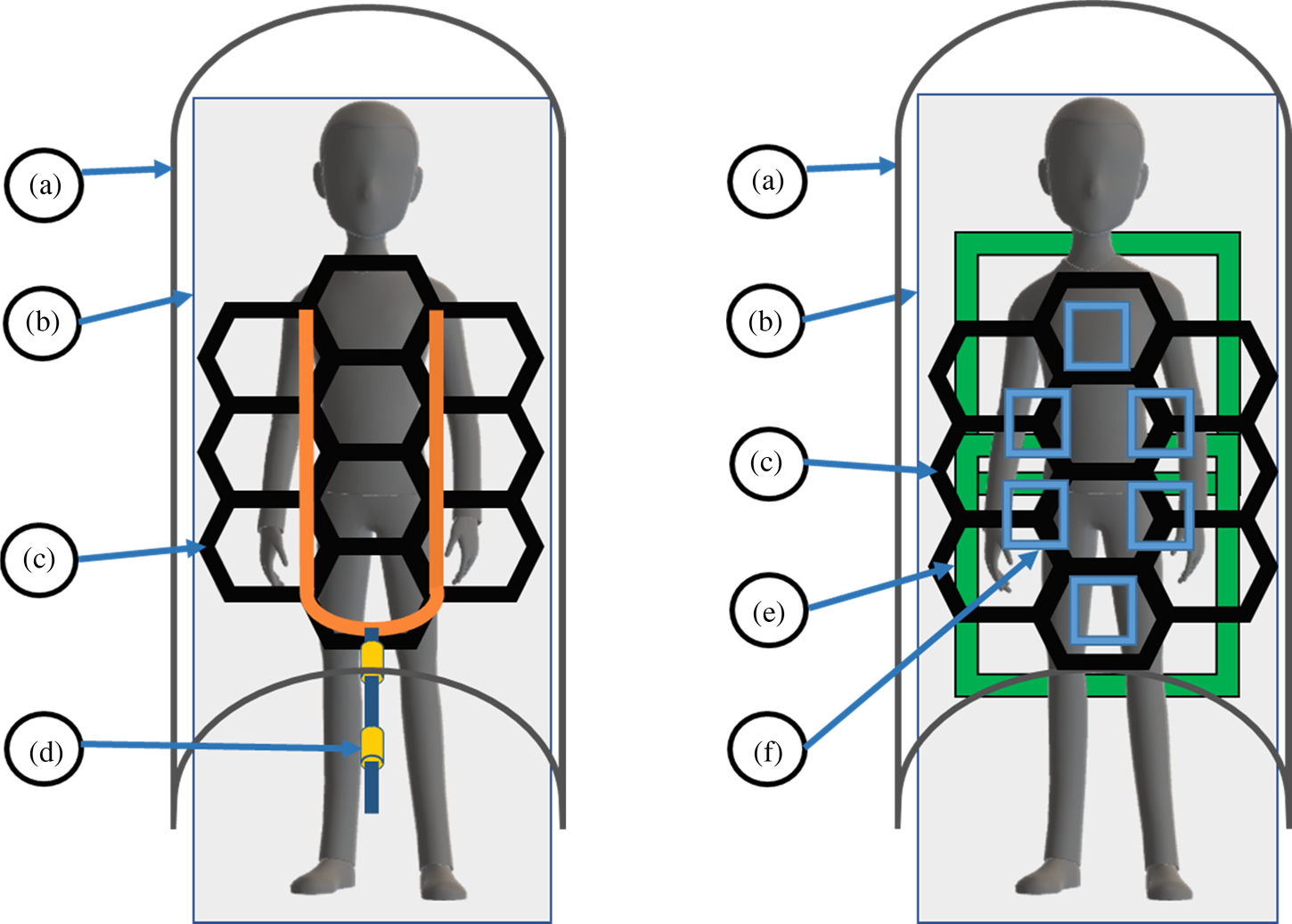
Figure 2 illustrates the current and proposed ways of powering RF surface coils in the MRI system, by using cables and via a WPT-based system. In the proposed WPT system, the WPT TX antenna is placed inside the patient table, while the WPT RX antenna is enclosed within the RF surface coil [Reference Byron, Robb, Stang, Vasanawala, Pauly and Scott4]. Though single or multiple large WPT TX antennas can be used, a unique set of WPT RX antennas must be designed depending on the geometry of the RF surface coil. A WPT system eliminates the need for a system cable (Fig. 2(d)) to be present within the MRI system close to the patient.
Top-down view of the MRI system. (Left) The current state of the art representation. (Right) Proposed WPT system. The building blocks are: (a) MRI system that is also the MRI transmitter, (b) patient table, (c) MRI receive coil (RF surface coil), (d) system cable, (e) WPT TX coils present in the patient table, and (f) WPT RX coils present in the MRI receive coil.

2.4 WPT antenna for the MRI system
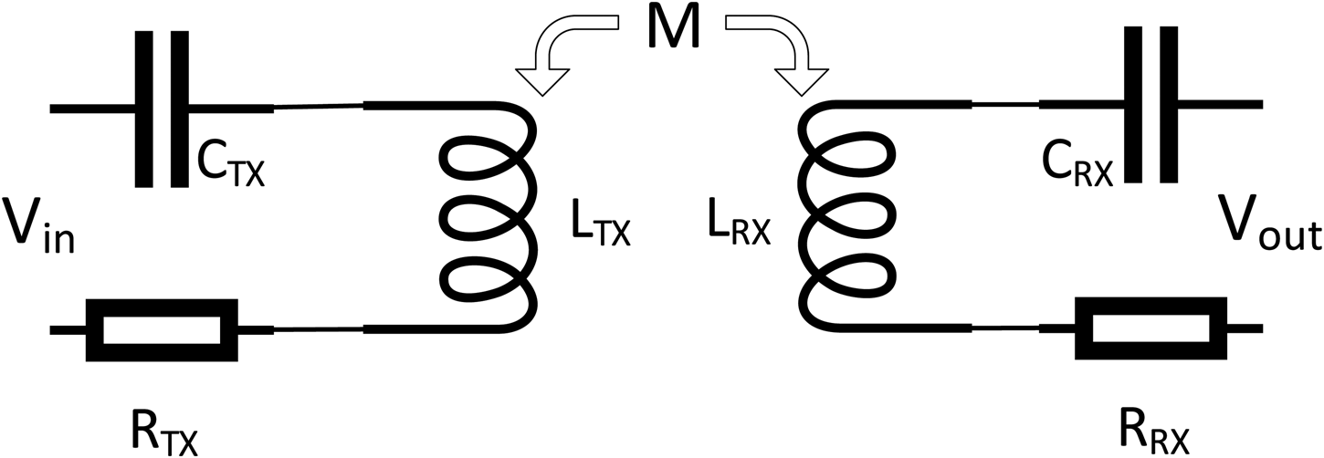
Figure 3 shows a schematic for an inductively coupled WPT system operating at resonance. The efficiency of the system is calculated by measuring the voltages and currents at inputs and outputs. The voltages and currents are related by equation (1):
 $$\eqalign{\left( {\matrix{ {V_{in}\lpar {\,j\omega} \rpar } \cr {V_{out}\lpar {\,j\omega} \rpar } \cr}} \right) = &\left( {\matrix{ {R_{TX} + j\omega L_{TX} + \displaystyle{1 \over {\,j\omega C_{TX}}}} \hfill & {\,j\omega M} \hfill \cr {\,j\omega M} \hfill & {R_{RX} + j\omega L_{RX} + \displaystyle{1 \over {\,j\omega C_{RX}}}} \hfill \cr}} \right) \cr & \times \left( {\matrix{ {I_{in}\lpar {\,j\omega} \rpar } \cr {I_{out}\lpar {\,j\omega} \rpar } \cr}} \right)} $$
Equivalent circuit of an inductively coupled WPT system.

In the above equation, ω = 2 × π × f WPT, where f WPT is the WPT system's operating frequency, V in, I in, and V out, I out are the input and output voltages and currents in the WPT TX antenna and RX antennas, respectively. R TX, L TX, C TX, R RX, L RX, and C RX are the loss resistance, inductance, and series compensating capacitor, (to maintain resonance) on the TX and RX WPT antennas. M is the mutual inductance between the TX and RX antennas.
At resonance jωL i = −(1/jωC i), i = TX or RX and (1) reduces to
 $$\left( {\matrix{ {V_{in}\lpar {\,j\omega} \rpar } \cr {V_{out}\lpar {\,j\omega} \rpar } \cr}} \right) = \left( {\matrix{ {R_{TX}} & {\,j\omega M} \cr {\,j\omega M} & {R_{RX}} \cr}} \right) \times \left( {\matrix{ {I_{in}\lpar {\,j\omega} \rpar } \cr {I_{out}\lpar {\,j\omega} \rpar } \cr}} \right)$$
When a load, R load, is connected at the output of the receive antenna, the efficiency of the system can be calculated using equation (3).
 $$\eta _{coil} = \displaystyle{{\omega ^2M^2R_{load}} \over {\lpar {R_{TX}\lpar {R_{load} + R_{RX}} \rpar + \omega^2M^2} \rpar \lpar {R_{load} + R_{RX}} \rpar }}\; \; $$
For a load R load, the maximum efficiency can be calculated by differentiating equation (3) with respect to the R load, and equating it to zero, as shown in (4).
 $$R_{RX}^2 + \; \displaystyle{{\; \omega ^2M^2R_{RX}} \over {R_{TX}}}-\; R_{load}^2 = 0$$
By simplifying equation (4) further, a mathematical result for the ideal load to achieve a high efficiency is given by (5).
 $$R_{load} = \; R_{RX}\sqrt {1 + \; \displaystyle{{\omega ^2M^2} \over {R_{RX} \times R_{TX}}}} $$
From equation (5) we see that for a particular load, R load, the maximum transfer efficiency depends on the parasitic resistances R RX and R TX, the frequency of operation, and the mutual inductance between the transmitting and receiving antennas. The parasitic resistances, R RX and R TX, caused due to copper losses are dependent on the construction of the antenna. The efficiency of the circuit can be improved by increasing the frequency or mutual inductance, M, between the transmitting and receiving antennas. Traditional wireless power antennas constructed using multiple turns to achieve higher mutual inductance may have a total length longer than the quarter wavelength (λ/4) of the MRI operating wavelength and can support an unwanted current induced during the MRI TX phase. A filter should be placed at the current maxima to reduce the induced currents [Reference Peterson, Beck, Duensing and Fitzsimmons10]. However, placing a filter on a traditional multi-turn WPT antenna is not trivial because of the need for multiple galvanic connections.
3. Research methods
In this section, the experiments used for proving the need and effectivity of a filter circuit for achieving electromagnetic compatibility are introduced. These experiments were performed both on the test bench and in the MRI system. Since the MRI system operates in two modes, transmit and receive, the experiments were designed to test the performance of the filter in isolating the WPT antennas from the high-power MRI transmit signal and preventing B 1 distortions. In the MRI receiving mode, the filter must prevent each channel of the RF surface coils from coupling with the WPT antennas to prevent parasitic losses and, therefore, losses to SNR. These tests and results are applicable for evaluating both the TX and RX WPT antennas. The analysis, construction, simulation, and experiments of the floating filter are described in the following sections.
3.1 Simulations
Simulations are performed in high-frequency structure simulator, Ansoft HFSS to determine the ideal length of the filter circuit and to study the effect of the filter on the magnetic field generated by the WPT antenna.
3.2 MRI transmit mode (B 1 distortion)
During the transmit portion of the MRI cycle, the transmit resonator must distribute the transmitted power uniformly into the patient to achieve high image quality. A disturbance in the uniformity of the RF transmit field is visible in the resulting image and causes undesirable image distortions called “artifacts.” A B 1 distortion artifact may form when conductors placed inside the MRI system behave like antennas themselves, supporting currents induced by the RF transmit field. The current induced on the conductors creates a field which is superimposed over the system's RF magnetic field, the B 1 field, creating an area of over- or under-emphasis (bright or dark spots) in the resulting image. An image distortion caused due to the disturbance of the RF magnetic field is known as B 1 distortion and is measured by examining changes to pixel intensity in the final reconstructed MRI image. The distortion caused by the electronics within a device under test (DUT) is measured by performing the same scan with and without the DUT present and measuring the difference in pixel intensity between the images. The variation in image uniformity is quantified using profile graphs that show a change in the intensity along a line drawn through uniform and non-uniform parts of the image. The B 1 distortion is specified in terms of a percentage change. Coil designers strive for a B 1 distortion of less than 5% [Reference Taracila, Chan and Robb11]. The distortion can be calculated using (6).
 $$\eqalign{{\rm Distortion\;} \lpar \% \rpar = \; \displaystyle{{{\rm Max}\,{\rm Pixel}\,{\rm Intensity}-{\rm Min}\,{\rm Pixel}\,{\rm Intensity}} \over {{\rm Max}\,{\rm Pixel}\,{\rm Intensity}}} \times 100}$$
3.2.1 Evaluating performance on the test bench
The performance of the filter is measured on the bench using two current injection probes to perform an S21 measurement. The first of the probes is connected to Port 1 of a network analyzer that induces a current onto the WPT antenna. The second current injection probe is attached to a different leg of the antenna and connected to Port 2 of the network analyzer. The measured S21 without the application of a filter will be close to 0 dB, as the attenuation is limited to losses in the antenna itself. With the filter applied, increased attenuation will be evident within some tuned band of frequencies.
3.2.2 Evaluating performance in the MRI system
The performance of the filter is measured in the MRI system by performing the B 1 distortion test, as described in the section above. A phantom used for this test mimics the human body and acts as a signal source when excited by the MRI system's transmitter. The scan parameters required to perform this test in a Philips MRI system are given in the Appendix.
3.3 MRI receive mode
As discussed in the sections above, each element of the MRI receives phased arrays is very sensitive in the RX band of interest for obtaining high SNR images. When a WPT antenna is placed near the RF surface coil, SNR is likely to be affected both by parasitic changes in frequency of the tuned circuits and also by directly acting as a coupled noise source. While coupling can be inductive and capacitive, due to the size of the elements involved the inductive coupling effects will dominate. A worst-case positioning of the WPT antenna is shown in Fig. 4. Filters applied to the WPT antennas are intended to alleviate the problems discussed above. The high impedance of the filter circuit attenuates the current at the MRI frequency, reducing inductive coupling, and minimizes the loss in SNR caused by the presence of the WPT antenna.
A worst-case positioning of a series compensated WPT antenna (c) on a two-channel phased array (a) and (b).

3.3.1 Evaluating the performance on the test bench
Evaluating the shift in the tuned frequency of an MRI coil, caused by the WPT antenna is carried out by using an RF surface coil and measuring the frequency response of the surface coil with and without the WPT antenna. For this experiment, an S21 measurement is performed on a two-channel phased array by injecting power into the MRI receive antenna using a flux probe (a small magnetic loop probe) and measuring the response at the output of the LNA.
3.3.2 Evaluating the performance in the MRI system
In the MRI system the effect of the WPT antenna on the receive performance is studied by performing an MRI scan and measuring the SNR of a phased array with, and without, the WPT antenna present. A phased array is placed on a phantom in the MRI system, and a spin-echo sequence is used to acquire an image, establishing the baseline, and is repeated with the WPT antenna present. The acquired images are used to study the effect of the WPT antenna on the SNR. The experiment is repeated for three cases – (i) without the WPT antenna, (ii) with WPT antenna and without the filter, and (iii) with the WPT antenna and the filters.
3.4 WPT system tests
The main focus of this paper is to demonstrate the electromagnetic compatibility of the WPT in the MRI system when a novel filter circuit is employed. The optimization of the WPT system for achieving high transfer efficiencies is out of scope for this paper and will be studied in the future. The transfer efficiency of the WPT system is measured with and without the presence of filter circuits at various distances. This experiment is performed on a single- and multi-turn WPT antenna to establish the need for a multi-turn antenna and the ability of the filter to work with on multi-turn antennas.
4. B 1 distortion of a commercially available WPT antenna
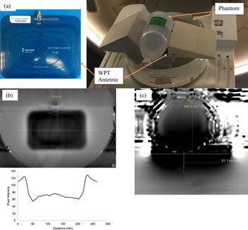
A commercially available TX antenna compatible with an A4WP Class D ZVS wireless power evaluation kit (operating at 6.78 MHz) by EPC corporation was placed in the MRI system, and a B 1 scan was performed by placing the antenna on a phantom as shown in Fig. 5(a). The B 1 distortion was measured using the procedure described above, and the results are shown in Figs 5(b) and 5(c). A distortion of greater than 50% was measured in Fig. 5(b). This distortion was not only present at the surface of the phantom but, as seen in Fig. 5(c), also penetrated the surface of the phantom. A distortion of greater than 50% will not only distort the diagnostic image but may also represent a danger to the patient.
(a) Setup for measuring the B 1 distortion in the MRI system – the antenna is sandwiched between two phantoms, (b) the B 1 distortion of the traditional WPT antenna, and (c) depth of distortion into the phantom.

5. Floating filter
5.1 Theory
The B 1 distortion and coupling caused by WPT antennas can be solved by using a band-stop notch filter. In its most basic form, the band-stop filter can be an LC tank circuit resonant at the same frequency as the MRI system's operating frequency. Figure 6(a) shows the current induced on a conductor. A current maximum is present at every half wavelength, so a filter circuit at every half wavelength will ensure proper control of the induced currents. The equivalent circuit of the filter circuit is shown in Fig. 6(b).
(a) Current induced on a conductor placed in the MRI system and (b) simple schematic of the filter circuit.

An LC filter is constructed utilizing a similar concept used for making cable baluns in the MRI system [Reference Ganti, Ortiz, Wynn, Lin and Duensing8 Reference Hardy, Giaquinto, Piel, Rohling, Marinelli, Blezek, Fiveland, Darrow and Foo9]. The WPT antenna's conductor can be used to form a solenoidal inductor required to function as the inductor of the LC filter. Alternatively, the WPT antenna may be cut to place a solenoid made with a different material in series. A filter constructed in this way has a notch response and poses a high impedance to the MRI system's operating frequency while the low-frequency wireless power signal remains relatively unaffected. However, both the methods described above add unacceptable complexity to the antenna design and manufacturing.
The floating filter proposed in this paper, on the other hand, is not physically attached to the antenna, but instead provides the necessary blocking impedance by coupling inductively to the antenna conductor. The term “floating” is used because the filter and the antenna are not physically connected. Although it could also be called a magnetically coupled filter, the word “magnetic” is purposely avoided to prevent confusion with the WPT system and MRI system both using magnetic fields for operation. The equivalent circuit of the floating filter attached to the WPT antenna is shown in Fig. 7.
Equivalent circuit of the floating filter attached to the WPT antenna.

Here V is the voltage induced by the MRI system and is proportional to the frequency (ω = 2πf), the magnitude of the MRI magnetic field (B 1), and the area of the WPT antenna (A). It is given by equation (7).
 $$V = B_1.A.\omega $$
C ant is the series compensating capacitor in the WPT antenna, L ant is the inductance of the antenna, and M is mutual inductance between the WPT antenna and the floating filter. L filter is the inductance of the filter, and C filter is the parallel capacitance used to tune the structure to the MRI system's frequency.
The floating filter circuit works by creating an impedance and to the current induced by the MRI transmit pulse, I 1 in the WPT antenna. This condition can be utilized to solve the system of equations in (8) for obtaining the desired requirements of the floating filter circuit.
 $$\left( {\matrix{ V \cr 0 \cr}} \right) = \left( {\matrix{ {Z_{ant}} & {\,j\omega M} \cr {\,j\omega M} & {Z_{\,filter}} \cr}} \right) \times \left( {\matrix{ {I_1} \cr {I_2} \cr}} \right)$$
where Z ant is the impedance of the WPT antenna, and Z filter is the impedance of the filter at the MRI system's frequency of operation. Solving (8) for current I 1, results in (9)
 $$I_1 = \displaystyle{{Z_{\,filter} \times V} \over {Z_{\,filter}Z_{ant} + \omega ^2M^2}}$$
The conditions for minimizing the current are obtained by differentiating equation (9) with respect to impedance of the floating filter (Z filter) and the mutual inductance M between the WPT antenna and the floating filter. Differentiation with respect to Z filter, and equating to zero results in equation (10).
 $$\displaystyle{{\omega ^2M^2} \over {{\lpar {Z_{ant}Z_{\,filter} + \omega^2M^2} \rpar }^2}} = \; 0$$
For satisfying (10) Z filter must tend to infinite. Alternatively, from the equation, it is seen that Z ant, could also possibly be made to have a high impedance at the MRI system resonance frequency, yielding a WPT antenna that transmits wireless power and blocks induced currents by the MRI system. However, the construction of such a system would be a tough challenge, and the analysis is out of the scope of this work.
The second set of conditions is obtained by differentiating equation (9) with respect to the mutual inductance (M) and equating to zero resulting in (11).
 $$\displaystyle{{2\omega ^2Z_{\,filter}V} \over {{\lpar {(Z_{ant}Z_{\,filter})/M + \omega^2M} \rpar }^2}} = \; 0$$
From the conditions derived in (10), Z filter is non-zero. The equation reduces to zero when the mutual inductance M tends to infinite, which supports the conditions derived from equation (10), because, impedance scales with inductive (or capacitive) reactance, so a large inductance is preferred. A large inductance couples more effectively to the WPT antenna, increasing the mutual inductance. Since the performance of the floating filter depends on the filter's ability to couple inductively with the antenna's conductor, the filter performance reduces when it does not couple effectively with the WPT antenna. Several methods can be utilized to improve the coupling between the filter and the antenna conductor. The inductance can be increased by making the filter circuit longer or by increasing the cross-sectional area of the filter. However, there is a limitation as the area of the filter circuit cannot be increased indefinitely; otherwise, the circuit becomes bulky and impractical. The performance of the filter is also related to the loss present in the LC filter circuit. The loss is a result of the dielectric material used and the resistive loss of the metal conductors. It should also be noted that the addition of the floating filter changes the inductance of the WPT TX antenna, and therefore the TX antenna must be impedance-matched to the power amplifier after applying the filter circuit. The equivalent circuit of the antenna with the filter applied is presented in Fig. 8. It can be seen that the inductance of the antenna is reduced by the mutual inductance, and C ant needs to be adjusted after the application of the filter.
Equivalent circuit of the WPT antenna with the filter attached.

In Fig. 9, a physical representation of the floating filter is shown, as it would be situated around the WPT antenna's conductor. The two concentric cylinders are made of a conductive material, such as copper, and both the ends of the cylinders are connected and tuned to the MRI system's frequency using capacitors (represented here by the white square blocks). In this representation, air is used as a dielectric, but other options certainly exist.
A physical representation of the filter applied to the conductor.

5.2 Simulations in HFSS
A model of the floating filter was constructed and simulated in HFSS. The performance was measured by wrapping the floating filter around a 4 mm diameter copper bar (with planar return) and measuring the S21 across the ends of the bar. The bar mimics the WPT antenna conductor. Various lengths were simulated to determine the optimal length of the floating filter circuit. The filter cannot be longer than the longest leg of the WPT antenna, and therefore, 100 mm is the upper limit for the length of the floating filter. A cuboidal floating filter is modeled in Fig. 10, with its ends terminated using capacitors and wrapped around the copper bar. The copper bar is terminated with lumped ports on each side, and a finite conductive plane is used as a return (a ground plane). The solution frequency is set to 100 MHz, and an interpolating frequency sweep is performed from 120 to 135 MHz.
Simulation model test setup for measuring the suppression in HFSS.

The simulation results in Fig. 11 demonstrate that longer filters with higher mutual inductance have a better notch response at 128 MHz supporting the theory explained above. A length of 65 mm was chosen as the right balance of suppression value (nominally better than −20 dB) and small size.
Suppression results of filters with varying lengths.

A second simulation at the WPT system's operating frequency, 6.78 MHz, to study the effect of the filter on the WPT antenna's magnetic field is performed by constructing a one-turn antenna in HFSS and using the tuned floating filter model from the previous simulation. The magnetic field is measured by drawing a line across the antenna through the center and using a rectangular plot to display the result in Fig. 12(c). The simulation results shown in Fig. 12 confirm that the application of a filter circuit does not degrade the magnetic field of the one-turn WPT antenna.
Simulation result showing the effect of the filter circuit on the WPT antenna.

5.3 Construction
The floating filter circuit used for this work consists of a cuboid built using a two-layer PCB with 2 oz copper on FR4 (Isola 370 HR) (Fig. 13), providing the required inductance. The cuboid is constructed by assembling four individual PCBs that are 65 mm long, with the top layer copper being 11.5 mm wide while the bottom layer copper is 6.6 mm wide, held together using Kapton tape. This assembly using Kapton tape allows the easy application of the floating filter at any position on the antenna. The top and bottom layer copper behave as the concentric cylinders shown in Fig. 9. The ends of the cuboid are connected using four 56 pF leaded ceramic capacitors on each leg of the cuboid to complete the LC circuit and resonate the structure at 128 MHz. The total length of the assembly is 70 mm. The square opening formed by assembling the PCBs is 6.6 mm wide, which is greater than the thickness of the antenna conductors used for experiments in this paper. This prototype was developed to work on antennas with various thicknesses, varying numbers of turns, and to improve the blocking impedance the floating filter can be designed with a smaller opening allowing the filter to wrap around the conductors more tightly.
A constructed floating filter circuit.

6. Experiment and results
The effects discussed above apply to both TX and RX WPT antennas. In this paper, the experiments were performed using TX WPT antennas as they commonly occupy a large surface area and can potentially create significant distortions. Most RX antennas have a similar multi-turn construction as the TX antennas but are much smaller. All the experiments discussed below can be repeated for the RX WPT antennas but are out of scope for this work. We constructed two different 10 cm × 10 cm TX WPT antennas to demonstrate the efficacy of the filter circuit in achieving electromagnetic compatibility. The first TX antenna is a one-turn series compensated antenna, and the second TX antenna is a two-turn series compensated antenna, both operating at 6.78 MHz using 18 AWG magnet wire. Four nylon screws supported the antennas on their own 1.55 mm FR-4 base. These custom-built antennas were tuned to achieve impedance matching with the power amplifier, so any loss in efficiency would be due to the coupling between the custom-built TX and commercial RX WPT antennas. The experiments were first performed on the bench and then in a 3.0 T Philips Ingenia MRI System. As discussed above, the floating filter circuit was expected to reduce induced current in the system's MRI transmit mode to maintain patient safety as well as to reduce noise to improve the SNR in the MRI receive mode.
6.1 Test bench data
6.1.1 Positioning floating filters for best performance
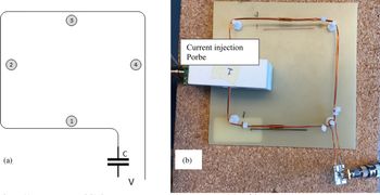
During the transmit phase of the MRI system, it is critical that the strong B 1 field does not induce any unwanted currents on the antennas. For the best performance, the location to place the floating filters needs to be determined. The current on each leg of the antenna can be calculated using an S21 measurement by driving the input port of the antenna using port 1 of the network analyzer and using a current probe around the antenna conductor connected to port 2 of the network analyzer. The test setup is shown in Fig. 14. The currents on each leg of the antenna are measured with and without floating filters, and the results are given in Table 1.
(a) WPT antenna and (b) the test setup to measure the current on each leg of the antenna.

Current measurements on each leg of the WPT antenna

From the test data collected above, the floating filters perform optimally when placed on legs 1 and 3 of the WPT antenna. Nevertheless, in general, the results show excellent performance, and using two filters provides better isolation from the MRI frequency than using a single filter.
6.1.2 Isolating MRI frequencies using floating filters
The test setup shown in Fig. 15(a) is used to measure the notch response of the two floating filters when attached to the WPT antenna. The first of the two probes wrapped around the antenna induces a current on the conductor, and the second probe is used to pick up the current induced.
(a) The setup to measure the performance of the filter circuit on the test bench and (b) graph showing the filter performance in suppressing MRI frequencies with one and two filters.

As shown in Fig. 15(b), without a filter, all the power induced on the WPT antenna by Port 1 of the network analyzer was transferred to Port 2. Applying a floating filter circuit resulted in a notch response centered around 128 MHz, blocking the high-frequency signal without affecting the low-frequency wireless power signal (6.78 MHz). A suppression of 13 dB was observed at the frequency of interest, and the addition of a second filter to the WPT antenna improved the suppression by 6 dB resulting in a total suppression of 19 dB.
6.1.3 Isolating WPT antennas and MRI receive coils
A two-channel phased array RF surface coil was constructed to study the effect of the WPT antenna on the RF surface coil's receiving performance. The bench test was performed by measuring the transmission (S21) measurement of the RF surface coil. One channel of the two-channel phased array was excited by injecting a signal at 128 MHz using a flux probe connected to Port 1 of a Keysight 5072A network analyzer while Port 2 of the analyzer was connected to the output of the LNA. The response of the RF surface coil under ideal conditions is shown in Fig. 16(b). The performance changed drastically when the WPT antenna was in proximity to the RF surface coil due to the effects of inductive and capacitive coupling with the RF surface coil (gray trace in Fig. 16(c)). As seen from the yellow and blue traces in Fig. 16(c) the addition of one and two floating filters respectively reduced the coupling and restored the performance of the RF surface coil at the MRI system's operating frequency.
The S21 performance of one of the channels from a two-channel phased array. (a) Experimental setup, (b) S21 performance without the WPT antenna in proximity, and (c) S21 performance of the phased array in the proximity of a WPT antenna with and without filters.

6.2 MRI system performance
6.2.1 B 1 distortion tests
The performance of the two TX WPT antennas during the transmit phase of the MRI system was evaluated by measuring the B 1 distortion profiles in a 3 T Philips Healthcare Ingenia MRI system. In [Reference Ganti, Lin, Wynn and Ortiz5], the distortion profiles of the antenna with and without the filter circuit were presented. The authors noted that with a filter circuit, the distortion on the surface of the phantom was reduced to 14% from the 32% distortion without the filter. The same tests were repeated, and the distortion profiles of the WPT antenna placed on a phantom without a filter, with one filter, and with two filters are shown in Figs 17(a), 17(b), and 17(c) respectively. A B 1 distortion of 27% was measured without any filter. The addition of a single floating filter reduces the distortion to 17%, and the addition of a second floating filter reduced the distortion further down to 11% on the surface of the phantom. The result obtained using one floating filter agrees with the previously published result, and the addition of the second floating filter further decreased the distortion by 35% as compared to the case with only one floating filter.
B 1 distortion profiles of the 2-turn antenna (a) without a filter, (b) with one filter, and (c) with two filters.

B 1 distortion reduces with distance, and a second set of tests to measure the depth of B 1 distortion within the phantom were performed with the same 2-turn WPT antenna as used for Fig. 17. To measure the depth of distortion, the second set of tests was performed in the phantom's and WPT antenna's transverse plane. A distortion of 25% was measured without any filters (Fig. 18(a)), and the distortion reduced to 9% (Fig. 18(b)) with the application of one floating filter. The addition of a second floating filter (Fig. 18(c)) almost eliminated any distortion resulting in a distortion of 2.3%, improving the performance by 74% as compared to the case with just one floating filter. This distortion is less than the target distortion of 5%. Also, the depth of distortion caused by the WPT antenna was reduced from 32 mm (without a filter) to <5 mm (with floating filters), as shown in Fig. 18(a) and 18(c). The addition of the second filter renders the WPT antenna almost entirely invisible to the MRI system.
B 1 distortion of the 2-turn antenna in the transversal plane (a) without filter, (b) with one filter, and (c) with two filters.

6.2.2 Measuring the effect of WPT antennas on the RF surface coils through SNR study
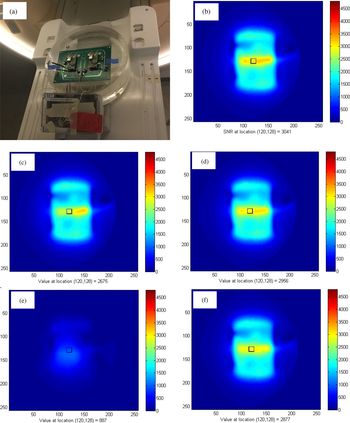
A spin-echo pulse sequence was utilized to obtain images for calculating the SNR of RF surface coils, and the results are shown in Fig. 19. To perform this measurement, the two-channel RF surface coil was placed on a phantom as shown in Fig. 19(a) and the WPT antenna were placed on the RF coil array to mimic a worst-case situation, as discussed above (Fig. 4). The raw data was collected after the completion of the scan and reconstructed in MATLAB using the sum of squares method described by Roemer et al., [Reference Roemer, Edelstein, Hayes, Souza and Mueller12].
SNR scans performed on a 2-channel phased array to show the effect of the power antennas on image quality (a) setup used to perform the measurement, (b) baseline SNR data without WPT antennas in proximity, (c) with 2-turn WPT antenna placed on the phased array, (d) 2-turn WPT antenna with two filters placed on the phased array, (e) 1-turn WPT without filter circuits placed on phased array, and (f) 1-turn WPT antenna with two filters placed on the phased array.

A voxel in the region of interest is used to measure the SNR. In this experiment, the location (120, 128) was chosen because it is at the center of the phantom underneath the WPT antenna. The receive coils have a high SNR, as seen in Fig. 19(b). The addition of the 2-turn WPT antenna reduced the SNR by 12%, and the application of two floating filters reduced the SNR by only 2.8%, improving the SNR by 70%. In the case of the 1-turn WPT antenna, the SNR loss exceeded 70% (Fig. 19(e)). This loss was unexpected, and upon further analysis, it was found that the 1-turn antenna was self-resonant, behaving like a short at 128 MHz, the operating frequency of the MRI system, and resulted in a catastrophic result. Even in this case, the application of the floating filters resulted in an SNR loss of only 5% and eliminated the adverse effects and distortions caused due to the unfiltered 1-turn antenna.
6.3 Wireless power transfer system efficiency
The system efficiency of the wireless power transmission was measured to check the effect of the filter on the transmit power antenna. The WPT power amplifier operates at 6.78 MHz and has a maximum output power of 35 W. A 50 Ω load was connected at the output of the WPT RX antenna. The system efficiency was measured by varying the distance between the WPT TX and WPT RX antennas with a step of 2.5 cm and plotted in Fig. 20. The maximum efficiency of 60% was measured when the distance between the TX and RX antennas was 2.5 cm. The addition of one filter circuit does not change the efficiency of the system, but the addition of the second filter slightly reduces the efficiency of the system. The efficiency was reduced due to the additional resistive losses introduced by the filter circuits in the WPT antenna and can be improved using the methods discussed above. The graph also shows the effect of the decreased mutual inductance with the 1-turn antenna. As seen from the figure, there is a 20% reduction in the efficiency of the system when the 1-turn antenna was used.
Comparing the power transfer efficiency of the WPT system with and without filters attached to the antennas.

7. Conclusion
In this paper, the authors demonstrated techniques to achieve the electromagnetic compatibility of the WPT antennas in the MRI system by adding floating filters. The addition of filters makes the WPT antennas electromagnetically compatible with the MRI system by reducing the high-frequency induced currents on the WPT antenna. The effectiveness of the floating filters in eliminating the induced currents during the transmit mode and reducing noise during the receive mode was supported by the test results on the bench and in the MRI scanner. An improvement in the reduction of B 1 distortion of greater than 50% was observed from the distortion profiles, and the desired B 1 distortion of less than 5% was achieved with the addition of the second filter. The measurement of the wireless power system efficiency shows that the addition of the filters does not cause a significant reduction of the power transfer efficiency. Higher power transfer efficiency with a higher mutual inductance was verified while maintaining electromagnetic compatibility. The maximum efficiency of 60% did not change with and without the filter circuit. The experiments show the effectiveness of the floating filter in isolating the high-frequency MRI signals from the low-frequency WPT signals in both MRI TX and RX modes without a significant change in the performance of either systems.
Appendix
Steps for performing B 1 on a Philips MRI system:
• Start the application software
• Place the object of interest on a phantom on the patient table and use the landmark button to place the object at the iso-center.
• In the Exam card tab first choose a Scout scan and perform the scan in all the scan planes.
• Choose the “Philips” tab in the exam card
• Double click on the “Applications” tab
• Double click on the “B 1 Map” tab
• Now, the number of slices can be chosen depending on the size of the object
• Hit start scan
• Once complete, right click on the image and click on draw a line profile
• Draw a line in the region of interest
• Right click on the line and click display line graph for the B 1 distortion graph
 Aasrith Ganti is pursuing his Ph.D. in electrical engineering from the University of Florida, Gainesville, FL, USA. He graduated with his B.S in Electronics and Communication Engineering from J.N.T University, Hyderabad in 2008 and Masters in Electrical Engineering from the University of Florida in 2012. He has been working as an Electrical Engineer for Philips Healthcare in the Research and Development group, Gainesville, FL. His research interests include Wireless Power, RF circuits, and systems as applied to medical devices particularly geared towards Magnetic Resonance Imaging. He received the 2018 IEEE Wireless Power Transfer Conference Best Student Paper Award.
 Jenshan Lin received the Ph.D. degree in electrical engineering from the University of California, Los Angeles, CA, USA, in 1994. He was with Lucent Bell Labs, Murray Hill, NJ, USA, from 1994 to 2001, and Agere Systems, Holmdel, NJ, USA, a spin-off company of Lucent Bell Labs, from 2001 to 2003. In 2003, he joined the University of Florida, Gainesville, FL, USA, where he is currently a Professor. Since October 2016, he has been on assignment to work for the U.S. National Science Foundation as a Program Director in Communications, Circuits, and Sensing Systems (CCSS) Program. He has authored or coauthored over 275 technical publications in refereed journals and conference proceedings. He holds 19 U.S. patents. His current research interests include sensors and biomedical applications of microwave and millimeter-wave technologies, wireless power transfer, and wireless communication systems.
Dr. Lin was a recipient of the 1994 UCLA Outstanding Ph.D. Award, the 1997 Eta Kappa Nu Outstanding Young Electrical Engineer Honorable Mention Award, the 2007 IEEE Microwave Theory and Techniques Society (MTT-S) N. Walter Cox Award, the 2015 IEEE Wireless Power Transfer Conference Best Paper Award, the 2016 Distinguished Alumnus Award from National Chiao Tung University, Hsinchu, Taiwan, and the 2016 IEEE RFIC Symposium Tina Quach Outstanding Service Award. He was the General Chair of the 2008 RFIC Symposium, the Technical Program Chair of the 2009 Radio and Wireless Symposium, and the General Co-Chair of the 2012 Asia-Pacific Microwave Conference. He served as the Editor-in-Chief of the IEEE TRANSACTIONS ON MICROWAVE THEORY AND TECHNIQUES in 2014–2016.
 Tracy A. Wynn received B.S. degrees in Electrical Engineering and Applied Mathematics in 1999 and an M.S. degree in Electrical Engineering in 2002 from Florida State University in Tallahassee, Florida. In 2010 he received his M.B.A. from the University of Florida in Gainesville, Florida. He joined MRI Devices in 2002 (later Philips/Invivo) in Gainesville, Florida as an RF engineer, designing MRI coils. He has worked on numerous research and commercial MRI coil products during his tenure, in various design and administrative capacities. He now serves as the Lead RF Architect for Patient Interface at Philips/Invivo.
 Timothy Ortiz received his B.S. and M.S. from the University of Florida, where his focus was on RF IC design. He joined Philips in April 2011 and is currently a Research Technologist. Current research topics include wireless medical transceiver and energy harvesting technology design. Before joining Philips, he worked for Motorola research and development on multiple wireless standard and technologies including BT, GPS, GSM, WCDMA, LTE, and 802.11x.