I. INTRODUCTION
Organic photovoltaic solar cells based on the so-called bulk-heterojunction (BHJ) concept are considered as promising cost-effective future energy source. The BHJ consists of an intermixed network of a conjugated polymer which serves as the electron donor and fullerene moiety as the electron acceptor. Improved material engineering and nanoscale morphology control led to the enhancements in solar cell efficiencies exceeding 12% today.1 However, despite their many advantages including low cost, flexibility, and light-weight, BHJ-based solar cells suffer from relatively fast degradation, which is hindering the large-scale economic exploitation of the technology. To prolong their lifetime, different encapsulation methods protecting the BHJ from humidity, oxygen, and UV radiation are usually applied, which further increase their price and complexity.Reference Jørgensen, Norrman, Gevorgyan, Tromholt, Andreasen and Krebs2 There is an ongoing discussion about the mechanisms causing the loss of efficiency in BHJ solar cells.Reference Jørgensen, Norrman, Gevorgyan, Tromholt, Andreasen and Krebs2 The degradation of electrode materials, interface layers like PEDOT:PSS or lithium fluoride, interfaces between the different layers comprising the solar cell and the degradation of the absorber material have been described.Reference Grancini, De Bastiani, Martino, Fazzi, Egelhaaf, Sauermann, Antognazza, Lanzani, Caironi and Franco3–Reference Street, Schoendorf, Roy and Lee6 While the degradation of electrodes and interfaces may be overcome by the proper selection of materials, the design of stable and efficient organic semiconductors for solar cells has been not straight forward. Especially the intrinsic photostability of these materials is still not very well understood.
In this work, we focus on the ability of BHJs comprising different polymer/fullerene blends to separate charges, which is a prerequisite for efficient free charge carrier generation.Reference Dyakonov, Zoriniants, Scharber, Brabec, Janssen, Hummelen and Sariciftci7 We investigate the influence of oxygen and light on the ability to separate charges in different semiconductor blends using electron spin resonance (ESR). ESR has also been applied to study the quality of organic semiconductors.Reference Susarova, Piven, Akkuratov, Frolova, Polinskaya, Ponomarenko, Babenko and Troshin8 We show that all investigated BHJs show excellent photostability upon long-term exposure to solar radiation when kept in vacuum. When oxygen is present, BHJs tend to degrade irreversibly in the presence of light. The rate of degradation depends on the polymer type and light intensity.Reference Sperlich, Kraus, Deibel, Blok, Schmidt and Dyakonov9,Reference Brabec, Gowrisanker, Halls, Laird, Jia and Williams10 We also explore the rise and decay kinetics of light-induced ESR signals to study the dynamics of the photoinduced charges. It was suggested earlier that monitoring the evolution of the resonance signal after switching off illumination allows for an estimation of the trap distribution in the sample.Reference Carati, Bonoldi and Po11–Reference Shames, Inasaridze, Akkuratov, Goryachev, Katz and Troshin13 Also the recombination mechanism of photoinduced charges was explored using light-induced electron spin resonance (LESR). At low temperatures, the observed kinetics were found to be based on nongeminate recombination of randomly distributed carriers with the recombination rate depending only on a tunneling process and therefore on the intrapair distance between the species.Reference Schultz, Scharber, Brabec and Sariciftci14 Investigating several different polymer–fullerene blends, we realized that due to the overlap of ESR signals related to the positive polaron on the polymer chain and the negative anion on the fullerene derivative, a detailed analysis of the decay kinetics can be very tricky. After resolving this issue (see the Supplementary Material), we found that the decay kinetics do not change upon long-term illumination. We also observed near-identical decay curves for all investigated blends suggesting that the same recombination processes are active in all studied semiconductors.
II. MATERIALS AND METHODS
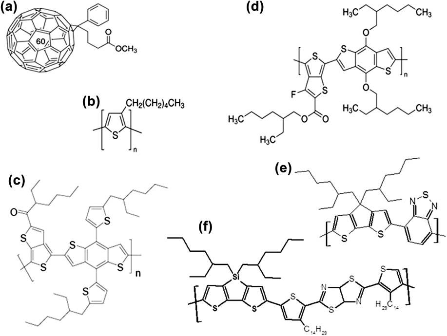
In this study, we use the ESR technique, which enables a contactless investigation of chemical and electronic processes in conjugated polymer/fullerene blends with sensitivity as low as 1011–1013 spins. All the measurements were carried out using a Bruker EMX X-band ESR (9.45 GHz) spectrometer (Bruker Corp., Karlsruhe, Germany) equipped with the Oxford ESR 900 Helium continuous flow cryostat (Oxford Instruments, Abingdon, United Kingdom) covering the temperature range from 4 to 300 K. ESR cavity operating in the TE102 mode with a 50% transparent window was used for all measurements. All ESR measurements were performed at the microwave power level of 200 μW (30 dB) and the external magnetic field was modulated with an amplitude of 1 G at 100 kHz. Sample illumination was carried out using a 20 W halogen lamp (Philips, Amsterdam, the Netherlands) placed about 30 cm away from the cavity. Long term illuminations were done using a solar simulator (Steurnagel), 100 mW/cm2 or UV-lamps, approximately 5 mW/cm2. All the samples were prepared in nitrogen-filled glove boxes to prevent any oxygen or water contamination. Oxygen and water concentration was kept below 1 ppm in either case. We prepared several series consisting of five samples with 1:1 weight ratio of polymer–fullerene mixtures in chlorobenzene. All solutions were prepared with a polymer concentration of 10 mg/mL. The following polymers were used as the electron donors: regio-regular poly(3-hexylthiophene-2,5-diyl) (P3HT)—Merck KGaA (Darmstadt, Germany), poly[2,6-bis(trimethyltin)-4,8-bis(5-(2-ethylhexyl)thiophen-2-yl)benzo[1,2-b:4,5-b′]dithiophene] (PBDTTT-C-T)—Solarmer (Irwindale, California), poly[4,8-bis[(2-ethylhexyl)oxy]benzo[1,2-b:4,5-b′]dithiophene-2,6-diyl][3-fluoro-2-[(2-ethylhexyl)carbonyl]thieno[3,4-b]thiophenediyl] (PTB7)—Solarmer (Irwindale, California), poly[(4,4′-bis(2-ethylhexyl)dithieno[3,2-b:2′,3′-d] silole)-2,6-diyl-alt-(2,5-bis 3-tetradecylth-iophen-2-yl-thiazolo-5,4-d-thiazole)-2,5diyl] (ZZ115)—Konarka GmbH (Nuremberg, Germany), and poly[2,1,3-benzothiadiazole-4,7-diyl[4,4-bis(2-ethylhexyl)-4H-cyclopenta[2,1-b:3,4-b′]dithiophene-2,6-diyl]] (ZZ50)—Konarka GmbH. As the electron acceptor, we chose a high-purity [6,6]-phenyl-C61-butyric acid methyl ester (PC60BM)—SolenneBV (Groningen, the Netherlands). Corresponding chemical structures are shown in Fig. 1.
(a) Phenyl-C61-butyric acid methyl ester (PCBM); (b) Poly(3-hexylthiophene-2,5-diyl) (P3HT); (c) Poly{[4,8-bis-(2-ethyl-hexyl-thiophene-5-yl)-benzo[1,2-b:4,5-b′]dithiophene-2,6-diyl]-alt-[2-(2′-ethyl-hexanoyl)-thieno[3,4-b]thiophen-4,6-diyl]} (PBDTTT-C-T); (d) Poly({4,8-bis[(2-ethylhexyl)oxy]benzo[1,2-b:4,5-b′]dithiophene-2,6-diyl}{3-fluoro-2-[(2-ethylhexyl)carbonyl]thieno[3,4-b]thiophenediyl}) (PTB7); (e) poly[(4,4′-bis(2-ethylhexyl)dithieno[3,2-b:2′,3′-d]silole)-2,6-diyl-alt-(2,1,3-benzothiadiazole)-4,7-diyl] (ZZ50 or PCPDTBT); (f) poly[(4,4′-bis(2-ethylhexyl)dithieno[3,2-b:2′,3′-d]silole)-2,6-diyl-alt-(2,5-bis-3-tetradecylthiophen-2-yl thiazolo 5,4-d thiazole)-2,5diyl] (ZZ115 or KP115).

Sample solutions were stirred at 80 °C for at least 24 h. In the next step, 0.3 mL of solution was dropped into a 4 mm o.d. ESR low pressure quartz tube (Wilmad-LabGlass). The tube was connected to a turbo pump and the solvent was carefully removed. The sample was subsequently annealed at 130 °C for 5 min, and the tube was sealed afterwards at a base pressure of approximately 10−4 mbar using a hydrogen flame. With this procedure, each ESR tube contained about 3 mg of polymer and 3 mg of fullerene material. The vacuum inside the tube was checked using a high frequency spark vacuum tester. The vacuum level was monitored throughout the entire investigation which turned out to be crucial for the success of the performed work. In a few samples, the repeated measurements at low temperatures induced microcracks in the sealed tubes leading to an uncontrolled ingress of ambient air. Monitoring the vacuum levels allowed for the rejection of unintentionally contaminated samples. For the investigation of the effect of oxygen on the sample degradation, low pressure ESR tubes (Wilmad-LabGlass) were used. The samples were prepared as described above. During the experiments, oxygen was injected into tubes in a home-build environmental chamber filled with technical grade oxygen, which was dried using a multistage KOH humidity filter. After oxygen injection, the tubes were closed with a gas-tight cap. All the experiments of the same type were carried out in parallel, i.e., all five blends were exposed to the same conditions and underwent the same treatment.
III. RESULTS AND DISCUSSION
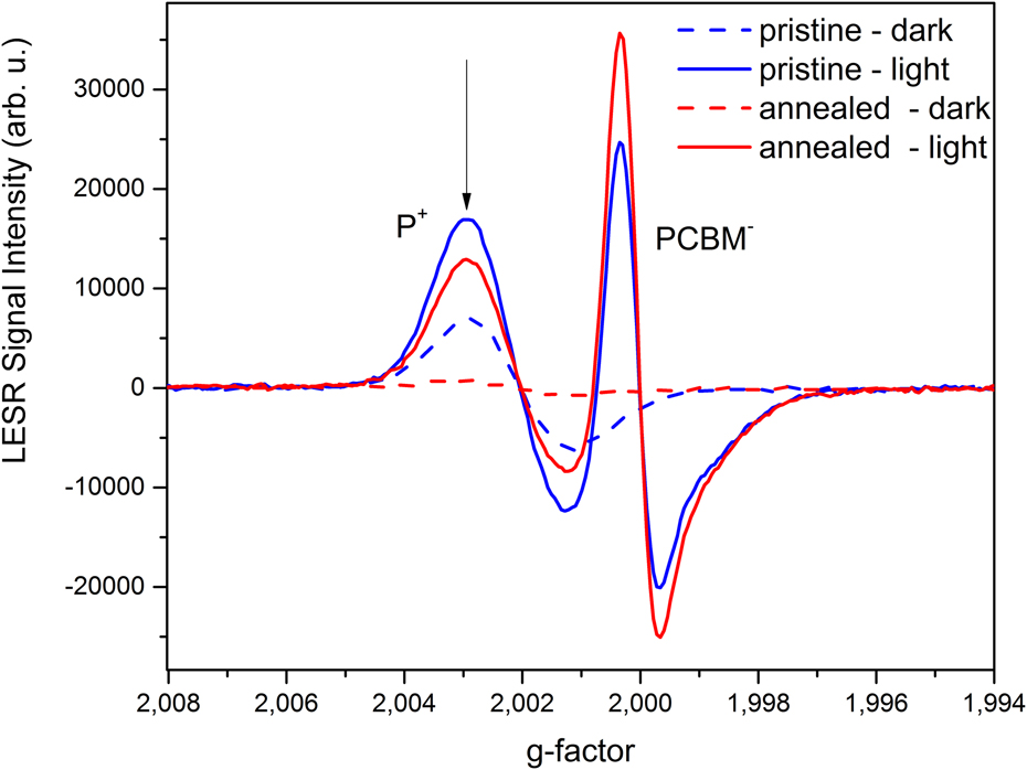
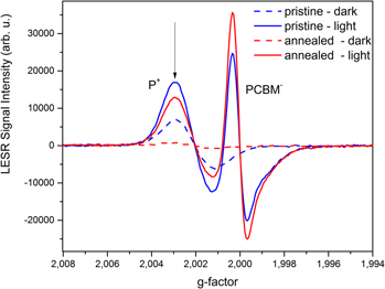
Figure 2 shows typical light-induced and dark ESR spectra of the polymer–fullerene blend based on P3HT and PCBM measured at 60 K. One sample was investigated as prepared while the second sample was annealed for 5 min at 400 K under vacuum. A clear separation of the polymer P+ and fullerene (PCBM−) peak in the pristine sample in the absence of oxygen is observed.Reference Dyakonov, Zoriniants, Scharber, Brabec, Janssen, Hummelen and Sariciftci7 The g-factor of fullerene anion is 1.9995. The g-factor of conjugated polymer radicals is larger than 2 and is typically between 2.0023 and 2.0040. Annealing the samples had a strong impact on the spectra recorded without illumination. Not annealed samples showed a pronounced dark signal with a g-value and a line-width similar to the positive polaron signal observed upon illumination. This finding supports the idea that oxygen is doping P3HT. Upon careful annealing, oxygen can be removed and the related ESR signal can be reduced significantly.
Examples of dark and LESR spectra of P3HT:PCBM in a vacuum sealed tube at 60 K in a pristine and annealed sample. The broader resonance is ascribed to positive polarons P+ on the polymer moiety and the narrower resonance is ascribed to electrons on the fullerene moiety. A halogen lamp was used as the light source for the LESR experiments.

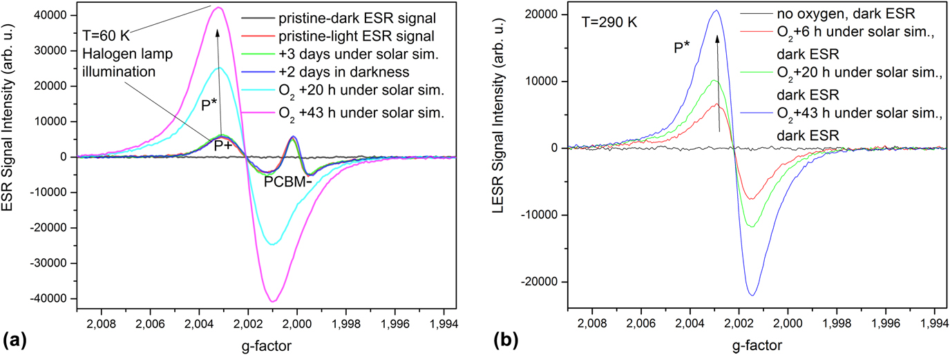
In Fig. 3(a), an example of ESR spectra of the ZZ115:PCBM blend measured at 60 K under halogen lamp illumination (LESR) is shown. Evacuated samples of all tested polymer/fullerene blends exposed to the simulated solar radiation (AM 1.5) for more than 100 h show no changes (within the experimental error) in dark and light-induced ESR spectra. A distinct charge separation is observed in all investigated blends. The situation changed dramatically when dry oxygen was injected into ESR tubes (1 bar), and the samples were exposed to simulated solar radiation or UV light for a longer time. In all semiconductor blends exposed to oxygen and solar radiation, the light-induced PCBM− peak gradually disappears [Fig. 3(a)] and a new polymer peak P* grows continuously. The g-factors of the P+ and P* peaks are very close to each other and cannot be easily distinguished by X-band (10 GHz) EPR.Reference Sperlich, Kraus, Deibel, Blok, Schmidt and Dyakonov9
Example of (L)ESR spectra of the ZZ115:PCBM in a flame-free Suprasil EPR low pressure tube before and after oxygen injection measured at (a) 60 K and (b) 290 K.
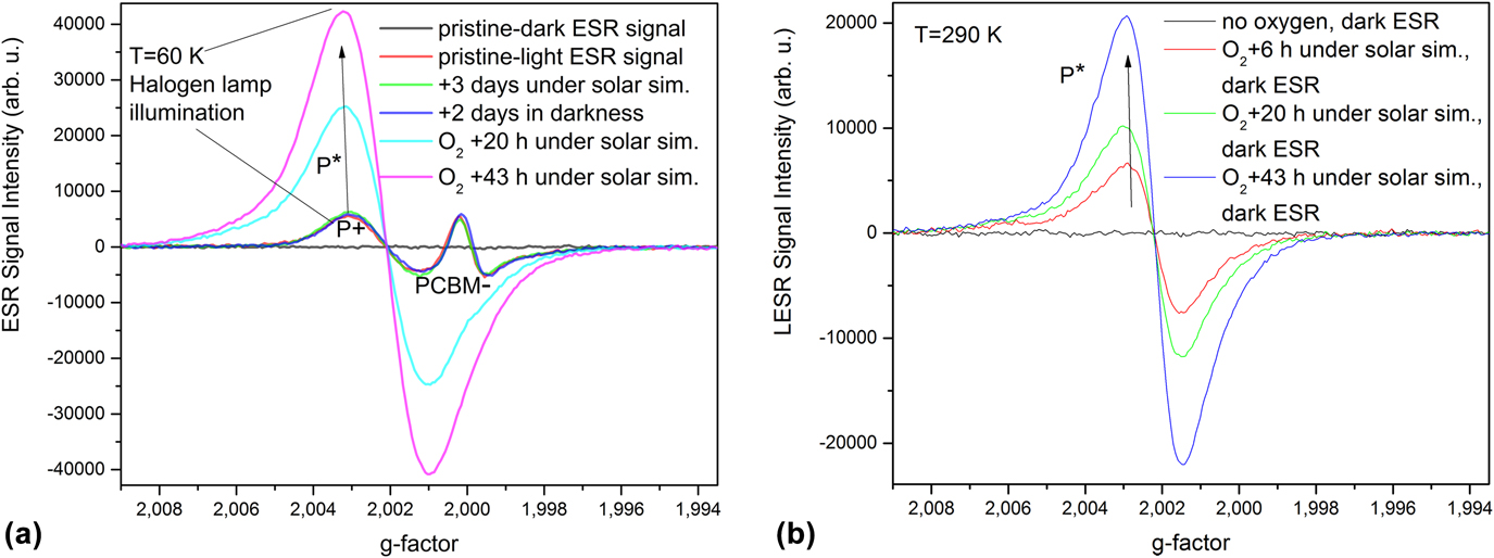
The growth of the P* peak is associated with photodegradation of the polymer moiety as described in Ref. Reference Sperlich, Kraus, Deibel, Blok, Schmidt and Dyakonov9. One part of the degradation process caused by the weak absorption of molecular oxygen to the polymer is to some extent reversible, and the initial polymer can be restored by simultaneous evacuation and annealing the sample at elevated temperature. After a few hours of light exposure in the presence of oxygen, the P* peak can no longer be removed by annealing. The signal is persistent and detectable even at room temperature. Long-term exposure to light and oxygen leads to the reduction of the P* signal. This suggests that further degradation leads to nonradical species of different polymer oxides PO2 which are ESR-silent.Reference Sperlich, Kraus, Deibel, Blok, Schmidt and Dyakonov9
The apparent relation between the loss of the charge separation ability in the BHJ and simultaneous growth of the P* peak is a powerful tool for the investigation of different degradation rates in conjugated polymer–fullerene blends. Following the development of P*, the photodegradation process and its kinetics in the presence of oxygen can be investigated by ESR even at room temperature. While the light-induced PCBM− and P+ signals disappear due to recombination, the signal related to P* is permanent. Therefore, monitoring the P* peak in dark and/or even at room temperature can give us an equivalent information about degradation kinetics of the polymer. If no degradation of the polymer takes place, no P* peak is observed in dark ESR. Following the evolution of P* may only deliver goods results at low and moderate degradation levels of the studied samples. As mentioned above, extensive degradation will lead to a reduction of the P*-concentration via the formation of ESR-silent polymer oxide. It should be pointed out that upon oxygen exposure, not only the PCBM− peak disappears but also its light-induced polymer counterpart P+ vanishes. The disappearance of the two light-induced ESR peaks does not mean a complete failure of the charge generation process. In our ESR experiments, only the steady-state concentration of all photogenerated charges, which is proportional to the number of photogenerated species N gen per second minus the number of recombining charges N rec per second, can be detected. A fast recombination induced by traps could lead to low steady-state concentration of photogenerated species. The total number of detectable species N ESR is exponentially dependent on temperature. This is one of the main reasons why low temperatures are necessary to detect light-induced ESR signals in BHJs. Another way of increasing the concentration of photoinduced spins is to increase the illumination light intensity which can be done using, e.g., a laser. However, this may cause some unwanted effects such as local heating, which is even more pronounced in evacuated EPR tubes where the heat exchange may be significantly hindered. It is therefore preferred to keep the excitation intensities at low levels. The relative number of degraded species can be evaluated directly from the signal amplitude of the P* peak. The ESR signal corresponds to the first derivative of the microwave absorption signal as the consequence of the magnetic field modulation. The relative number N of spin 1/2 species under the Lorentzian curve can be evaluated from the signal amplitude A and the signal linewidth w as N ∼ A × w 2. An alternative way to determine the relative number of spins is the signal double integration. This method is suitable for nonsymmetrical signals or for signals consisting of more lines with different g-factors as it is in our case due to g-factor anisotropy of the polymers.
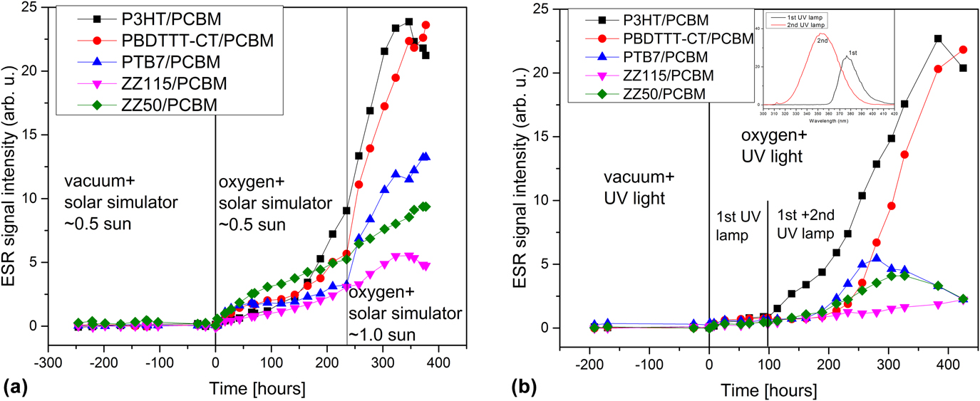
In Fig. 4(a), we show the results of double integration of P* peaks measured in the dark at room temperature for different blends before and after the exposure to dry oxygen and simulated AM 1.5 solar radiation. Without oxygen, no degradation occurs in any of the investigated blends.
(a) Double integrated dark ESR spectra (polymer P* peaks) of different polymer/fullerene blends. Samples were exposed to simulated solar radiation AM 1.5. (b) Double integrated dark ESR spectra (polymer P* peaks) of different polymer/fullerene blends. Samples were exposed to UV light. Inset: Emission spectra of both UV lamps used for sample degradation.
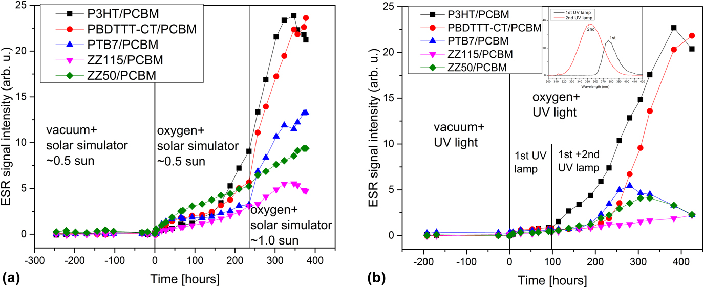
With oxygen, all blends show a gradual increase of the P* peak, which is associated with the loss of the ability to separate charges (PCBM− peak disappears). Different rates of degradation for different blends were observed. In the same figure, the dependence of the degradation rates on the light intensity is shown. While P3HT, PBDTTT-C-T, and PTB7 blended with PCBM show a strong intensity dependence, the degradation rate of ZZ50/PCBM and ZZ115/PCBM is almost constant when the samples are illuminated at 0.5 and 1 sun. Figure 4(b) shows the results of an equivalent degradation experiment where two laboratory UV lamps covering the range 325–400 nm were used instead of the simulated solar spectrum. First, the UV lamp with the peak wavelength of 380 nm and the light intensity of about 3 mW/cm2 was used to monitor the initial phase of the polymer degradation. Later, the second UV lamp with the peak wavelength of 350 nm and the light intensity of about 1 mW/cm2 was added, which resulted in an accelerated degradation of all polymers similar to the situation seen in the first case when the solar simulator with the light intensity of 1 sun was used. Our findings suggest that UV photons with higher energy create P*-species more effectively. This may partially be related to the stronger optical absorption of the organic semiconductor blends at shorter wavelengths. The number of photogenerated degradation products was estimated using the ESR strong pitch calibration sample. The maximum number of these products was of a similar order in all the samples and was found typically in the range of 1018–1019 per gram of the blend. Analyzing the data from Fig. 4 suggests that the P3HT/PCBM blend is the most sensitive and vulnerable to the presence of oxygen. We also see that PBDTTT-C-T and PTB7 show an intermediate degradation rate at lower light intensities, whereas they degrade faster at higher light intensities. ZZ115 and ZZ50 show only small sensitivity to increased light intensity. Preliminary device stability studies show that the degradation rates observed in the ESR experiments and stabilities of inverted state-of-the-art BHJ-devicesReference Udum, Denk, Adam, Apaydin, Nevosad, Teichert, White, Sariciftci and Scharber15 do not correlate very well.Reference Scharber16 Similar findings have been reported before.Reference Salvador, Gasparini, Perea, Harish Paleti, Distler, Inasaridze, Troshin, Lüer, Egelhaaf and Brabec17,Reference Razzell-Hollis, Wade, Chung Tsoi, Soon, Durrant and Kim18 This highlights the critical role of interlayers and electrodes and changes in the nanomorphology which is not detectable in our ESR studies. Crucial material parameters like charge carrier mobility may exhibit different dependencies on the degradation product densities in the studied semiconductor blends contributing to poor correlation between ESR and device stability in our experiments.
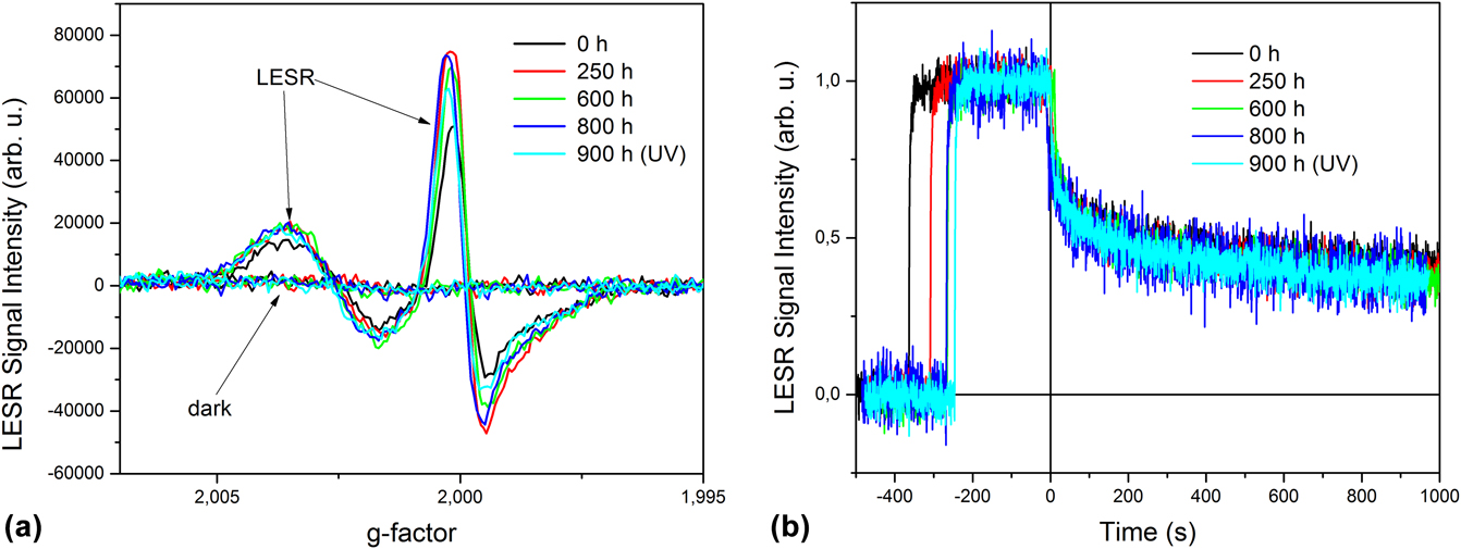
In Fig. 5, the ESR investigations on carefully sealed PTB7/PCBM samples and exposed to solar and UV radiation for several hundred hours are summarized. Without illumination no radicals are detected, while the typical light-induced positive polaron (P+) and the negative anion (PCBM−) are observed in the light-induced EPR experiment [Fig. 5(a)]. Throughout the experiment, the ESR spectra essentially remain unchanged. The small variations in the signal amplitudes are related to small variations of the sample position in the ESR cavity and the quality factor of the microwave system. Figure 5(b) shows the time evolution of the PCBM− signal under different illumination conditions. After recording the dark signal for a few minutes, the light is switched on and the ESR signal builds up quickly. The signal saturates quickly and the light-on signal is recorded for a few minutes before the light is switched off. The decay of the PCBM− signal consists of a fast component (prompt signal) and a long-lived component (persistent signal). The prompt signal originates from charge carriers which can recombine with nearby neighbors when the light excitation is switched off. During this process, the average distance between remaining charges increases and the recombination probability becomes smaller and smaller. At low temperatures, the mobility of charges is very low and they are mainly localized in shallow traps. It has been proposed that a tunneling process is dominating the long-lived component of the observed decay. Figure 5(b) shows the normalized spectra recorded on the same sample after different times of radiation exposure.
(a) LESR and (b) rise and decay curves of the PCBM− (L)ESR signal of PTB7:PCBM. The sample was measured at 60 K as prepared (t = 0 h), after 250 h, after 600 h, after 800 h under solar radiation and after additional 100 h UV exposure.
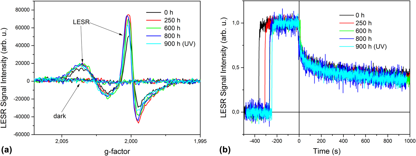
The observed spectra are essentially identical supporting the idea that no additional traps or defects effecting the charge generation and recombination are formed during long-term light exposure in the PTB7:PCBM blend when kept under inert conditions. Very similar results were found for the other polymer fullerene blends under investigation (see the Supplementary Material).
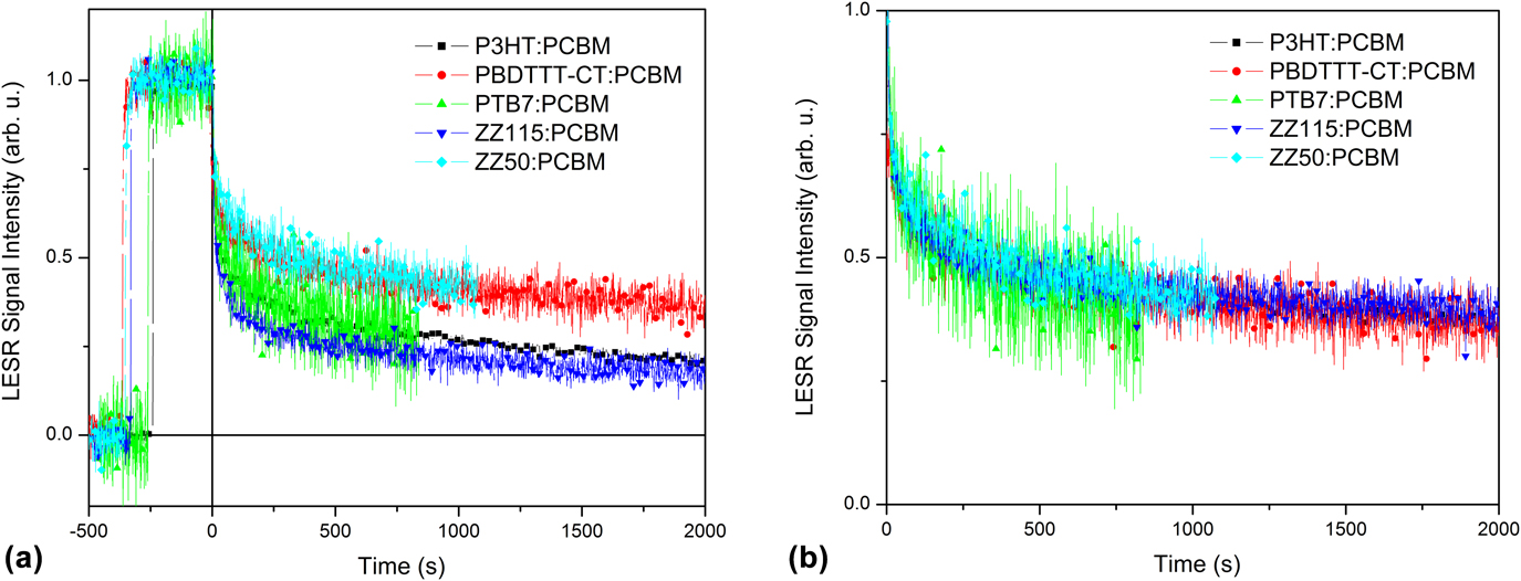
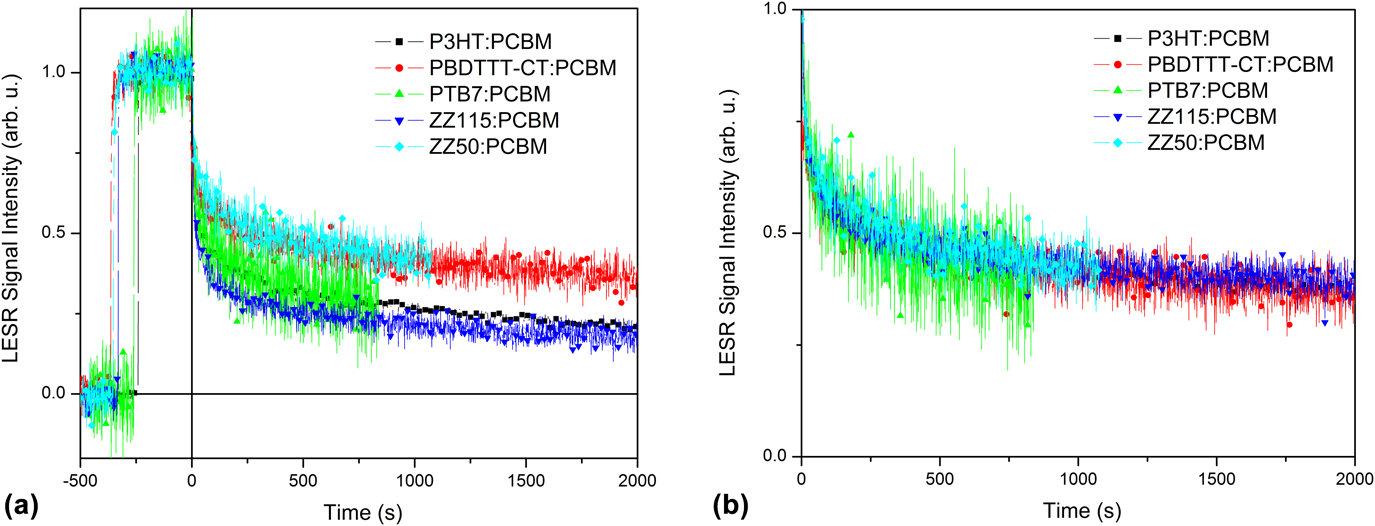
Comparing the low temperature decay of the different semiconductor blends, we find different amplitudes for the prompt component and the persistent components [Fig. 6(a)]. However, the persistent parts of the kinetics exhibit very similar kinetics suggesting that the same low temperature recombination processes are active in the semiconductor blends. A qualitative comparison of the decay curves is shown in Fig. 6(b). This is a very interesting finding. It supports the idea that the long-lived component of the recombination does not depend on the chemical structure of the organic semiconductors and the morphology of the polymer–fullerene blend. After the initial fast recombination, the distribution and energetics of charges is very similar leading to the same decay curves.
(a) Comparison of the rise and decay (L)ESR signal of PCBM− recorded for the different semiconductor blends measured after sample preparation at 60 K. (b) PCBM− decay curves shown in (a) with an additional offset to overlay the individual curves.
IV. SUMMARY
We have applied ESR to investigate photostability of different organic semiconductor blends. We find that in the absence of oxygen, the light-induced ESR spectra remain unchanged even after extensive exposure to solar or UV radiation. These results suggest that photogeneration and recombination of charges are highly reversible and that no spin-sensitive trap states or molecular defects are formed. In the presence of oxygen, exposure to solar or UV radiation leads to the formation of a stable radical species. At the same time, the ability to generate photoinduced charges is significantly reduced. The investigation of the recombination of photoinduced spins at low temperatures revealed that the kinetics of all polymer–fullerene blends are identical. This suggests that the same recombination mechanisms are active although the chemical structure of the semiconductors and the molecular arrangement of the donor and acceptor molecules are different in the investigated sample. The performed experiments prove that organic semiconductors exhibit excellent light stability under ideal conditions. The presented results suggest that a hermetic sealing of BHJ solar cells is mandatory to achieve long lifetime. In combination with durable electrode materials and optimized interfacial layers and interfaces, BHJ solar cells could achieve operational lifetime suitable for many relevant applications from powering sensors to large area power generation.
Supplementary Material
To view supplementary material for this article, please visit https://doi.org/10.1557/jmr.2018.210.
ACKNOWLEDGMENT
M.H. and M.C.S. acknowledge the FWF Austria Science Fund for financial support (FWF P25724-N19). N.S.S. acknowledges the FWF Austria Science Fund within the Wittgenstein Prize scheme (Z222-N19 Solare Energieumwandlung).