1 Introduction
The elastically mounted circular cylinder has been adopted as the canonical model for fundamental research on flow-induced vibration (FIV) of a bluff body in the past half-century, starting with the experiments on vortex-induced vibration (VIV) by Brooks (Reference Brooks1960) and numerous studies since (e.g. Feng Reference Feng1968; Khalak & Williamson Reference Khalak and Williamson1997; Govardhan & Williamson Reference Govardhan and Williamson2000; Zhao et al. Reference Zhao, Leontini, Lo Jacono and Sheridan2014a ). This is mainly attributed to its simplicity and axial symmetry, allowing VIV to be studied independently from other forms of FIV (e.g. galloping), and the importance of FIV of such structures in a large variety of engineering applications such as oil rig risers in ocean currents, high-rise buildings in winds and cooling arrays in nuclear power plants. However, when this symmetry is broken, structures (e.g. ice-coated transmission cables in winds, as reported by Den Hartog (Reference Den Hartog1932)) may be susceptible to another phenomenon typical of FIV, galloping, as opposed to, or in addition to, VIV. Galloping, associated with the asymmetric aerodynamic force arising from the body motion, is categorised as movement-induced excitation, whereas VIV, caused by the vortex shedding in the wake of a body, is categorised as instability-induced excitation (see Naudascher & Rockwell Reference Naudascher and Rockwell2005). These FIV phenomena can lead to undesired vibration, fatigue damage of structures or even structural failures; therefore, the subject of FIV of bluff bodies has motivated a large body of fundamental research work that aims to characterise, predict and control FIV, as collected in comprehensive reviews by Bearman (Reference Bearman1984), Sarpkaya (Reference Sarpkaya2004) and Williamson & Govardhan (Reference Williamson and Govardhan2004) and books by Blevins (Reference Blevins1990), Naudascher & Rockwell (Reference Naudascher and Rockwell2005) and Païdoussis, Price & De Langre (Reference Païdoussis, Price and De Langre2010), among others. Of interest to the current study is the symmetry breaking introduced by the body rotation of an elastically mounted circular cylinder undergoing in-line FIV.
Previous studies of transverse FIV of bluff bodies (e.g. Corless & Parkinson Reference Corless and Parkinson1988; Nemes et al.
Reference Nemes, Zhao, Lo Jacono and Sheridan2012; Zhao et al.
Reference Zhao, Leontini, Lo Jacono and Sheridan2014b
) have shown that VIV can still occur under certain conditions of flow velocity and structural properties (e.g. mass and damping ratios), and dominate over a range of reduced velocity when the axial symmetry of a body is broken. It should be noted that the reduced velocity is defined by
 $U^{\ast }=U/(\,f_{n}D)$
, where
 $U$
is the free-stream velocity,
 $f_{n}$
is the natural frequency of the system (in quiescent fluid) and
 $D$
is the cylinder diameter. In general, VIV is characterised by limited amplitude response (e.g. generally with the maximum amplitude of the order of one body diameter) and a lock-in region, where the body oscillation frequency matches that of the vortex shedding. Under broken symmetry, the galloping phenomenon may also be encountered, which is typically characterised by body oscillations with amplitudes increasing monotonically with the reduced velocity and frequencies much lower than that of vortex shedding (see Bearman et al.
Reference Bearman, Gartshore, Maull and Parkinson1987). Unlike VIV which involves a mechanism of lock-in, galloping is driven by the asymmetric aerodynamic force resulting from the asymmetric pressure distribution around the body that is created by the instantaneous body orientation and the relative oncoming flow. However, depending on the flow velocity and structural properties, the two phenomena of FIV may occur simultaneously, resulting in strong fluid–structure interaction, as demonstrated by Nemes et al. (Reference Nemes, Zhao, Lo Jacono and Sheridan2012) and Zhao et al. (Reference Zhao, Leontini, Lo Jacono and Sheridan2014b
).
In the present study, while the axial symmetry of the body geometry is preserved, an axial asymmetry of the fluid–structure system is introduced by applying forced body rotation to an elastically mounted circular cylinder. The case of a rigidly mounted (non-oscillating) circular cylinder rotating about its axis in a uniform flow has been extensively investigated over the past century (e.g. Reid Reference Reid1924; Swanson Reference Swanson1961; Mittal & Kumar Reference Mittal and Kumar2003; Radi et al.
Reference Radi, Thompson, Rao, Hourigan and Sheridan2013), to examine the effects of the imposed rotation on the wake structure and fluid forces, i.e. lift augmentation due to the Magnus effect (see Seifert Reference Seifert2012). It has been found in these previous studies that the fluid forces and the wake patterns are dependent on both the Reynolds number
 $(Re)$
and the non-dimensional rotation rate of the cylinder
 $(\unicode[STIX]{x1D6FC})$
. The Reynolds number is defined by
 $Re=UD/\unicode[STIX]{x1D708}$
, where
 $\unicode[STIX]{x1D708}$
is the kinematic viscosity of the fluid; the rotation rate is defined as the ratio between the cylinder surface tangential velocity (
 $|\unicode[STIX]{x1D6FA}|D/2$
, with
 $\unicode[STIX]{x1D6FA}$
the angular velocity) and the free-stream velocity
 $(U)$
, namely
 $\unicode[STIX]{x1D6FC}=|\unicode[STIX]{x1D6FA}|D/(2U)$
. In particular, asymmetric alternating Bénard–von-Kármán (BvK) vortex shedding (also known as mode-I shedding) occurs for low rotation rates
 $0<\unicode[STIX]{x1D6FC}\lesssim 2$
over a wide range of Reynolds number (see Coutanceau & Ménard Reference Coutanceau and Ménard1985; Badr et al.
Reference Badr, Coutanceau, Dennis and Menard1990; Rao et al.
Reference Rao, Leontini, Thompson and Hourigan2013). While the BvK vortex shedding is suppressed for higher rotation rates
 $\unicode[STIX]{x1D6FC}\gtrsim 2$
, there exists a secondary regime (also known as mode-II shedding) of the unsteady wake over a narrow range of
 $4.3\lesssim \unicode[STIX]{x1D6FC}\lesssim 5.6$
(see Stojković, Breuer & Durst Reference Stojković, Breuer and Durst2002; Kumar, Cantu & Gonzalez Reference Kumar, Cantu and Gonzalez2011). In this regime, single-sided vortex shedding occurs, with the shedding frequency much lower than that of two-sided BvK vortex shedding at lower rotation rates. In fact, there exist a number of regimes of steady and unsteady flow structures in the
 $Re{-}\unicode[STIX]{x1D6FC}$
parameter space (Pralits, Giannetti & Brandt Reference Pralits, Giannetti and Brandt2013; Rao et al.
Reference Rao, Leontini, Thompson and Hourigan2013, Reference Rao, Radi, Leontini, Thompson, Sheridan and Hourigan2015).
Despite a significant amount of research on the rigidly mounted cylinder case, very few studies have been conducted to examine the impact of body rotation on FIV of an elastically mounted cylinder. Bourguet & Lo Jacono (Reference Bourguet and Lo Jacono2014) were the first to report a numerical study of the transverse FIV of a rotating cylinder at low Reynolds number. The numerical simulations in this study were performed at
 $Re=100$
over a parameter space spanning the reduced velocity range
 $4\leqslant U^{\ast }\leqslant 34$
and the rotation rate range
 $0\leqslant \unicode[STIX]{x1D6FC}\leqslant 4$
. They found that the magnitude of the time-averaged displacement of the cylinder tended to increase monotonically with the rotation rate, as did the time-averaged transverse lift force coefficient. Overall, they identified three response regimes of the fluid–structure system in the
 $U^{\ast }{-}\unicode[STIX]{x1D6FC}$
parameter space: the vibration region, the steady flow regime and the unsteady flow regime. In the steady and unsteady flow regimes, the oscillation amplitudes were observed to be extremely low (less than
 $0.05D$
). Over the entire vibration region, the structural response and the wake dynamics appeared to be synchronised, which was similar to the lock-in behaviour in VIV of the non-rotating case. Associated with such wake–body synchronisation, large oscillations were encountered, and the amplitude response was found to increase with the rotation rate for
 $\unicode[STIX]{x1D6FC}\leqslant 3.75$
. The peak of the normalised amplitude (
 $A^{\ast }=A/D$
, with
 $A$
the oscillation amplitude) response observed was close to
 $A^{\ast }=1.9$
at
 $(\unicode[STIX]{x1D6FC},U^{\ast })=(3.75,13)$
, three times the peak response of the non-rotating case. Meanwhile, in addition to the wake patterns (i.e. 2S, P+S) that have commonly been seen in previous studies of VIV of a non-rotating cylinder (e.g. Williamson & Roshko Reference Williamson and Roshko1988; Jauvtis & Williamson Reference Jauvtis and Williamson2004), they also identified a novel asymmetric wake pattern composed of a triplet of vortices and a single vortex shed per cycle, referred to as the T+S pattern, which was attributed to the largest-amplitude response and moderate to low oscillation frequencies.
More recently, Wong et al. (Reference Wong, Zhao, Lo Jacono, Thompson and Sheridan2017) conducted extensive experiments to characterise the dynamic response and wake structures of a rotating cylinder undergoing transverse FIV over the Reynolds number range
 $1100\lesssim Re\lesssim 6300$
. They observed significant structural oscillations associated with wake–body synchronisation for rotation rates up to
 $\unicode[STIX]{x1D6FC}\approx 3.5$
. The amplitude response was reported in a statistical form of
 $A_{10}^{\ast }$
denoting the mean of the highest 10 % of normalised amplitude response peaks about their time-averaged positions, as in previous studies by Nemes et al. (Reference Nemes, Zhao, Lo Jacono and Sheridan2012) and Zhao et al. (Reference Zhao, Leontini, Lo Jacono and Sheridan2014b
). It was found to increase with the rotation rate for
 $\unicode[STIX]{x1D6FC}\leqslant 2.0$
, prior to a decreasing trend for higher
 $\unicode[STIX]{x1D6FC}$
values. The peak amplitude response was observed to be
 $A_{10}^{\ast }\approx 1.4$
at
 $(\unicode[STIX]{x1D6FC},U^{\ast })=(2.0,6.0)$
, a 76 % increase over the non-rotating case. Moreover, overlaid on a contour map of the amplitude response in the
 $U^{\ast }{-}\unicode[STIX]{x1D6FC}$
parameter space, a variety of wake patterns and switching behaviours were observed.
Compared with transverse-only VIV of a non-rotating circular cylinder, only limited attention has been given to the case of one-degree-of-freedom (1-DOF) in-line VIV, mainly due to the fact that in-line vibration amplitudes are much lower (
 $A^{\ast }\lesssim 0.1$
) and perhaps less significant than the transverse-only VIV case (Leontini, Lo Jacono & Thompson Reference Leontini, Lo Jacono and Thompson2011; Cagney & Balabani Reference Cagney and Balabani2013a
, Reference Cagney and Balabani2014; Konstantinidis Reference Konstantinidis2014). However, the earlier numerical study of Bourguet & Lo Jacono (Reference Bourguet and Lo Jacono2015) concerning 1-DOF in-line FIV of a rotating cylinder, again at a low Reynolds number
 $Re=100$
, showed that imposed body rotation could lead to large-amplitude oscillations. Overall, they identified two structural vibration regions and one steady flow region in the
 $U^{\ast }{-}\unicode[STIX]{x1D6FC}$
parameter space of
 $1\leqslant U^{\ast }\leqslant 23$
and
 $0\leqslant \unicode[STIX]{x1D6FC}\leqslant 3.5$
. The first vibration region was encountered for
 $0\leqslant \unicode[STIX]{x1D6FC}\lesssim 1.8$
, where the system exhibited VIV synchronisation responses with the peak vibration amplitudes observed around
 $U^{\ast }=6$
. The maximum peak vibration amplitude in this region was observed to be
 $0.06D$
for
 $\unicode[STIX]{x1D6FC}=1.5$
. Similarly to the case of transverse VIV of a non-rotating cylinder, a wake–body synchronisation or lock-in region was also identified. Correspondingly, a 2S mode was found to be associated with the wake–body synchronisation. The second vibration region was characterised as a ‘galloping-like’ region, occurring for
 $\unicode[STIX]{x1D6FC}\geqslant 2.65$
and
 $U^{\ast }\gtrsim 8$
. In this region, the cylinder oscillations resembled the transverse galloping responses of non-axisymmetric bodies, where the amplitude response tended to increase with
 $U^{\ast }$
without bound, e.g. to an amplitude response greater than
 $2.5D$
for
 $(\unicode[STIX]{x1D6FC},U^{\ast })=(3.5,23)$
. The amplitude response was also found to increase with
 $\unicode[STIX]{x1D6FC}$
for a given
 $U^{\ast }$
. Correspondingly, the low-frequency and large-amplitude responses were found to be associated with novel asymmetric wake patterns, consisting of a pair and a triplet or a quartet of vortices shed per cycle. In the steady flow region, which lies between these two vibration regions in the
 $U^{\ast }{-}\unicode[STIX]{x1D6FC}$
parameter space, the flow remained steady and no structural vibration was observed.
In summary, previous numerical studies have investigated the FIV responses and wake patterns for both the 1-DOF transverse and in-line cases, but only at low Reynolds numbers. While in agreement with the previous low-
 $Re$
studies that body rotation can both significantly enhance and suppress vibration amplitudes, the higher-Reynoldsnumber experimental study of Wong et al. (Reference Wong, Zhao, Lo Jacono, Thompson and Sheridan2017) has shown that the transverse case exhibits significantly different behaviour in terms of the wake–body synchronisation region with rotation rate, peak amplitude response and the wake patterns. These differences may arise from the difference between two- and three-dimensional flows. Moreover, given the different fluid–structure interaction mechanisms between the in-line and transverse cases as observed in two-dimensional simulations, it is therefore useful to experimentally verify the in-line case, again at a Reynolds number that is likely to be more relevant to typical applications.
Definition sketch for in-line flow-induced vibration of a rotating cylinder. The hydroelastic system is simplified as a 1-DOF system constrained to move in the streamwise direction. The axis of rotation is perpendicular to the
 $x$
–
 $y$
plane. Here,
 $U$
is the free-stream velocity,
 $D$
is the cylinder diameter,
 $m$
is the oscillating mass,
 $k$
is the spring constant,
 $c$
is the structural damping and
 $\unicode[STIX]{x1D6FA}$
is the angular velocity;
 $F_{x}$
and
 $F_{y}$
represent the streamwise (drag) and transverse (lift) force components acting on the body, respectively.

In terms of why control using rotational oscillation is interesting in general, the effect of cylinder rotation on the flow past a cylinder is twofold. Increase in rotation increasingly breaks the rotational symmetry of the set-up, so that while a non-rotating circular cylinder is not subject to galloping, the addition of rotation enables this FIV mechanism to operate. Thus, in a sense, the addition of rotation can be considered to have an analogy to distorting the body shape and correlating the effect on the FIV response. In addition, rotation breaks the symmetry of the upper and lower vortex streets in the wake, and beyond a certain rotation rate produces a one-sided vortex street wake or prevents vortex shedding at all. In a sense, this has analogies with flows past airfoils, which effectively generate lift through so-called ‘bound’ circulation.
The present paper aims to explore the in-line FIV response of a rotating cylinder at moderate Reynolds number to gain a deeper understanding of the vibration response regimes and fluid–structure interaction mechanisms. More specifically, this investigation experimentally characterises the structural vibration response, fluid forces and wake patterns over a large
 $U^{\ast }{-}\unicode[STIX]{x1D6FC}$
parameter space and a high
 $Re$
range, where the flow is presumably three-dimensional.
The study proceeds by describing the fluid–structure system modelling and the experimental details in § 2. The results and discussion, including the structural response, analyses of fluid forcing and phasing, and wake patterns, are presented in § 3. Finally, conclusions are drawn in § 4.
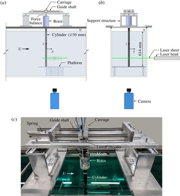
Schematics of the experimental set-up are shown in (a) side view and (b) back view. A photograph of the rig placed on top of the water channel is shown in (c).

2 Experimental method
2.1 Fluid–structure system modelling
A schematic of 1-DOF in-line FIV of a rotating cylinder is shown in figure 1, which defines key parameters of the system. The elastically mounted cylinder is free to oscillate in only one direction in line with the oncoming free stream. The body dynamics is governed by the linear second-order oscillator equation,
 $$\begin{eqnarray}m\ddot{x}(t)+c{\dot{x}}(t)+kx(t)=F_{x}(t),\end{eqnarray}$$
where
 $m$
is the total oscillating mass of the system,
 $c$
is the structural damping of the system,
 $k$
is the spring constant,
 $x(t)$
is the body displacement and
 $F_{x}(t)$
represents the streamwise fluid force. It should be noted that the streamwise and transverse fluid force coefficients used in this study are defined by
 $C_{x}=F_{x}/(\unicode[STIX]{x1D70C}U^{2}DL/2)$
and
 $C_{y}=F_{y}/(\unicode[STIX]{x1D70C}U^{2}DL/2)$
, respectively, where
 $\unicode[STIX]{x1D70C}$
is the fluid density and
 $L$
is the cylinder immersed span.
In the present study, the fluid–structure system was modelled based on a low-friction air-bearing system in conjunction with a recirculating free-surface water channel of the Fluids Laboratory for Aeronautical and Industrial Research (FLAIR) at Monash University. The test section of the water channel has dimensions of 600 mm in width, 800 mm in depth and 4000 mm in length. The free-stream velocity in the present experiments could be varied continuously over the range
 $50\leqslant U\leqslant 450~\text{mm}~\text{s}^{-1}$
. The free-stream turbulence level was less than 1 %. More details on this water-channel facility can be found in Nemes et al. (Reference Nemes, Zhao, Lo Jacono and Sheridan2012) and Zhao et al. (Reference Zhao, Leontini, Lo Jacono and Sheridan2014a
,Reference Zhao, Leontini, Lo Jacono and Sheridan
b
). Figure 2 shows a schematic of the present experimental set-up and a photograph of the rig to clarify details. The air-bearing system was supported atop and in line to the water channel. One pair of air bearings (model S302502; New Way Air Bearings, USA) was installed inside a slider carriage that was guided by precision stainless steel shafts to provide linear movement. The structural stiffness of the oscillating system was controlled by precision extension springs.
The rigid precision-made cylinder model used had an outer diameter of
 $D=30\pm 0.01~\text{mm}$
. The immersed length of the cylinder was
 $L=614~\text{mm}$
, giving an aspect ratio of
 $\def\AR{A\mkern-8muR}\AR =L/D=20.5$
. To reduce end effects of the cylinder and to promote parallel vortex shedding, an end conditioning platform was used. This platform had a stand height of 165 mm and a top plate with dimensions of 600 mm in width
 $\times$
500 mm in length
 $\times$
6 mm in thickness featured with a 1 : 4 semi-elliptical leading edge to avoid flow separation. A gap between the cylinder free end and the platform surface was set at approximately 1 mm (
 $3.3\,\%D$
).
The total oscillating mass of the system was
 $m=2479~\text{g}$
and the displaced mass of water was
 $m_{d}=\unicode[STIX]{x1D70C}\unicode[STIX]{x03C0}D^{2}L/4=433~\text{g}$
, giving a mass ratio of
 $m^{\ast }=m/m_{d}=5.73$
. By conducting free-decay tests individually in air and in quiescent water, the natural frequencies of the system in air and quiescent water were measured to be
 $f_{na}=0.333~\text{Hz}$
and
 $f_{nw}=0.307~\text{Hz}$
, respectively. Thus, the added mass, given by
 $m_{A}=((\,f_{na}/f_{nw})^{2}-1)m$
, was found to be 438 g, and the added mass coefficient, defined by
 $C_{A}=m_{A}/m_{d}$
, was found to be 1.01. The structural damping ratio with consideration of the added mass was found to be
 $\unicode[STIX]{x1D701}=c/2\sqrt{k(m+m_{A})}=2.44\times 10^{-3}$
, with
 $c\simeq 0.0274~\text{N}~\text{sm}^{-1}$
and
 $k\simeq 10.83~\text{N}~\text{m}^{-1}$
.
The cylinder rotation was driven by a rotor mechanism consisting of a pair of precision ball bearings and a miniature stepper motor (model LV172; Parker Hannifin, USA) that was controlled by a micro-stepping drive (model E-DC) with a resolution of 25 000 steps per revolution and a Parker 6K2 motion controller. The rotor mechanism was mounted vertically to a force balance coupled with the slider carriage.
2.2 Data acquisition and processing methods
The data acquisition (DAQ) and the control of the free-stream velocity and motor rotation speed over the
 $U^{\ast }{-}\unicode[STIX]{x1D6FC}$
parameter space were automated using a workstation computer equipped with customised LabVIEW (National Instruments, USA) programs. The reduced velocity was varied over the range of
 $5\leqslant U^{\ast }\leqslant 32$
in increments between 0.1 and 0.5 (depending on structural response regimes). The Reynolds number range was
 $1349\leqslant Re\leqslant 8624$
.
The body displacement was measured using a non-contact digital optical linear encoder (model RGH24; Renishaw, UK). This linear encoder had a resolution of
 $1~\unicode[STIX]{x03BC}\text{m}$
and a linear range of
 $\pm 200~\text{mm}$
available. An optical rotary encoder with a resolution of 4000 counts per revolution (model E5-1000; US Digital, USA) was used to measure the rotation speed.
The in-line fluid force (
 $F_{x}$
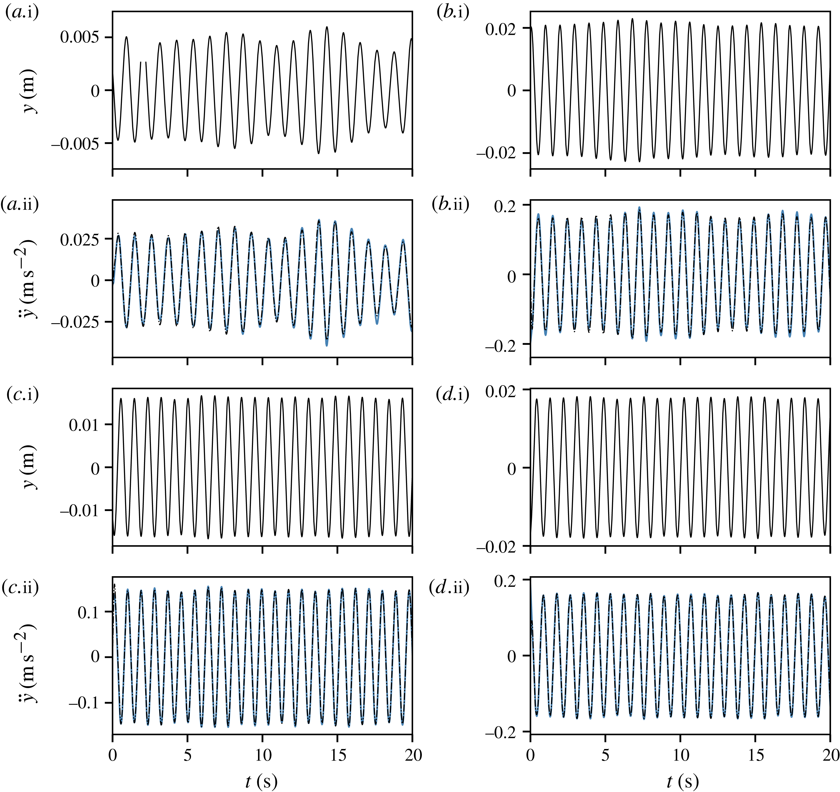
) acting on the vibrating cylinder was determined based on (2.1). On this point, in order to validate the body acceleration derived from the digital linear encoder signals, comparison measurements of the transverse VIV of a non-rotating cylinder were conducted against a high-sensitivity MEMS (micro-electro-mechanical system) accelerometer (model 3741E122G; PCB, USA). Validation test samples are provided in the Appendix. However, the measurement signals of the accelerometer in rotating cases could be severely affected by electromagnetic noise emitted from the driving motor. Thus, a technique based on accurately derived body velocity and acceleration was employed to determine
 $F_{x}$
, since the linear encoder signal was digital and its measurement accuracy was not affected by electromagnetic noise. The method and approach have been detailed and validated in Zhao et al. (Reference Zhao, Leontini, Lo Jacono and Sheridan2014b
). On the other hand, the transverse lift (
 $F_{y}$
) was measured by employing a force balance based on semiconductor strain gauges (see Zhao et al.
Reference Zhao, Leontini, Lo Jacono and Sheridan2014a
,Reference Zhao, Leontini, Lo Jacono and Sheridan
b
).
The flow structures in the near wake of the cylinder were measured using the particle image velocimetry (PIV) technique. The flow was seeded with hollow micro-spheres (model Sphericel 110P8; Potters Industries Inc.) having a normal diameter of
 $13~\unicode[STIX]{x03BC}\text{m}$
and a specific weight of
 $1.1~\text{g}~\text{m}^{-3}$
. Illumination was provided by two miniature Ng:YAG pulse lasers (model Minilite II Q-Switched; Continuum Lasers, USA) that produced a 3 mm thick horizontal planar sheet. Imaging was performed using a high-speed camera (model Dimax S4; PCO AG, Germany) with a resolution of
 $2016~\text{pixel}\times 2016~\text{pixel}$
. The camera was equipped with a 50 mm lens (Nikon Corporation, Japan), giving a magnification of approximately 9.73 pixel per mm for the field of view of interest. The PIV images pairs were sampled at 10 Hz. For each PIV measurement case in the
 $U^{\ast }{-}\unicode[STIX]{x1D6FC}$
space, a set of 3100 image pairs was recorded for analysis. To provide an insight into the evolution of the wake structures, which could be perturbed quickly by the cylinder rotation, images of each set were sorted into 48 phases based on the instantaneous phase angle between the cylinder displacement and velocity, yielding at least 60 image pairs for averaging. The PIV data were processed using validated in-house software developed by Fouras, Lo Jacono & Hourigan (Reference Fouras, Lo Jacono and Hourigan2008) using
 $32~\text{pixel}\times 32~\text{pixel}$
interrogation windows in a grid layout with 50 % window overlap.
2.3 Experimental validation
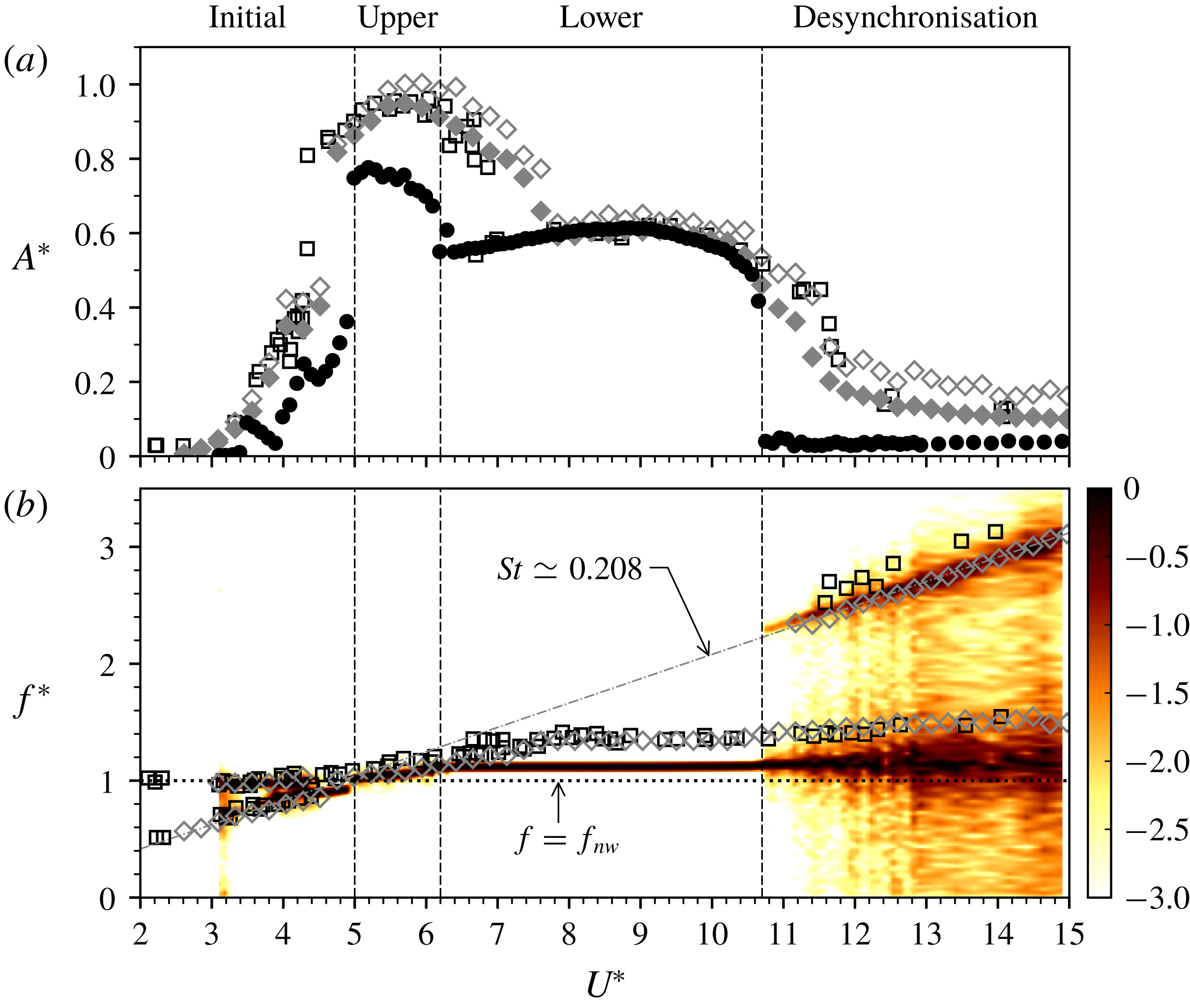
Structural vibration of non-rotating cylinders undergoing VIV. (a) The normalised amplitude response as a function of the reduced velocity. The solid circles (●) represent the mean of the highest 10 % of the amplitudes (
 $A_{10}^{\ast }$
) at each
 $U^{\ast }$
in the present study, with
 $m^{\ast }=5.73$
and
 $\unicode[STIX]{x1D701}=2.44\times 10^{-3}$
; the open diamonds (♢) and solid diamonds (♦) represent the
 $A_{max}^{\ast }$
and
 $A_{10}^{\ast }$
values, respectively, in Zhao et al. (Reference Zhao, Leontini, Lo Jacono and Sheridan2014b
), with
 $m^{\ast }=2.40$
and
 $\unicode[STIX]{x1D701}=2.43\times 10^{-3}$
; the open squares (▫) represent the
 $A_{max}^{\ast }$
values in Khalak & Williamson (Reference Khalak and Williamson1997), with
 $m^{\ast }=2.4$
and
 $\unicode[STIX]{x1D701}=4.5\times 10^{-3}$
. (b) The corresponding frequency responses of the previous studies overlapped on the logarithmic-scale power spectral density contour of the present study. It should be noted that the power spectral density is normalised by the maximum value at each
 $U^{\ast }$
.

The experimental methodologies have been validated in previous related studies (e.g. Nemes et al.
Reference Nemes, Zhao, Lo Jacono and Sheridan2012; Zhao et al.
Reference Zhao, Leontini, Lo Jacono and Sheridan2014a
,Reference Zhao, Leontini, Lo Jacono and Sheridan
b
; Wong et al.
Reference Wong, Zhao, Lo Jacono, Thompson and Sheridan2017; Sareen et al.
Reference Sareen, Zhao, Lo Jacono, Sheridan, Hourigan and Thompson2018). To provide a brief validation, a study of transverse VIV of a non-rotating cylinder was conducted to compare with previous work by Khalak & Williamson (Reference Khalak and Williamson1997) and Zhao et al. (Reference Zhao, Leontini, Lo Jacono and Sheridan2014b
). The comparison of the amplitude and frequency responses as a function of reduced velocity in figure 3 shows that in general the present results agree very well with the previous studies. It should be noted that
 $A_{max}^{\ast }$
in these two previous studies represents the maximum amplitude at each
 $U^{\ast }$
. In figure 3(a), the typical three amplitude response branches, consisting of the initial, upper and lower branches named by Khalak & Williamson (Reference Khalak and Williamson1996), are seen in the present results. The initial branch occurs for
 $U^{\ast }\leqslant 4.9$
; the upper branch exists for the range
 $5\leqslant U^{\ast }\leqslant 6.2$
; the lower branch covers the range
 $6.2<U^{\ast }\leqslant 10.7$
; the desynchronisation region appears for
 $U^{\ast }>10.7$
. Compared with the peak amplitude responses of the previous studies with lower mass ratio (
 $m^{\ast }=2.4$
), where
 $A_{max}^{\ast }\approx 0.95$
in Khalak & Williamson (Reference Khalak and Williamson1997) and
 $A_{max}^{\ast }\approx 1.0$
and
 $A_{10}^{\ast }\approx 0.95$
in Zhao et al. (Reference Zhao, Leontini, Lo Jacono and Sheridan2014b
), the current system sees a peak of
 $A_{10}^{\ast }\approx 0.8$
. In the lower branch, where the cylinder oscillations are highly periodic, the amplitude response remains fairly stable at
 $A_{10}^{\ast }\approx 0.6$
, consistent with the previous studies.
Figure 3(b) shows a power spectral density (PSD) heatmap of the normalised frequency response, defined by
 $f^{\ast }=f/f_{nw}$
, as a function of the reduced velocity. The construction method for this heatmap can be found in Zhao et al. (Reference Zhao, Leontini, Lo Jacono and Sheridan2014b
) and Wong et al. (Reference Wong, Zhao, Lo Jacono, Thompson and Sheridan2017). In the figure, the dot-dashed line represents the variation of the normalised vortex-shedding frequency (
 $\,f_{sh}/f_{nw}$
) with
 $U^{\ast }$
for the case of a stationary cylinder. The horizontal dotted line refers to
 $f^{\ast }=1$
to highlight
 $U^{\ast }$
ranges where
 $f$
locks to
 $f_{nw}$
(i.e.
 $f\approx f_{nw}$
). Consistent with the previous studies, the frequency response remains synchronised throughout the upper and lower branches. In the lower branch, it locks onto a constant value of
 $f^{\ast }\simeq 1.12$
, lower than that (
 $\,f^{\ast }\simeq 1.34$
) in the previous studies due to the mass-damping effects. When the desynchronisation region is reached, the frequency response is split into two broadbands, with one close to the ‘lock-in’ frequency and the other returning to follow the trend of
 $f_{sh}$
. In the present study, the mean Strouhal number for the stationary cylinder case, defined by
 $St=f_{sh}D/U$
, was found to be
 $St\simeq 0.208$
over the Reynolds number range investigated, consistent with previous studies in the same
 $Re$
range (e.g. Parnaudeau et al.
Reference Parnaudeau, Carlier, Heitz and Lamballais2008).
In summary, the present results, in general, agree well with previous studies on the effects of mass and damping ratio (see Govardhan & Williamson Reference Govardhan and Williamson2006). Despite considerable differences appearing in the peak amplitude response and the lock-in region, which are mainly due to the differences in Reynolds number and mass ratio (see Klamo, Leonard & Roshko Reference Klamo, Leonard and Roshko2005), this comparison validates that the current hydroelastic system produces transverse VIV response consistent with previous careful studies.
3 Results and discussion
3.1 Structural vibration response
3.1.1 Time-averaged displacement
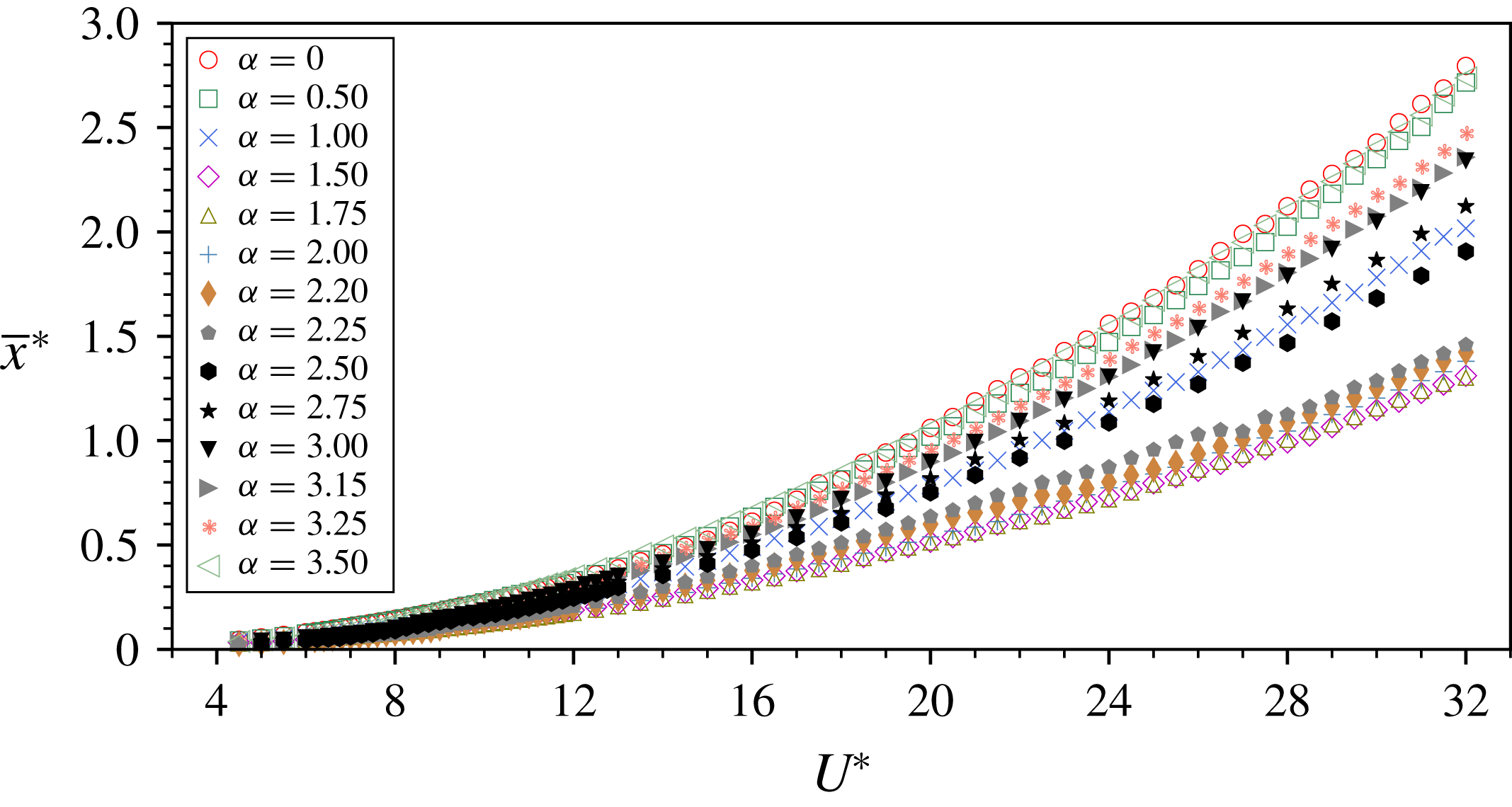
The time-averaged displacement as a function of the reduced velocity for the rotation rates investigated.

The time-averaged displacement of the cylinder from its neutral position at zero flow velocity as a function of
 $U^{\ast }$
is plotted in figure 4 for various rotation rates. It should be noted that the time-averaged displacement is denoted by
 $\bar{x}$
and its normalised form is given by
 $\bar{x}^{\ast }=\bar{x}/D$
. As shown,
 $\bar{x}^{\ast }$
decreases in magnitude as
 $\unicode[STIX]{x1D6FC}$
increases in the range
 $0\leqslant \unicode[STIX]{x1D6FC}\leqslant 1.75$
, and then it increases for higher
 $\unicode[STIX]{x1D6FC}$
values. This general behaviour agrees with the results of low-Reynolds-number
 $(Re=100)$
simulations of Bourguet & Lo Jacono (Reference Bourguet and Lo Jacono2015) that the time-averaged displacement of the cylinder decreased as
 $\unicode[STIX]{x1D6FC}$
was increased up to 2.7, prior to an increase with
 $\unicode[STIX]{x1D6FC}$
.
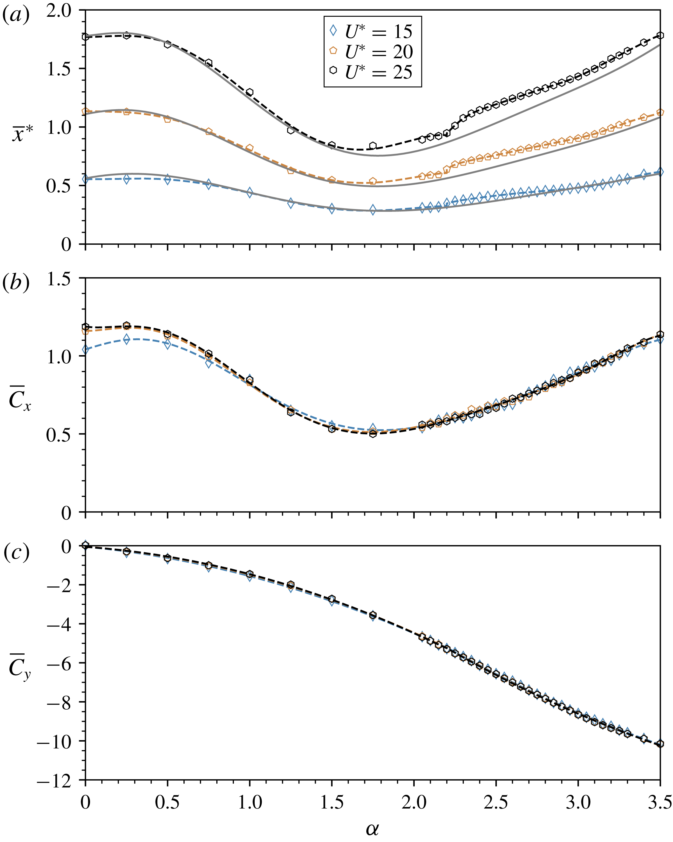
Measurements and estimation of
 $\bar{x}^{\ast }$
as a function of
 $\unicode[STIX]{x1D6FC}$
at three different
 $U^{\ast }$
values. In (a), the solid lines represent the estimated
 $\bar{x}^{\ast }$
based on the
 $\overline{C}_{x}$
of a rigidly mounted cylinder shown in (b) for each
 $U^{\ast }$
. In (c), the corresponding mean transverse lift is presented. The dashed lines represent the corresponding fifth-order polynomial fit curves for each
 $U^{\ast }$
.

To understand better the physics behind this behaviour, taking the temporal average of both sides of (2.1) gives
 $$\begin{eqnarray}\bar{x}=\frac{\bar{F}_{x}}{k},\end{eqnarray}$$
and, changing to the normalised form, this becomes
 $$\begin{eqnarray}\bar{x}^{\ast }=\frac{\unicode[STIX]{x1D70C}U^{2}L\overline{C}_{x}}{2k},\end{eqnarray}$$
where
 $\overline{C}_{x}=\overline{F}_{x}/(\unicode[STIX]{x1D70C}U^{2}DL/2)$
. Substitution from
 $U^{\ast }=U/(\,f_{nw}D)$
and
 $k\cong (2\unicode[STIX]{x03C0}f_{na})^{2}m$
then gives
 $$\begin{eqnarray}\bar{x}^{\ast }=\frac{\unicode[STIX]{x1D70C}(U^{\ast }f_{nw}D)^{2}L\overline{C}_{x}}{2(2\unicode[STIX]{x03C0}f_{na})^{2}m}.\end{eqnarray}$$
Further substitution of
 $m_{d}=\unicode[STIX]{x1D70C}\unicode[STIX]{x03C0}D^{2}L/4$
and
 $C_{A}=m_{A}/m_{d}=((\,f_{na}/f_{nw})^{2}-1)m^{\ast }$
yields
 $$\begin{eqnarray}\bar{x}^{\ast }=\frac{U^{\ast 2}\overline{C}_{x}}{2\unicode[STIX]{x03C0}^{3}(C_{A}+m^{\ast })}.\end{eqnarray}$$
Based on (3.4),
 $\bar{x}^{\ast }$
is examined as a function of
 $\unicode[STIX]{x1D6FC}$
at three different reduced velocities
 $U^{\ast }=15.0$
, 20.0 and 25.0 (corresponding to
 $Re=3936$
, 5247 and 6559) in figure 5(a). Along with this, the estimated values of
 $\bar{x}^{\ast }$
(represented by solid lines), determined by evaluating (3.4) with the measurements of
 $\overline{C}_{x}$
of the rigidly mounted cylinder case at the same reduced velocities as in figure 5(b), are also plotted. Remarkably, the estimated
 $\bar{x}^{\ast }$
predicts well its response in the actual vibration cases, although discrepancies do exist over the range of
 $2.2<\unicode[STIX]{x1D6FC}<3.0$
at
 $U^{\ast }=15.0$
and 25.0. These discrepancies are attributable to strong fluid–structure interaction characterised by large-amplitude oscillations in this
 $\unicode[STIX]{x1D6FC}$
range, which will be presented in § 3.1.2. Clearly, in all of the cases,
 $\bar{x}^{\ast }$
monotonically decreases to its minimum as
 $\unicode[STIX]{x1D6FC}$
increases up to 1.75, prior to a gradual increase for higher
 $\unicode[STIX]{x1D6FC}$
values. This trend resembles that seen for
 $\overline{C}_{x}$
of the rigidly mounted cylinder case in figure 5(b). Compared with the similar variation of
 $\bar{x}^{\ast }$
with
 $\unicode[STIX]{x1D6FC}$
observed by Bourguet & Lo Jacono (Reference Bourguet and Lo Jacono2015), where
 $\overline{C}_{x}$
of the rigidly mounted cylinder monotonically decreased as
 $\unicode[STIX]{x1D6FC}$
was increased over the range
 $0\leqslant \unicode[STIX]{x1D6FC}\leqslant 4$
at
 $Re=100$
(see Stojković et al.
Reference Stojković, Breuer and Durst2002; Bourguet & Lo Jacono Reference Bourguet and Lo Jacono2014), the present results reveal a strong relation to
 $\overline{C}_{x}$
of the rigidly mounted cylinder, despite some minor deficits between the measured and estimated
 $\bar{x}^{\ast }$
values.
It should be noted that as
 $\unicode[STIX]{x1D6FC}$
is further increased to around 2.2,
 $\bar{x}^{\ast }$
experiences a slight jump. This behaviour is associated with a jump in the amplitude response, which will be discussed in § 3.1.2. The results for
 $\overline{C}_{y}$
in figure 5(c) will be discussed in § 3.2.
3.1.2 Amplitude responses
The normalised vibration amplitude response (
 $A_{10}^{\ast }$
) about its time-averaged position as a function of
 $U^{\ast }$
is characterised for varying values of
 $\unicode[STIX]{x1D6FC}$
in figure 6. For clarity of the presentation, the
 $\unicode[STIX]{x1D6FC}$
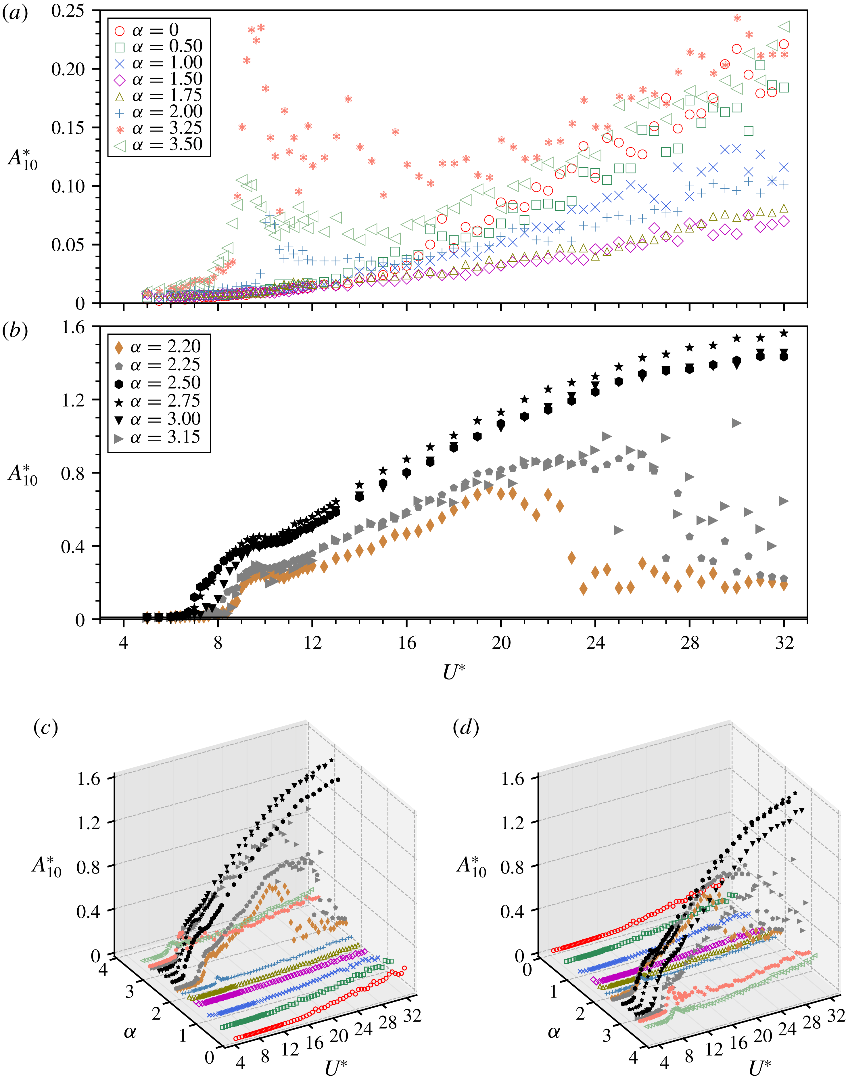
cases associated with small- and large-amplitude responses are plotted separately in figures 6(a) and 6(b), while figures 6(c) and 6(d) present the results in two different 3D views. As can be seen in the figure, for the low rotation rates (i.e.
 $\unicode[STIX]{x1D6FC}\leqslant 1.75$
), the vibration amplitude tends to become less responsive to the cylinder rotation with increasing
 $\unicode[STIX]{x1D6FC}$
up to 1.75, at which the minimum values of
 $\bar{x}^{\ast }$
and
 $\overline{C}_{x}$
of the rigidly mounted cylinder are observed. In this range of
 $\unicode[STIX]{x1D6FC}$
, the amplitude response appears to be scattered, and no ‘lock-in’ or synchronisation regions are identified over the reduced velocity range investigated (
 $5\leqslant U^{\ast }\leqslant 32$
). The maximum value of
 $A_{10}^{\ast }$
observed is 0.22 at
 $U^{\ast }=32$
. When the rotation rate is increased to
 $\unicode[STIX]{x1D6FC}=2.00$
, the amplitude response becomes slightly larger than that of
 $\unicode[STIX]{x1D6FC}=1.75$
. Of interest is a narrow synchronisation region present at
 $U^{\ast }\approx 10{-}10.4$
, characterised by a small jump in the
 $A_{10}^{\ast }$
response. This will be further clarified by the frequency response.
As the rotation rate is further increased to the range of
 $2.20\leqslant \unicode[STIX]{x1D6FC}\leqslant 3.15$
shown in figure 6(b), substantially larger oscillations are encountered. For
 $\unicode[STIX]{x1D6FC}=2.20$
, the cylinder vibration remains unresponsive to the rotation rate for
 $U^{\ast }$
up to 8.5 (figure 7
a.i). Further increase of
 $U^{\ast }$
results in a rapid increase in the amplitude response to reach a plateau with
 $A_{10}^{\ast }\approx 0.24$
at
 $U^{\ast }\approx 10$
, which is followed by a progressive increase trend towards a maximum value of
 $A_{10}^{\ast }=0.72$
at
 $U^{\ast }=19.5$
. Over this
 $U^{\ast }$
range, the body oscillations are strongly periodic, with the oscillation frequency synchronised with the dominant frequency of the fluid forcing. The periodicity in this
 $U^{\ast }$
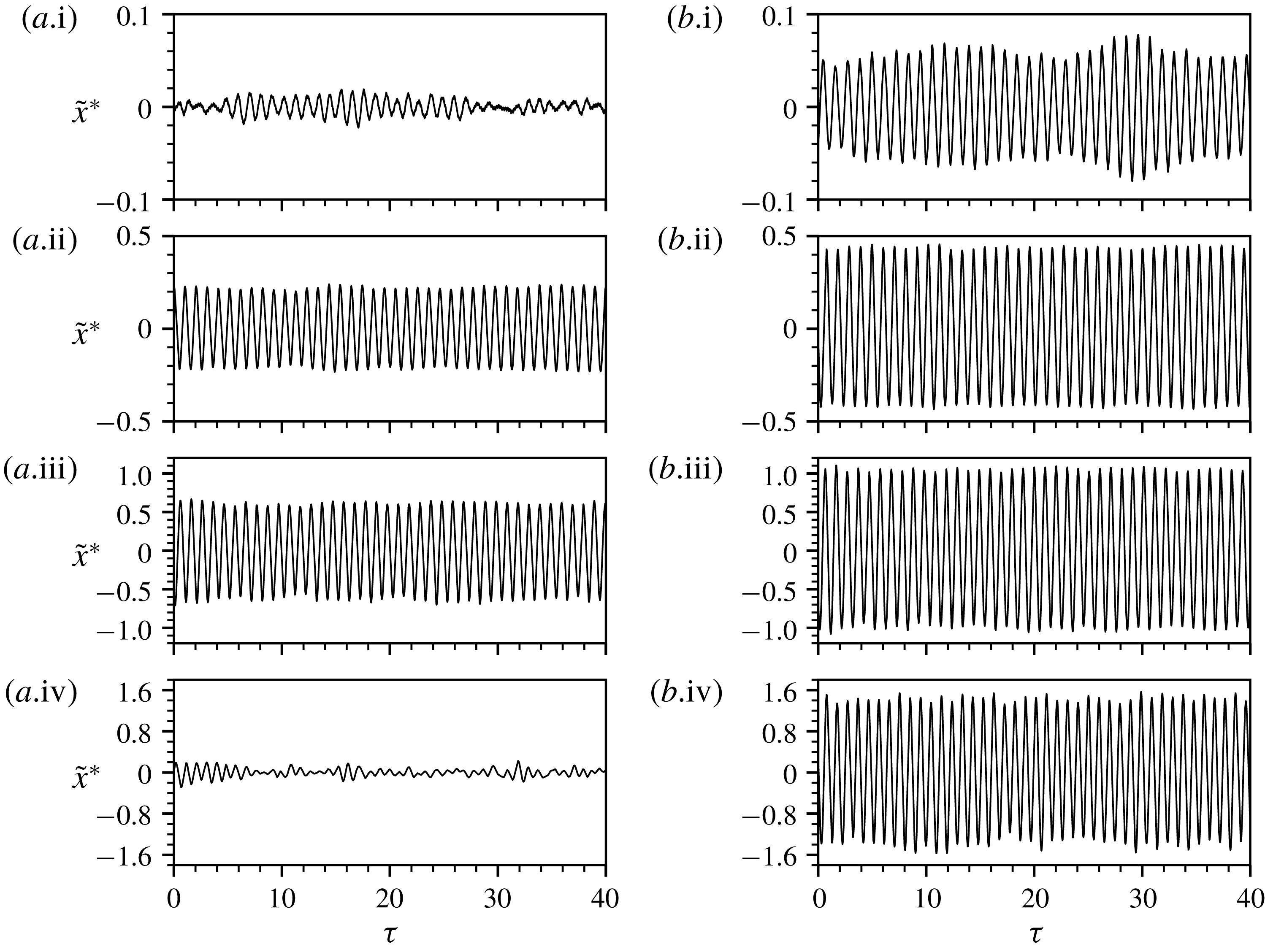
range is illustrated by the time traces of the cylinder vibration in figure 7(a.ii,a.iii). After this, the
 $A_{10}^{\ast }$
response fluctuates slightly and then drops sharply to
 $A_{10}^{\ast }\approx 0.17$
at
 $U^{\ast }=22.5$
. Associated with this drop, the time-averaged position shown in figure 4 deviates slightly from its original trend in the lower
 $U^{\ast }$
range. For higher
 $U^{\ast }$
, the cylinder oscillations exhibit much less periodicity, with
 $A_{10}^{\ast }$
values fluctuating around 0.22 (figure 7
a.iv), indicating that the fluid–structure interaction becomes desynchronised. For the case of
 $\unicode[STIX]{x1D6FC}=2.25$
, the vibration response in general appears to be similar to that of
 $\unicode[STIX]{x1D6FC}=2.20$
; however, the fluid–structure synchronisation region occurs at slightly lower reduced velocity
 $U^{\ast }=8.0$
and covers a wider range of reduced velocity up to
 $U^{\ast }=26.5$
; the
 $A_{10}^{\ast }$
response sees its maximum value of
 $0.90$
at
 $U^{\ast }=26$
, prior to a sudden drop leading to the desynchronised region for high
 $U^{\ast }$
. Moreover, similar to that seen for
 $\unicode[STIX]{x1D6FC}=2.20$
, a slight dip in the
 $\bar{x}^{\ast }$
trend associated with this sudden drop in
 $A_{10}^{\ast }$
is observed at
 $U^{\ast }=26.5$
in figure 4.
The normalised amplitude response
 $A_{10}^{\ast }$
as a function of
 $U^{\ast }$
for varying values of
 $\unicode[STIX]{x1D6FC}$
. The cases of small- and large-amplitude responses are shown separately in (a) and (b); (c) and (d) show the results in two different auxiliary 3D views.

For the cases of
 $\unicode[STIX]{x1D6FC}=2.50$
and 2.75 (highlighted in black symbols), the onset of the fluid–structure synchronisation tends to occur at an even lower reduced velocity (i.e.
 $U^{\ast }=7.2$
) than that of the other lower
 $\unicode[STIX]{x1D6FC}$
values. Moreover, the
 $A_{10}^{\ast }$
response increases rapidly to reach a plateau with
 $A_{10}^{\ast }\approx 0.40$
for
 $\unicode[STIX]{x1D6FC}=2.50$
and
 $A_{10}^{\ast }\approx 0.46$
for
 $\unicode[STIX]{x1D6FC}=2.75$
over the range of
 $9\leqslant U^{\ast }\leqslant 11$
. Interestingly, the synchronisation persists, with the amplitude response increasing monotonically and unboundedly for the rest of the
 $U^{\ast }$
range investigated. As illustrated in figure 7(b.ii–b.iv), the body oscillations remain highly periodic. It should be noted that the synchronisation was observed to exist for up to
 $U^{\ast }=40$
in other tests (not shown here) that used the same experimental model with softer springs for lower
 $f_{nw}$
values to extend the range of
 $U^{\ast }$
. In general, the amplitude response tends to increase with increasing
 $\unicode[STIX]{x1D6FC}$
for moderate rotation rates (i.e.
 $2.20\leqslant \unicode[STIX]{x1D6FC}\leqslant 2.75$
). The peak value of
 $A_{10}^{\ast }$
in the parameter space under study is observed to be
 $1.56$
at
 $(\unicode[STIX]{x1D6FC},U^{\ast })=(2.75,32)$
. When the rotation rate is further increased to
 $\unicode[STIX]{x1D6FC}=3.00$
, the onset of the synchronisation reverses to
 $U^{\ast }\approx 7.6$
, which is in between those for
 $\unicode[STIX]{x1D6FC}=2.25$
and 2.75. In addition, the
 $A_{10}^{\ast }$
response becomes lower than that of
 $\unicode[STIX]{x1D6FC}=2.75$
. As the rotation rate is further increased to
 $\unicode[STIX]{x1D6FC}=3.15$
, the vibration response generally resembles that seen for the cases of
 $\unicode[STIX]{x1D6FC}=2.20$
and 2.25.
At high rotation rates (i.e.
 $\unicode[STIX]{x1D6FC}=3.25$
and 3.50), the vibration response appears to be similar to that for
 $\unicode[STIX]{x1D6FC}=2.00$
, but with a more distinct synchronisation region around
 $U^{\ast }=9$
. The
 $A_{10}^{\ast }$
response exhibits similar magnitude to the non-rotating case (
 $\unicode[STIX]{x1D6FC}=0$
) for high reduced velocities (
 $U^{\ast }>24$
).
Time traces of the cylinder oscillations for (a)
 $\unicode[STIX]{x1D6FC}=2.20$
and (b)
 $\unicode[STIX]{x1D6FC}=2.75$
at
 $U^{\ast }=7.0$
, 10.0, 19.5 and 30.0 in (i–iv), respectively. Strongly periodic oscillations are observed in the synchronisation region, as illustrated in (a.ii,a.iii) and (b.ii–b.iv). It should be noted that
 $\tilde{x}^{\ast }$
denotes the normalised oscillatory component of the cylinder motion;
 $\unicode[STIX]{x1D70F}=tf_{nw}$
is the normalised time.

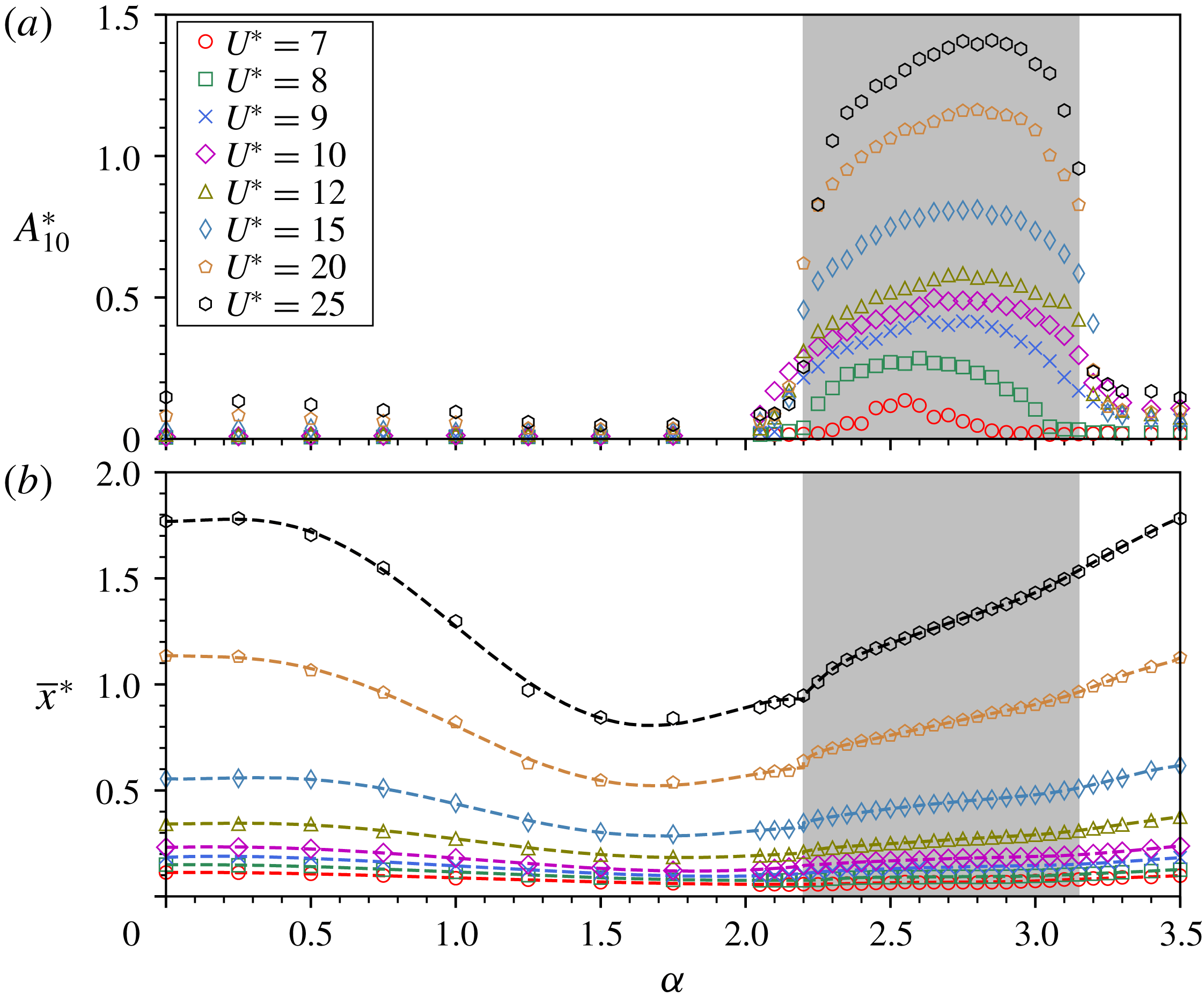
The vibration response as a function of the rotation rate at different reduced velocities. (a) The normalised amplitude responses; (b) the normalised time-averaged displacement. In (b), the dashed lines represent the fifth-order polynomial fit curves for each case of
 $U^{\ast }$
.

To show better the effects of body rotation on the vibration response, the vibration response as a function of
 $\unicode[STIX]{x1D6FC}$
is investigated here for different fixed
 $U^{\ast }$
values. Figure 8 shows (a) the
 $A_{10}^{\ast }$
response and (b) its time-averaged position as a function of
 $\unicode[STIX]{x1D6FC}$
at several
 $U^{\ast }$
values of interest. The selection of these
 $U^{\ast }$
values was based on how each represents the dynamic response (i.e. the magnitudes of
 $A_{10}^{\ast }$
,
 $C_{x}$
and
 $C_{y}$
) at similar
 $U^{\ast }$
and how the dynamic response evolves with increasing
 $U^{\ast }$
. As can be seen in the figure, the cylinder vibrations remain very unresponsive (
 $A_{10}^{\ast }\lesssim 0.2$
) to the body rotation over the low range
 $\unicode[STIX]{x1D6FC}\leqslant 1.75$
. In this
 $\unicode[STIX]{x1D6FC}$
range, the
 $A_{10}^{\ast }$
responses, if they are detectable, tend to reduce to minimum with increasing
 $\unicode[STIX]{x1D6FC}$
, as do the
 $\bar{x}^{\ast }$
trends. For the moderate range
 $2.20\leqslant \unicode[STIX]{x1D6FC}\leqslant 3.15$
highlighted in the grey region, significantly larger-amplitude oscillations are encountered generally, while the wake–body synchronisation regions and amplitude magnitudes depend on
 $U^{\ast }$
. In addition, the
 $\unicode[STIX]{x1D6FC}$
value at which peak
 $A_{10}^{\ast }$
occurs shifts as
 $U^{\ast }$
increases, i.e. from
 $\unicode[STIX]{x1D6FC}=2.50$
with
 $A_{10}^{\ast }=0.14$
at
 $U^{\ast }=7.0$
to
 $\unicode[STIX]{x1D6FC}=2.85$
with
 $A_{10}^{\ast }=1.41$
at
 $U^{\ast }=25.0$
. Of particular interest is the vibration for higher rotation rates
 $\unicode[STIX]{x1D6FC}\geqslant 3.20$
, where the oscillation amplitudes drop substantially to low values, e.g.
 $A_{10}^{\ast }\approx 0.2$
for
 $U^{\ast }=25.0$
. This differs significantly from the low-
 $Re$
results of Bourguet & Lo Jacono (Reference Bourguet and Lo Jacono2015), where the cylinder oscillations increase with
 $\unicode[STIX]{x1D6FC}$
for a given
 $U^{\ast }$
in the second vibration region (
 $\unicode[STIX]{x1D6FC}\geqslant 2.7$
).
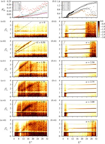
3.1.3 Frequency responses
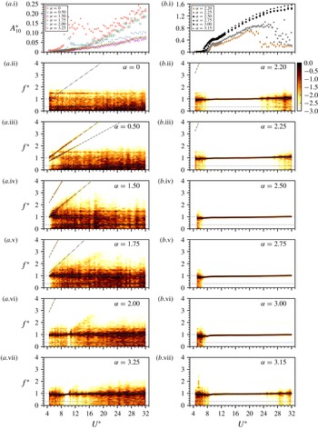
Logarithmic-scale PSD contour plots of the normalised frequency response of cylinder vibration as a function of
 $U^{\ast }$
for varying
 $\unicode[STIX]{x1D6FC}$
. The low-amplitude-response cases are plotted in (a) and the large-amplitude-response cases in (b). It should be noted that the frequency components are normalised by
 $f_{nw}$
, i.e.
 $f^{\ast }=f/f_{nw}$
. The dot-dashed lines represent the vortex-shedding frequency (Strouhal frequency) of the rigidly mounted cylinder case. The dashed lines denote the normalised rotation frequency
 $|\unicode[STIX]{x1D6FA}|/2\unicode[STIX]{x03C0}f_{nw}$
. The horizontal dotted lines highlight the frequency values at
 $f^{\ast }\in \{1/3,1\}$
.

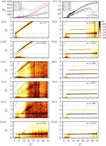
Logarithmic-scale PSD contour plots of the normalised frequency response of the streamwise fluid force (
 $C_{x}$
) as a function of
 $U^{\ast }$
for varying
 $\unicode[STIX]{x1D6FC}$
. The low-amplitude-response cases are plotted in (a) and the large-amplitude-response cases in (b). The horizontal dotted lines highlight the frequency values at
 $f_{C_{x}}^{\ast }\in \{1/3,1,2,3\}$
.

Logarithmic-scale PSD contour plots of the normalised frequency response of the transverse fluid force (
 $C_{y}$
) as a function of
 $U^{\ast }$
for varying
 $\unicode[STIX]{x1D6FC}$
. The low-amplitude-response cases are plotted in (a) and the large-amplitude-response cases in (b). The horizontal dotted lines highlight the frequency values at
 $f_{C_{x}}^{\ast }\in \{1/3,1,2,3\}$
.

Many previous studies (e.g. Zhao et al. Reference Zhao, Leontini, Lo Jacono and Sheridan2014b ; Bourguet & Lo Jacono Reference Bourguet and Lo Jacono2015) concerning FIV of bluff bodies have shown that large-amplitude oscillations are associated with wake–body synchronisation. In order to provide insights into the fluid–structure mechanisms of wake–body synchronisation, a frequency spectrum analysis is presented in this subsection.
Figures 9–11 show the normalised logarithmic-scale PSD contours of the frequency response of the body vibration (
 $\,f^{\ast }$
), the streamwise fluid force (
 $\,f_{C_{x}}^{\ast }$
) and the transverse lift force (
 $\,f_{C_{y}}^{\ast }$
), respectively, as a function of
 $U^{\ast }$
for varying
 $\unicode[STIX]{x1D6FC}$
. In these figures, for clarity of the presentation, the
 $\unicode[STIX]{x1D6FC}$
cases associated with low-amplitude responses are plotted in (a) while the cases with large-amplitude responses are plotted in (b).
In the absence of cylinder rotation (
 $\unicode[STIX]{x1D6FC}=0$
), where the body oscillations appear to be broadly non-periodic with fluctuating amplitudes tending to increase with
 $U^{\ast }$
(see figure 9
a.i), the frequency responses
 $f^{\ast }$
and
 $f_{C_{x}}^{\ast }$
in figures 9(a.ii) and 10(a.ii), respectively, reveal that while broadband noise appears with relatively strong intensity over the entire spectra, the subharmonic at
 $f_{nw}/3$
(or
 $f^{\ast }=1/3$
) highlighted by a dotted line is found to be dominant throughout the
 $U^{\ast }$
range investigated. As expected, on the other hand, the response of
 $f_{C_{y}}^{\ast }$
follows the Strouhal vortex-shedding trend highlighted by the dot-dashed line in figure 11(a.ii).
For low rotation rates
 $\unicode[STIX]{x1D6FC}=0.50\text{ and }1.50$
, the one-third subharmonic remains consistently in the responses of
 $f^{\ast }$
and
 $f_{C_{x}}^{\ast }$
in figures 9(a.iii,a.iv) and 10(a.iii,a.iv), respectively. In addition, there are two frequency components clearly associated with the vortex shedding and the body rotation, as indicated by the dot-dashed and dashed lines, respectively. Spot measurements (not shown) on a rigidly mounted cylinder found that the resulting Strouhal numbers increase substantially with rotation rates for this
 $\unicode[STIX]{x1D6FC}$
range, i.e. from
 $St\simeq 0.206$
at
 $\unicode[STIX]{x1D6FC}=0$
to
 $St\simeq 0.239$
at
 $\unicode[STIX]{x1D6FC}=1.50$
. However, the responses of
 $f_{C_{y}}^{\ast }$
in figure 11(a.ii–a.iv) indicate that the vortex shedding is gradually attenuated as
 $\unicode[STIX]{x1D6FC}$
increases, presumably leading to suppression of the amplitude response. For the next higher rotation rate
 $\unicode[STIX]{x1D6FC}=1.75$
, the vortex shedding appears to be fully suppressed, as evidenced by the appearance of broadband noise in the entire spectrum in figure 11(a.v). This means that the fluctuating fluid forcing component is reduced to a minimum. Indeed, this also sees minimum vibration magnitudes.
When the rotation rate is further increased to
 $\unicode[STIX]{x1D6FC}=2.00$
, the dominant frequency of body oscillation switches to be approximately
 $f^{\ast }=1$
, but still with broadband noise obviously shown in figure 9(a.vi). Here, it should be noted that a very narrow wake–body synchronisation region occurs over
 $10.0\lesssim U^{\ast }\lesssim 10.4$
, with the dominant frequency components of the periodic body oscillations matching those of the fluid forces, on the basis that the fluid forces arise from the wake dynamics. This sees a small ride-up in the
 $A_{10}^{\ast }$
response previously described in § 3.1.2.
Strikingly, as the rotation is still further increased to
 $\unicode[STIX]{x1D6FC}=2.20$
, the wake–body synchronisation region becomes dramatically widened over the reduced velocity range
 $8.5\lesssim U^{\ast }\lesssim 19.5$
as in § 3.1.2. Within this synchronisation region, a number of interesting features are immediately apparent from inspection of the corresponding amplitude response and frequency PSD contour plots shown in figures 9–11. All three of the PSD contour plots in (b.ii) of figures 9–11 exhibit a very clear composition of frequency components, which is indicative of highly periodic body oscillations as a result of strong fluid–structure interaction. Of particular interest is the appearance of the second and third harmonic frequencies (i.e.
 $f^{\ast }=2$
and 3) in both of the two fluid force components and also synchronisation of their harmonics. In the previous studies of Zhao et al. (Reference Zhao, Leontini, Lo Jacono and Sheridan2014b
) and Wang et al. (Reference Wang, Du, Zhao and Sun2017) concerning transverse FIV, it was suggested that large-amplitude oscillations associated with strong fluid–structure interaction were attributable to harmonic synchronisations. Similarly, Bourguet & Lo Jacono (Reference Bourguet and Lo Jacono2015) observed in in-line FIV of a rotating cylinder that the wake–body synchronisation that involved harmonics of the flow velocity in the wake and the streamwise force led to galloping response in the second vibration region, where oscillation amplitudes appeared to increase unboundedly but not monotonically with
 $U^{\ast }$
. In addition to the harmonic contributions to large-amplitude oscillations, the present results also demonstrate that the frequency of the streamwise force of a freely vibrating cylinder can be modulated by body rotation to be synchronised with that of the transverse force. Associated with such harmonic synchronisation, the amplitude response behaves in a VIV synchronisation behaviour for a low reduced velocity range
 $8.5\lesssim U^{\ast }\lesssim 10.8$
, where well-defined vortex shedding is found to be synchronised with cylinder oscillations; it then develops in a rotation-induced galloping behaviour with a linear growth trend for
 $10.8<U^{\ast }\lesssim 19.5$
. As it is induced by the body rotation, this type of vibration response is named rotation-induced galloping, to differentiate from the conventional transverse galloping. It should be noted that the boundary between the VIV synchronisation and rotation-induced galloping regimes is identified based on the onset of the monotonic amplitude growth trend. Significantly different from conventional transverse galloping of a bluff body (e.g. square cylinder), which is commonly found to be dominated by a frequency much lower than the natural frequency of the system, this rotation-induced galloping response is dominated by the frequency component matching
 $f_{nw}$
. However, it cannot be maintained for higher reduced velocities outside the synchronisation region. All of these vibrational features are also observed at the slightly higher rotation rate
 $\unicode[STIX]{x1D6FC}=2.25$
, however with a slightly wider harmonic synchronisation. As expected from the amplitude responses previously discussed, further increase of the rotation rate to higher values
 $\unicode[STIX]{x1D6FC}=2.50$
, 2.75 and 3.00 means that, as a result of stronger fluid–structure enhanced by cylinder rotation, harmonic synchronisations persist unboundedly as
 $U^{\ast }$
is increased (see figures 9
b.iv–b.vi–11
b.iv–b.vi).
Nevertheless, a rotation-induced galloping response occurs within a limited
 $\unicode[STIX]{x1D6FC}$
range up to 3.15, at which the amplitude and frequency responses (see figures 9
b.vii–11
b.vii) resemble those seen in the earlier cases of
 $\unicode[STIX]{x1D6FC}=2.20$
and 2.25. Similarly, beyond
 $\unicode[STIX]{x1D6FC}=3.15$
, the vibration response (e.g.
 $\unicode[STIX]{x1D6FC}=3.25$
shown in figures 9–11
a.vii) resembles that seen for
 $\unicode[STIX]{x1D6FC}=2.00$
.
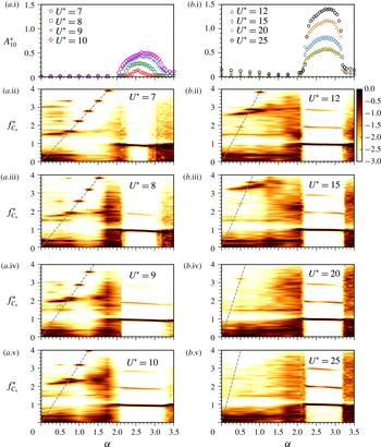
Logarithmic-scale frequency PSD contour plots of the streamwise fluid force (
 $C_{x}$
) as a function of
 $\unicode[STIX]{x1D6FC}$
at different fixed
 $U^{\ast }$
values. The
 $U^{\ast }$
cases from the VIV synchronisation region are plotted in (a) and the
 $U^{\ast }$
cases from the rotation-induced galloping region in (b). The dashed lines denote the normalised rotation frequency
 $|\unicode[STIX]{x1D6FA}|/2\unicode[STIX]{x03C0}f_{nw}$
.

To show more clearly the effects of body rotation on harmonic synchronisation regions, the vibration response as a function of
 $\unicode[STIX]{x1D6FC}$
for different fixed
 $U^{\ast }$
values (the same as in figure 8) is plotted in figure 12. Four cases with VIV synchronisation response are presented in (a), while other four cases with rotation-induced galloping response are plotted in (b). As can be seen in the figure, harmonic synchronisation regions are generally encountered over the range
 $2.20\lesssim \unicode[STIX]{x1D6FC}\lesssim 3.20$
, except for the cases
 $U^{\ast }=9.0$
and 10.0, showing that the harmonic synchronisation regions may exceed
 $\unicode[STIX]{x1D6FC}=3.5$
.
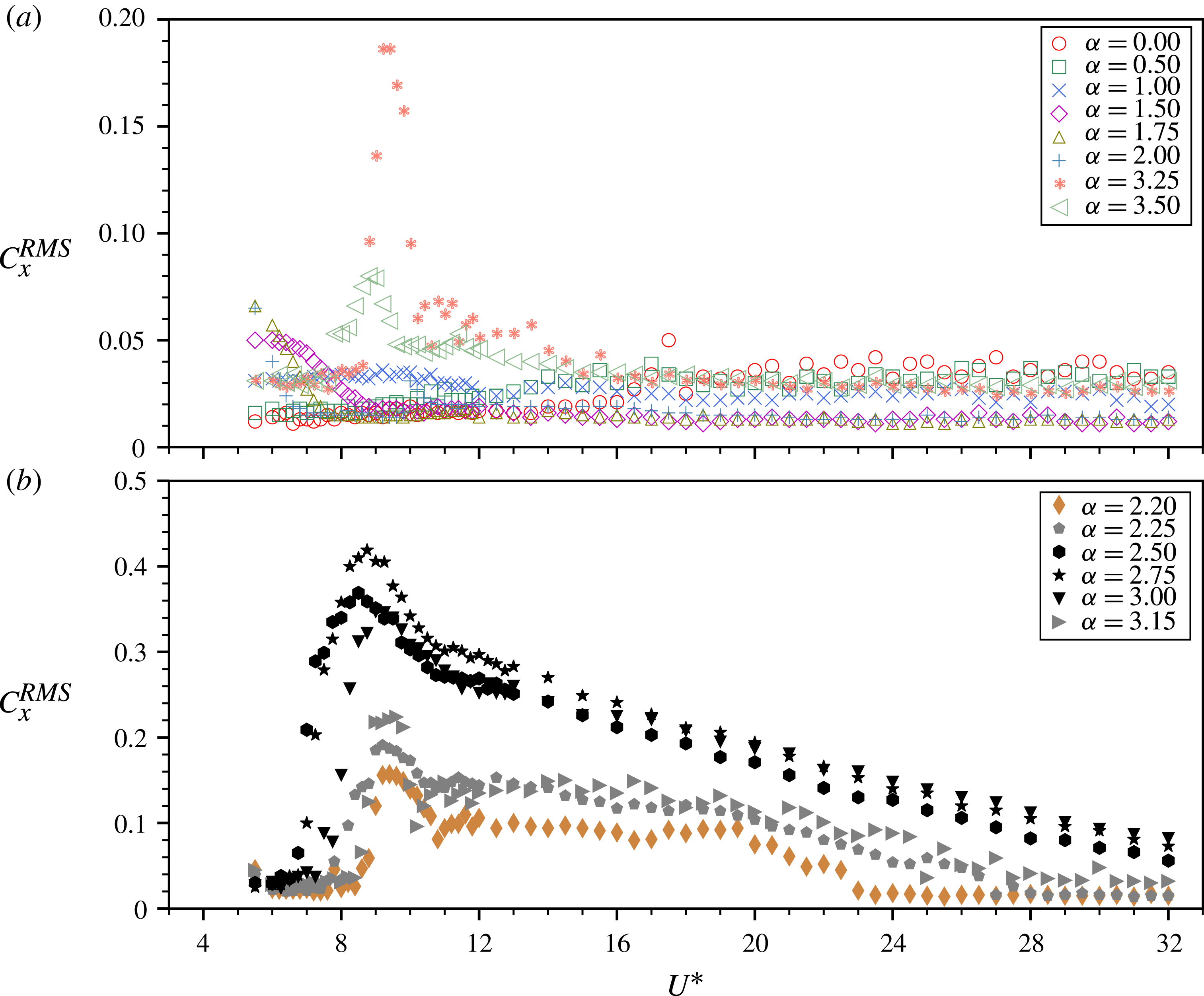
3.2 Fluid forces
The fluctuating component of the streamwise fluid force
 $C_{x}^{RMS}$
as a function of
 $U^{\ast }$
for various fixed
 $\unicode[STIX]{x1D6FC}$
values. The
 $\unicode[STIX]{x1D6FC}$
cases associated with small- and large-amplitude responses are shown separately in (a) and (b).

The transverse lift coefficient components as a function of
 $U^{\ast }$
for various fixed
 $\unicode[STIX]{x1D6FC}$
values. (a) The time-averaged component for all the fixed
 $\unicode[STIX]{x1D6FC}$
cases tested. (b,c) The r.m.s. components for the cases associated with small- and large-amplitude responses, respectively.

The time-averaged and fluctuating components of the transverse lift as a function of
 $\unicode[STIX]{x1D6FC}$
at different
 $U^{\ast }$
values. The dashed lines in (a) represent the fifth-order polynomial fit curve for each
 $U^{\ast }$
case. The solid line in (c) represents the polynomial fit curve through all of the measurements of the rigidly mounted cylinder case in figure 5(c). The symbol legend is given in (d). The area shaded in grey highlights the region (
 $2.20\leqslant \unicode[STIX]{x1D6FC}\leqslant 3.15$
) associated with significant body oscillations.

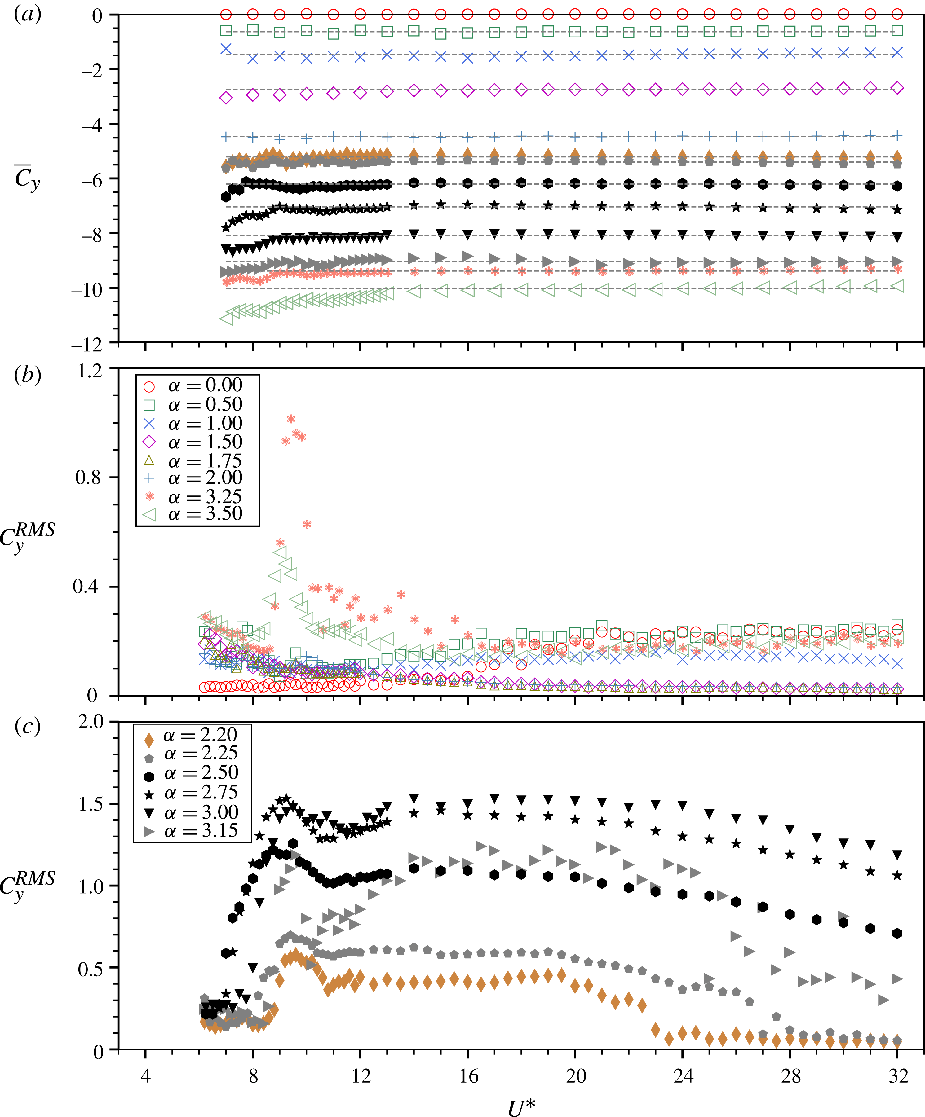
In this subsection, the focus is on the effect of cylinder rotation on the coefficients of the fluid forces over the parameter space under study. In addition, the phases of the transverse lift and vortex forces with respect to cylinder displacement will also be discussed.
The fluctuating component of the streamwise force is intrinsically coupled with the body vibration. Figure 13 presents the variation of the root-mean-square (r.m.s.) coefficient of the streamwise fluid force (
 $C_{x}^{RMS}$
) with
 $U^{\ast }$
for varying
 $\unicode[STIX]{x1D6FC}$
. As can be seen in figure 13(a),
 $C_{x}^{RMS}$
in the cases without a VIV synchronisation region (i.e.
 $0\leqslant \unicode[STIX]{x1D6FC}\leqslant 1.75$
) remains relatively constant and under 0.05 through the
 $U^{\ast }$
range investigated, whereas it is observed to surge to reach a peak value of 0.19 at
 $U^{\ast }=9.0$
in the VIV synchronisation region of
 $\unicode[STIX]{x1D6FC}=3.25$
. Similarly, for the cases with large-amplitude response in figure 13(b),
 $C_{x}^{RMS}$
increases dramatically at the beginning of the synchronisation region to reach its peak at
 $U^{\ast }=9.0$
, and then decreases sharply for reduced velocities up to
 $U^{\ast }\approx 11$
. The peak
 $C_{x}^{RMS}$
values of the largest-amplitude-response cases (i.e.
 $\unicode[STIX]{x1D6FC}=2.50$
, 2.75 and 3.00) are almost two times those of the other cases, e.g. 0.42 at
 $\unicode[STIX]{x1D6FC}=2.75$
compared with 0.23 of
 $\unicode[STIX]{x1D6FC}=3.15$
. For rotation-induced galloping regions at higher reduced velocities (
 $U^{\ast }\gtrsim 12$
),
 $C_{x}^{RMS}$
decreases monotonically and gradually.
Figure 14 shows the time-averaged (
 $\overline{C}_{y}$
) and fluctuating (
 $C_{y}^{RMS}$
) components of the transverse lift as a function of
 $U^{\ast }$
for the same fixed
 $\unicode[STIX]{x1D6FC}$
values. Clearly, due to the Magnus effect, the magnitude of
 $\overline{C}_{y}$
increases with
 $\unicode[STIX]{x1D6FC}$
. In general,
 $\overline{C}_{y}$
remains constant as
 $U^{\ast }$
is varied, despite some minor deviations occurring at low reduced velocities (
 $U^{\ast }\lesssim 12$
) for high rotation rates (
 $\unicode[STIX]{x1D6FC}\geqslant 2.20$
). This is significantly different from the low-Reynolds-number results of Bourguet & Lo Jacono (Reference Bourguet and Lo Jacono2015), where substantial fluctuations of
 $\overline{C}_{y}$
in accordance with the amplitude response were globally encountered in the second vibration region. On the other hand, the fluctuating part
 $C_{y}^{RMS}$
in figure 14(b,c) exhibits similar trends versus
 $U^{\ast }$
to those of
 $C_{x}^{RMS}$
. It should be noted that the magnitudes of
 $C_{y}^{RMS}$
in the rotation-induced galloping regions decrease only marginally compared with those peaks observed in the VIV synchronisation regions.
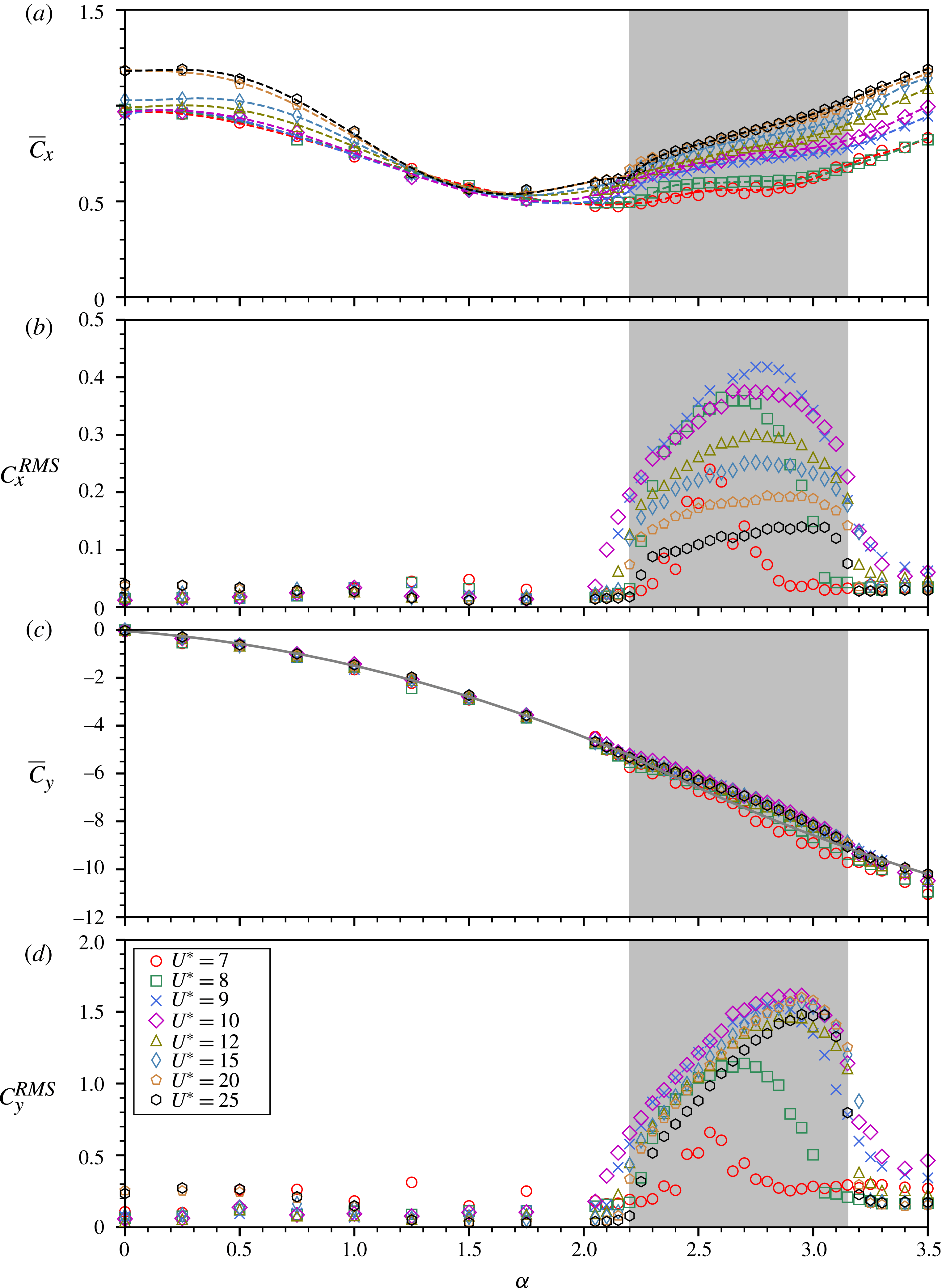
The effect of cylinder rotation on the fluid forces is further examined by plotting the coefficients of their components as a function of
 $\unicode[STIX]{x1D6FC}$
for various fixed
 $U^{\ast }$
values in figure 15. In addition to the results previously given in figure 5(a), 15(a) shows the variation of
 $\overline{C}_{x}$
with
 $\unicode[STIX]{x1D6FC}$
for more
 $U^{\ast }$
values covering a much wider range. In all of the cases, the minimum value of
 $\overline{C}_{x}$
is observed to be at
 $\unicode[STIX]{x1D6FC}\simeq 1.75$
. Moreover, these measurements of
 $\overline{C}_{x}$
are consistent with the observations of
 $\bar{x}^{\ast }$
in figure 8(b). On the other hand, the magnitude of
 $\overline{C}_{y}$
is found to increase quadratically with
 $\unicode[STIX]{x1D6FC}$
(see figure 15
c). By comparing with the case of a rigidly mounted cylinder, subtle deviations in
 $\overline{C}_{y}$
due to body oscillations are observed in the range of
 $2.50\leqslant \unicode[STIX]{x1D6FC}\leqslant 3.00$
. This suggests that the cylinder vibration has little effect on the transverse Magnus force in the parameter space under study. Furthermore, the results for the fluctuating components
 $C_{x}^{RMS}$
and
 $C_{y}^{RMS}$
presented in figures 15(b) and 15(d), respectively, are consistent with the corresponding
 $A_{10}^{\ast }$
response in figure 8(a). Similarly to the
 $A_{10}^{\ast }$
response, the
 $\unicode[STIX]{x1D6FC}$
value for the occurrence of the peak
 $C_{x}^{RMS}$
and
 $C_{y}^{RMS}$
also tends to shift from
 $\unicode[STIX]{x1D6FC}=2.50$
at
 $U^{\ast }=7.0$
to
 $\unicode[STIX]{x1D6FC}=2.85$
at 25.0. It appears that the imposed rotation enhances the fluctuating components of the fluid forces, and, in turn, they lead to increased oscillation amplitudes.
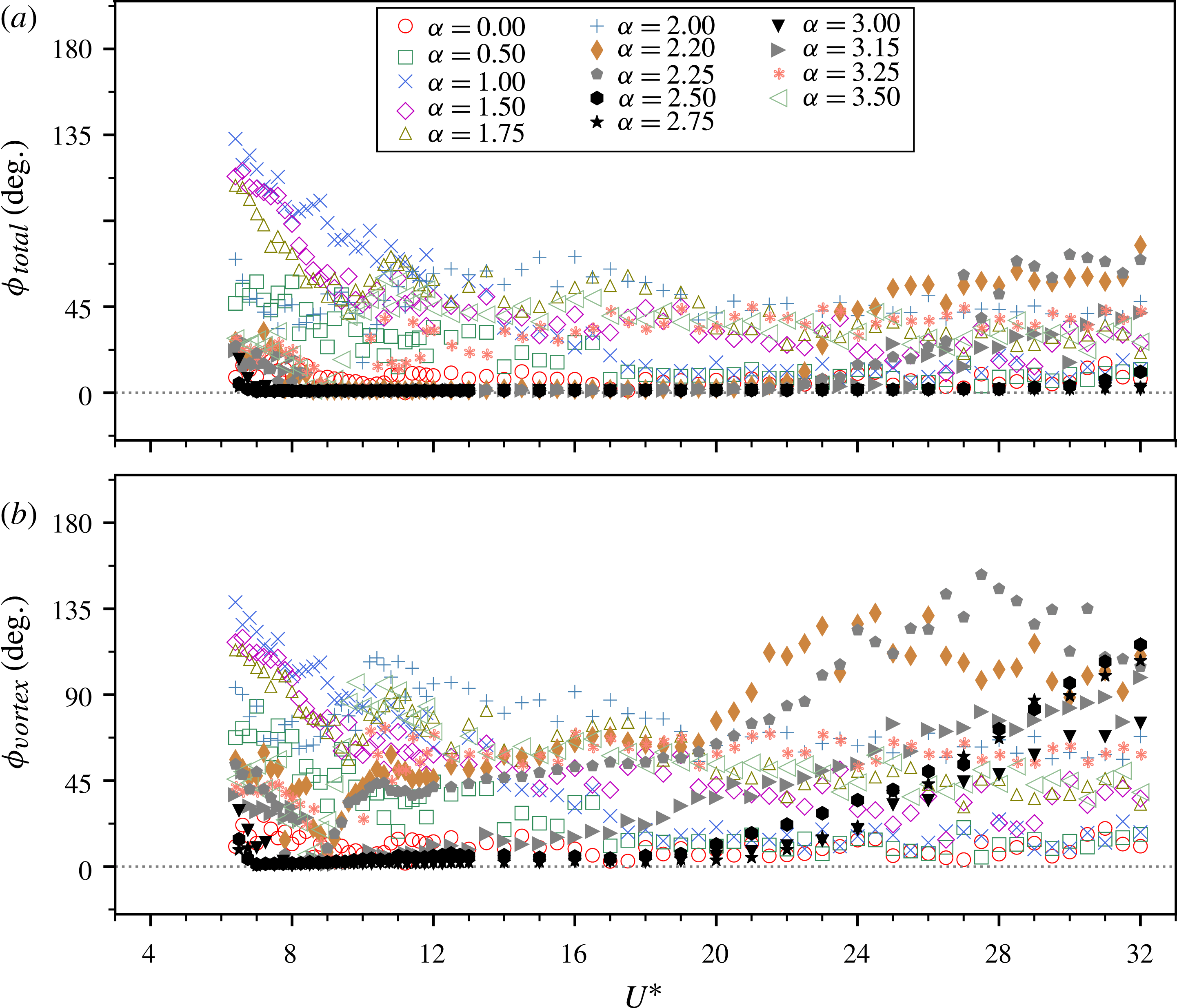
The total phase (a) and the vortex phase (b) as a function of
 $U^{\ast }$
for varying
 $\unicode[STIX]{x1D6FC}$
values (as in figure 4). The symbol legend is given in (a).

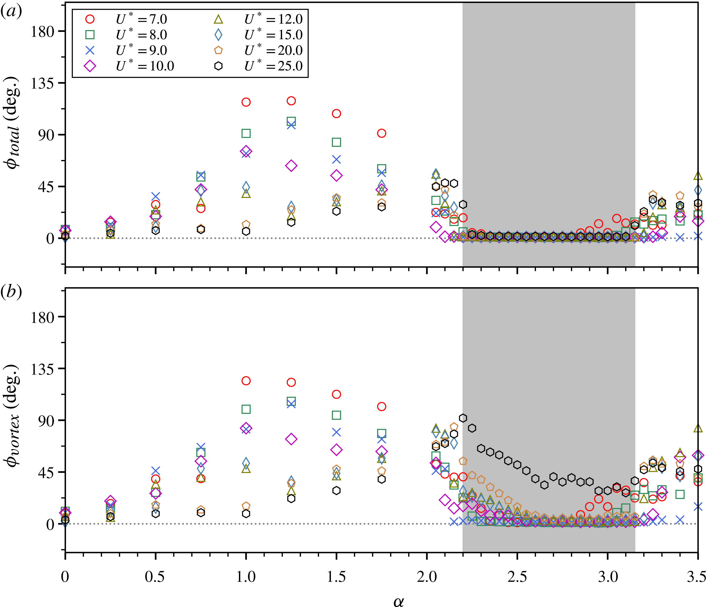
The total phase (a) and the vortex phase (b) as a function
 $\unicode[STIX]{x1D6FC}$
for various fixed
 $U^{\ast }$
values (as in figure 8). The symbol legend is given in (a). The area shaded in grey highlights the region (
 $2.20\leqslant \unicode[STIX]{x1D6FC}\leqslant 3.15$
) associated with significant body oscillations.

Figures 16–17 present the total and vortex phases as a function of
 $U^{\ast }$
and
 $\unicode[STIX]{x1D6FC}$
, respectively. Here, the total phase (
 $\unicode[STIX]{x1D719}_{total}$
) is defined as the phase angle between the streamwise fluid force and the cylinder displacement; the vortex phase (
 $\unicode[STIX]{x1D719}_{vortex}$
) is defined as the phase angle between the vortex force and the cylinder displacement, where the vortex force is computed based on
 $F_{vortex}=F_{x}-F_{potential}$
, with
 $F_{potential}=-C_{A}m_{d}\ddot{x}(t)$
the potential force, in a manner similar to that conducted in the transverse-only FIV studies of Govardhan & Williamson (Reference Govardhan and Williamson2000) and Zhao et al. (Reference Zhao, Leontini, Lo Jacono and Sheridan2014b
). As is evident from the figure, the total phase fluctuates broadly in the band between
 $0^{\circ }$
and
 $135^{\circ }$
in the desynchronised region, whereas it remains consistently close to
 $0^{\circ }$
throughout the harmonic synchronisation regions (e.g. see figure 17
a). Zero total phase means that the fluid forcing is in phase with the cylinder movement, which would potentially enhance the vibration amplitude. Such a situation is commonly seen in galloping. Thus, it is not surprising that a rotation-induced galloping response is encountered at high reduced velocities in harmonic synchronisation regions. On the other hand, the vortex phase, in general, behaves similarly to the total phase; however, it tends to increase gradually with
 $U^{\ast }$
for
 $U^{\ast }\gtrsim 20$
in the rotation-induced galloping region. This may correlate with gradual changes in the wake structure, as will be discussed in the following section § 3.3.
3.3 Wake structures
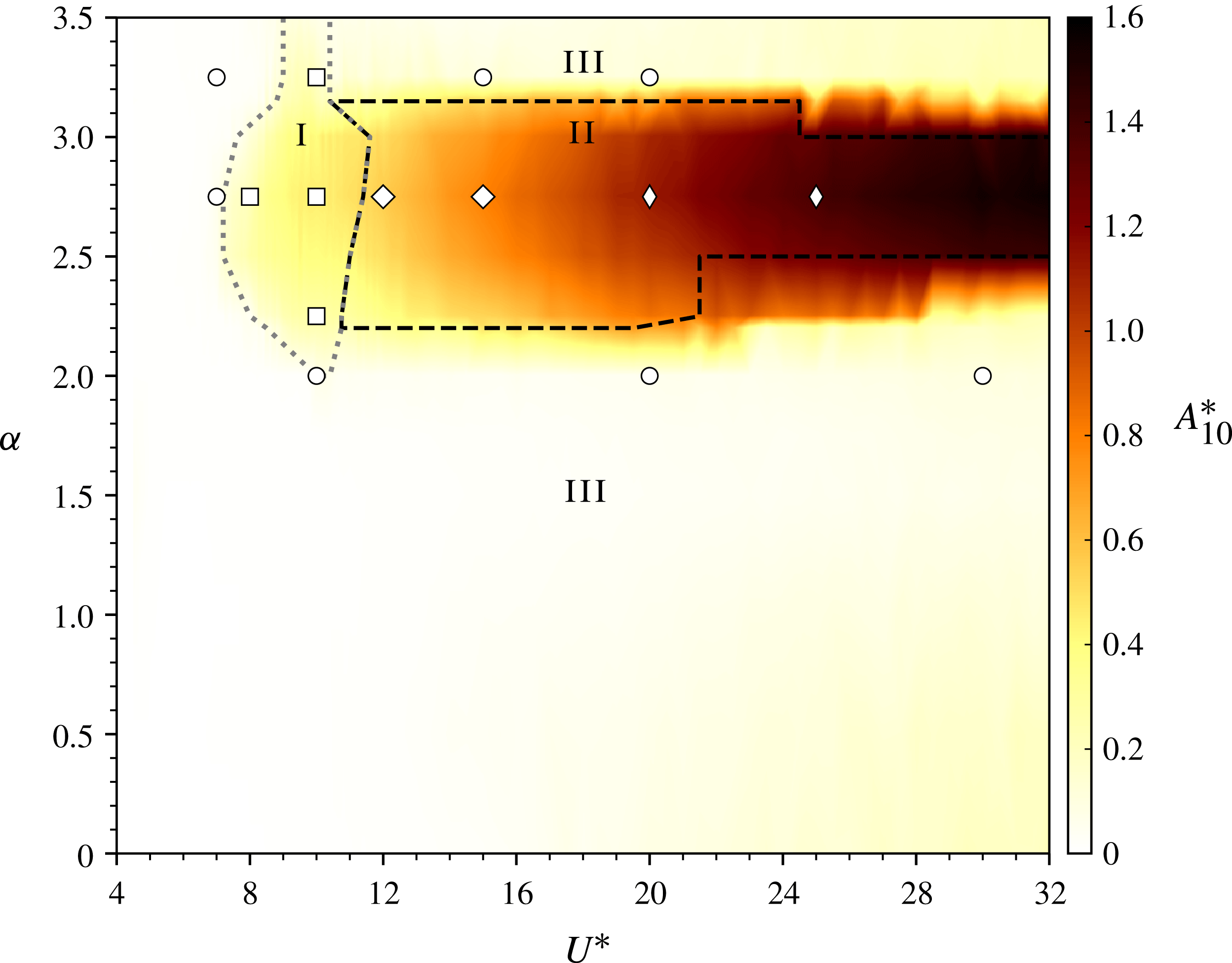
The wake patterns overlaid on a map of amplitude response contours in the
 $U^{\ast }$
–
 $\unicode[STIX]{x1D6FC}$
space. In this space, three vibration regions are categorised: (I) VIV synchronisation region, (II) rotation-induced galloping synchronisation region and (III) desynchronised region. Four wake patterns are identified: ○, CA-I pattern; ▫, A(2S) pattern; ♢; CA-II pattern;
 $\diamondsuit$
, CA-III pattern.

Figure 18 shows a contour map of the
 $A_{10}^{\ast }$
amplitude response in the
 $U^{\ast }{-}\unicode[STIX]{x1D6FC}$
parameter space. In accordance with previously presented results and discussion, there are three vibration regions: (I) VIV synchronisation region (enclosed by the grey dotted line), (II) rotation-induced galloping region (enclosed by the black dashed line) and (III) desynchronised region. The wake patterns observed from PIV measurements are marked with different symbols on this figure. It should be noted that the PIV measurements were conducted with a focus on
 $\unicode[STIX]{x1D6FC}=2.75$
which exhibits largest-scale oscillations to indicate how the wake structure changes as
 $U^{\ast }$
is varied in different vibration regions.
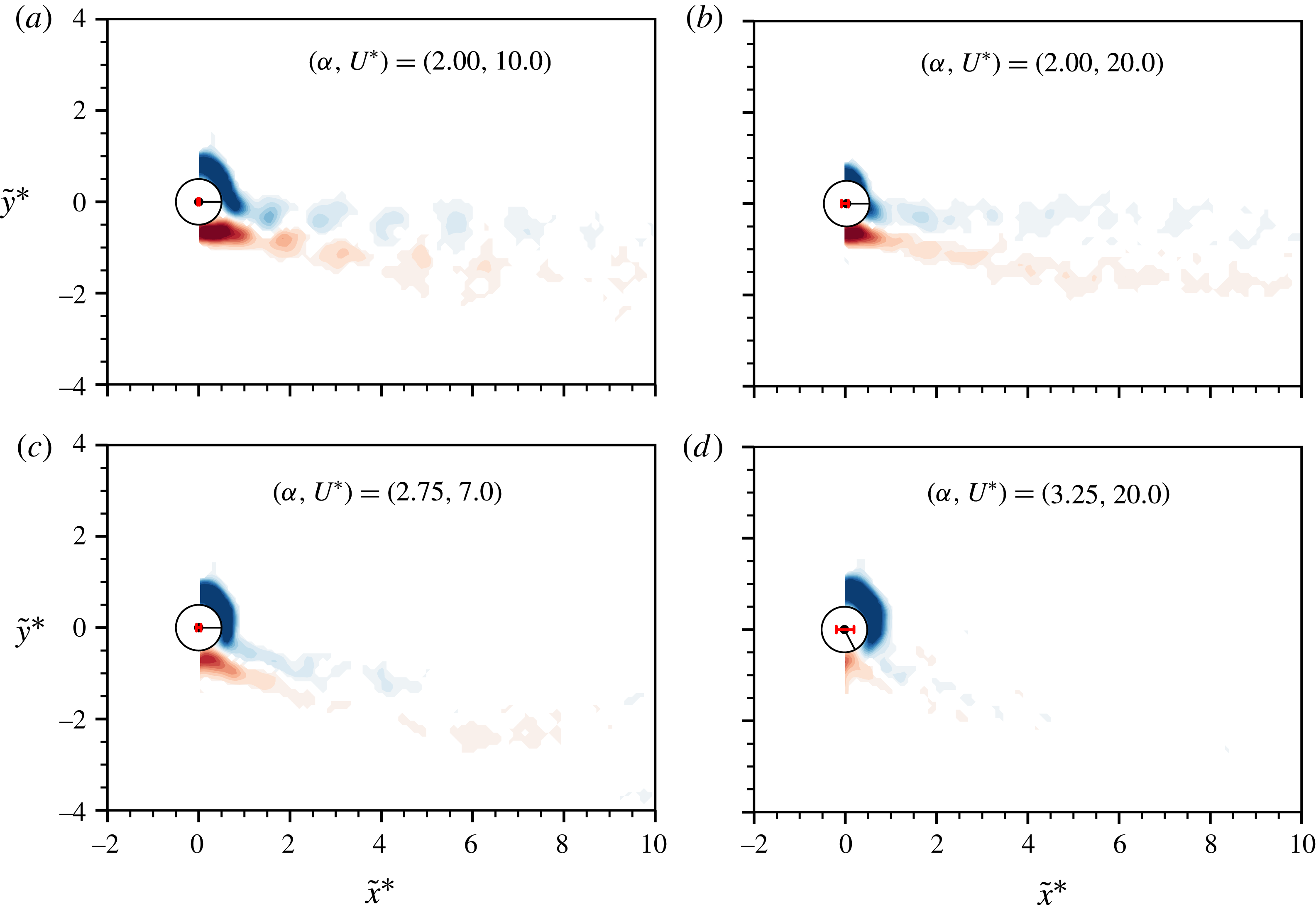
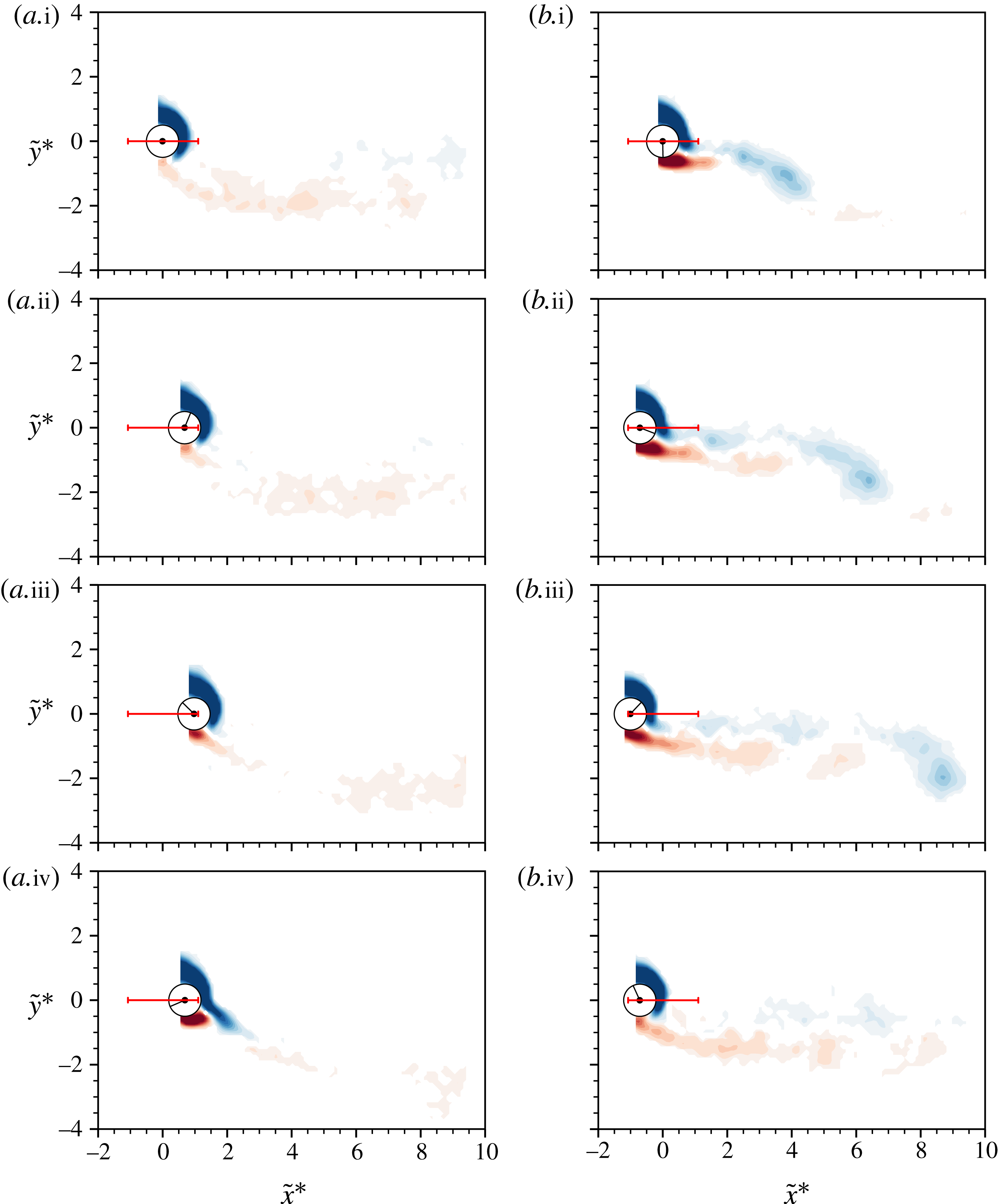
The C(AS) wake pattern observed at different locations in desynchronised regions. It should be noted that
 $\tilde{x}^{\ast }$
denotes the normalised oscillatory component of the cylinder motion, while
 ${\tilde{y}}=0$
. The normalised vorticity range is
 $\unicode[STIX]{x1D714}^{\ast }=\unicode[STIX]{x1D714}D/U\in [-2,2]$
, where
 $\unicode[STIX]{x1D714}$
is the vorticity. In each plot, the horizontal line between two vertical bars in red represents the peak-to-peak vibration amplitude; the black clock indicator represents the angular displacement of the cylinder from its initial position. Supplementary movies 1–4 for the full oscillation cycles are available at https://doi.org/10.1017/jfm.2018.357.

Outside the two synchronisation regions I and II, the cylinder vibration is found to be chaotic with very low but non-negligible amplitudes (
 $A_{10}^{\ast }\lesssim 0.25$
). Spot PIV measurements (marked by open circles) indicate that the wake comprises small asymmetric vortices of opposite sign being shed simultaneously, as shown in figure 19. Thus, the coalescence of these small asymmetric vortices has led to this mode being named CA-I. This wake mode is found to be similar to the C(AS) mode observed in the case of transverse FIV of a rotating cylinder by Wong et al. (Reference Wong, Zhao, Lo Jacono, Thompson and Sheridan2017), noting that the C(AS) mode involves switching behaviour. Moreover, the present CA-I pattern is similar to the S-I mode which was named for the shedding of symmetric small vortices in streamwise VIV of a non-rotating cylinder by Cagney & Balabani (Reference Cagney and Balabani2013a
,Reference Cagney and Balabani
b
), while the primary difference is that the CA-I pattern is deflected by the cylinder rotation. Unlike the C(AS) and S-I modes, the CA-I pattern appears to be stable, with no wake mode switching or competition behaviour observed; however, the size of the shed vortices reduces as
 $U^{\ast }$
or
 $\unicode[STIX]{x1D6FC}$
is increased.
In vibration region I, a dominant wake mode persists across the region, for which VIV synchronisation occurs. Here, the wake structure is identified as the A(2S) pattern, as demonstrated in figure 20. This wake mode is composed of two asymmetric single (S) vortices of opposite sign shed per oscillation cycle, which appears to be a deflected 2S mode due to the effects of cylinder rotation. Such a wake mode is also apparent for similar oscillation amplitudes (
 $A_{10}^{\ast }\lesssim 0.5$
) in the parameter ranges of
 $4\lesssim U^{\ast }\lesssim 5$
and
 $1.5\lesssim \unicode[STIX]{x1D6FC}\lesssim 2.3$
in the study of transverse FIV of a rotating cylinder by Wong et al. (Reference Wong, Zhao, Lo Jacono, Thompson and Sheridan2017). Differently from the case of Wong et al. (Reference Wong, Zhao, Lo Jacono, Thompson and Sheridan2017), where positive (anticlockwise) and negative (clockwise) vortices have similar size and strength, the present measurements show that the negative vortices (in blue) shed from the retreating side of the cylinder are well defined and relatively much stronger, whereas the positive vortices (in red) shed from the advancing side of the cylinder have a prolonged structure and diffuse much earlier than the negative vortices. In general, however, the present A(2S) mode is found to be robustly stable, with both the total and vortex phases consistently at almost zero.
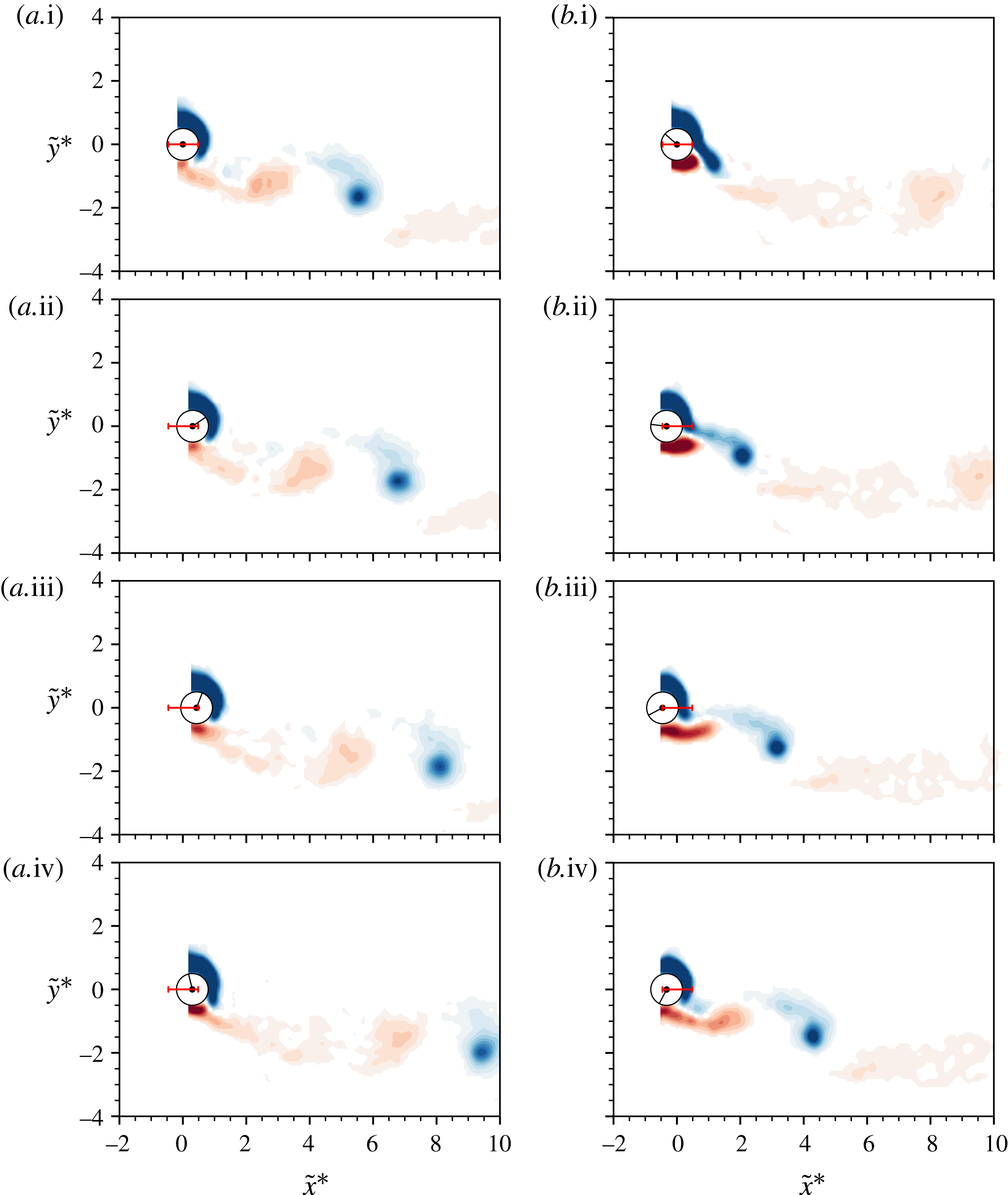
At the early stage of vibration region II, i.e. at
 $(\unicode[STIX]{x1D6FC},U^{\ast })=(2.75,12.0)$
shown in figure 21, the shear layers from the advancing side of the cylinder become noticeably more prolonged, due to increased oscillation amplitudes. During the first half oscillation cycle shown in figure 21(a.i–a.iv), the prolonged positive shear layer interacts with a small negative vortex and breaks, and during the second half oscillation cycle, a relatively stronger negative vortex is formed around the upper side of the cylinder and is cut off by a new forming positive shear layer from the lower side (figure 21
b.iii). Afterwards, another small negative vortex is shed and interacts with the new positive shear layer (figure 21
b.iii). It seems that a number of asymmetric vortices or vortex structures of different sizes are formed during one oscillation cycle. Thus, this coalescence of vortex structures in the wake is named the CA-II mode. As the oscillation amplitudes are further increased at higher reduced velocities, i.e. at
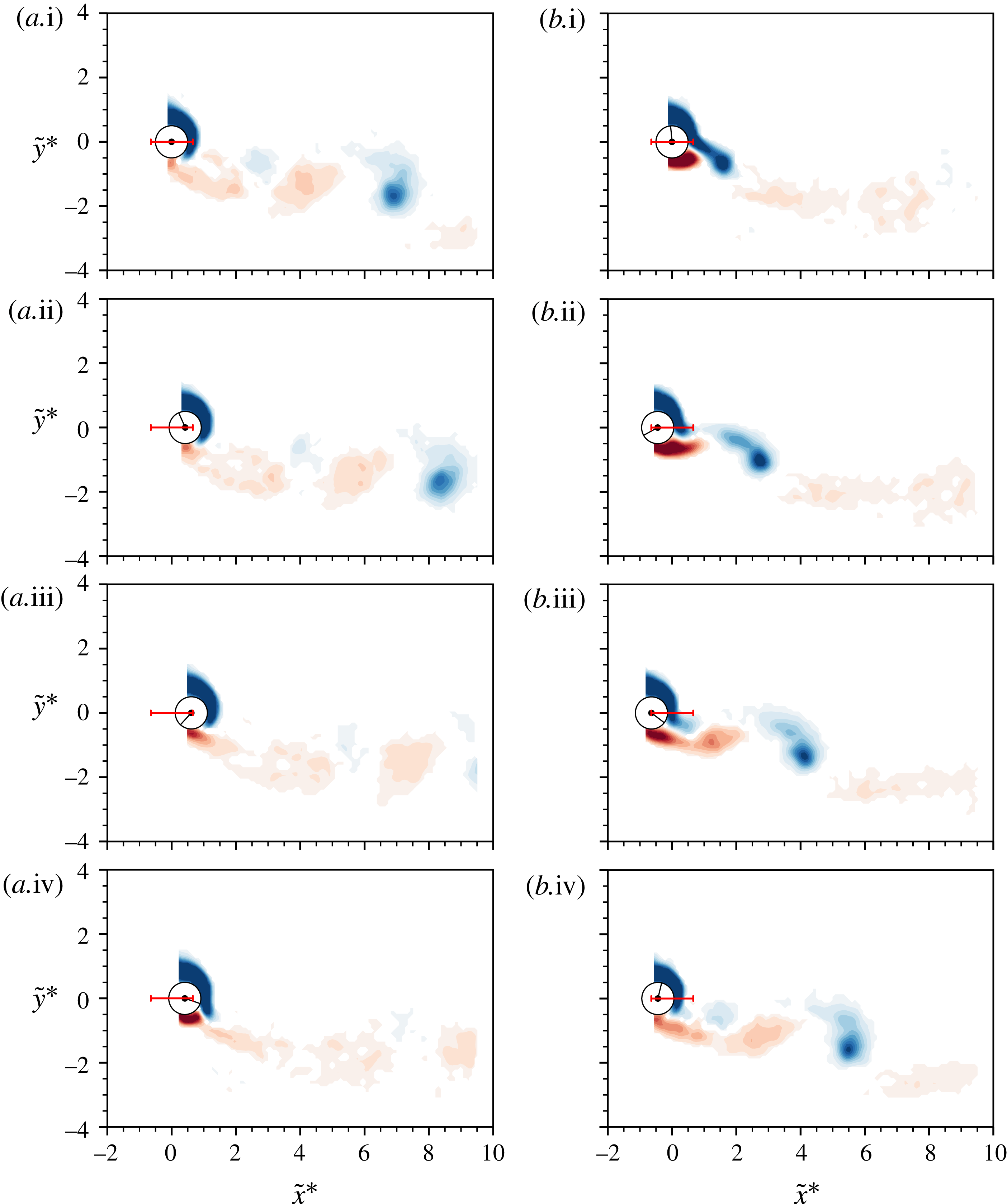
 $(\unicode[STIX]{x1D6FC},U^{\ast })=(2.75,20.0)$
shown in figure 22, the shear layers from both the advancing and the retreating sides of the cylinder become even more prolonged. The vortex-shedding mode seems to be similar to the observed CA-II mode; however, more small vortex structures form when the negative shear layer breaks (figure 22
b.iii). At this point, while
 $\unicode[STIX]{x1D719}_{total}$
remains close to
 $0^{\circ }$
,
 $\unicode[STIX]{x1D719}_{vortex}$
deviates slightly from
 $0^{\circ }$
. Correspondingly, this wake mode is named CA-III. This wake mode is still observed for high velocities that show a greater deviation in
 $\unicode[STIX]{x1D719}_{vortex}$
, i.e.
 $(\unicode[STIX]{x1D6FC},U^{\ast })=(2.75,25.0)$
. These results indicate that the deflected shear layers are affected by the oscillation amplitudes due to increased
 $U^{\ast }$
, and a number of small vortex structures are formed when the shear layers break.
Phase-averaged vorticity contours showing the evolution of the A(2S) wake pattern at
 $(\unicode[STIX]{x1D6FC},U^{\ast })=(2.75,10.0)$
. For further details, see the caption to figure 19. See supplementary movie 5 for the full oscillation cycle.

Phase-averaged vorticity contours showing the evolution of the CA-II wake pattern at
 $(\unicode[STIX]{x1D6FC},U^{\ast })=(2.75,12.0)$
. For further details, see the caption to figure 19. See supplementary movie 6 for the full oscillation cycle.

Phase-averaged vorticity contours showing the evolution of the CA-III wake pattern at
 $(\unicode[STIX]{x1D6FC},U^{\ast })=(2.75,20.0)$
. The normalised vorticity range is
 $\unicode[STIX]{x1D714}^{\ast }\in [-1,1]$
. For further details, see the caption to figure 19. See supplementary movie 7 for the full oscillation cycle.

3.4 Mechanism for rotation-induced galloping oscillations
Bourguet & Lo Jacono (Reference Bourguet and Lo Jacono2015) showed through two-dimensional simulations that at a low Reynolds number of
 $Re=100$
, the quasi-steady theory cannot account for the rotation-induced galloping behaviour observed at high
 $U^{\ast }$
. This was demonstrated through the predicted variation of drag coefficient with cylinder velocity, which has a negative slope. Thus, movement downstream from equilibrium will not result in increased aerodynamic forcing of the cylinder, unlike the situation for (quasi-steady supported) galloping.
Some insight into the physical mechanism responsible for the large oscillations observed in this much-higher-Reynolds-number case can be gained by examining the variation of the mean drag coefficient with the rotation ratio for the rigidly mounted cylinder, given in figure 5(b). This shows that for a rotation rate beyond approximately
 $\unicode[STIX]{x1D6FC}=2$
, the drag coefficient increases with
 $\unicode[STIX]{x1D6FC}$
. Suppose that the cylinder begins to move downstream away from its equilibrium position at a velocity
 $u^{\prime }$
, then the effective oncoming flow velocity seen by the cylinder is reduced from
 $U$
to
 $U-u^{\prime }$
, leading to an effective increased rotation ratio of
 $\unicode[STIX]{x1D6FC}\longrightarrow \unicode[STIX]{x1D6FC}(1+u^{\prime }/U)=\unicode[STIX]{x1D6FC}(1+\unicode[STIX]{x0394}u)$
, with
 $\unicode[STIX]{x0394}u=u^{\prime }/U$
. Locally, the variation of drag can be approximated by
 $\overline{C}_{x}\simeq \overline{C}_{x}(\unicode[STIX]{x1D6FC}_{0})+\unicode[STIX]{x1D6FD}(\unicode[STIX]{x1D6FC}-\unicode[STIX]{x1D6FC}_{0})\simeq {\overline{C}_{x}}_{0}+\unicode[STIX]{x1D6FD}\unicode[STIX]{x1D6FC}\unicode[STIX]{x0394}u$
, where
 $\unicode[STIX]{x1D6FD}$
is the slope of the
 $\unicode[STIX]{x1D6FC}$
–
 $\overline{C}_{x}$
curve. This suggests that downstream motion will increase the quasi-steady force coefficient, enhancing further downstream movement, sustaining the oscillations. The situation is not quite as simple as this, however, because the actual force depends on the effective oncoming flow velocity, which is reduced by downstream motion. The effective force should take this into account also, i.e.
 $F_{x}\propto \overline{C}_{x}U^{2}\longrightarrow \overline{C}_{x}(U-u^{\prime })^{2}\simeq \overline{C}_{x}U^{2}(1-2\unicode[STIX]{x0394}u)$
. Overall, this suggests that the net change to the forcing varies according to
 ${\sim}\unicode[STIX]{x1D6FD}\unicode[STIX]{x1D6FC}\unicode[STIX]{x0394}u-2\unicode[STIX]{x0394}u\overline{C}_{x}=(\unicode[STIX]{x1D6FD}\unicode[STIX]{x1D6FC}-2\overline{C}_{x})\unicode[STIX]{x0394}u$
. Therefore, self-sustained oscillations require
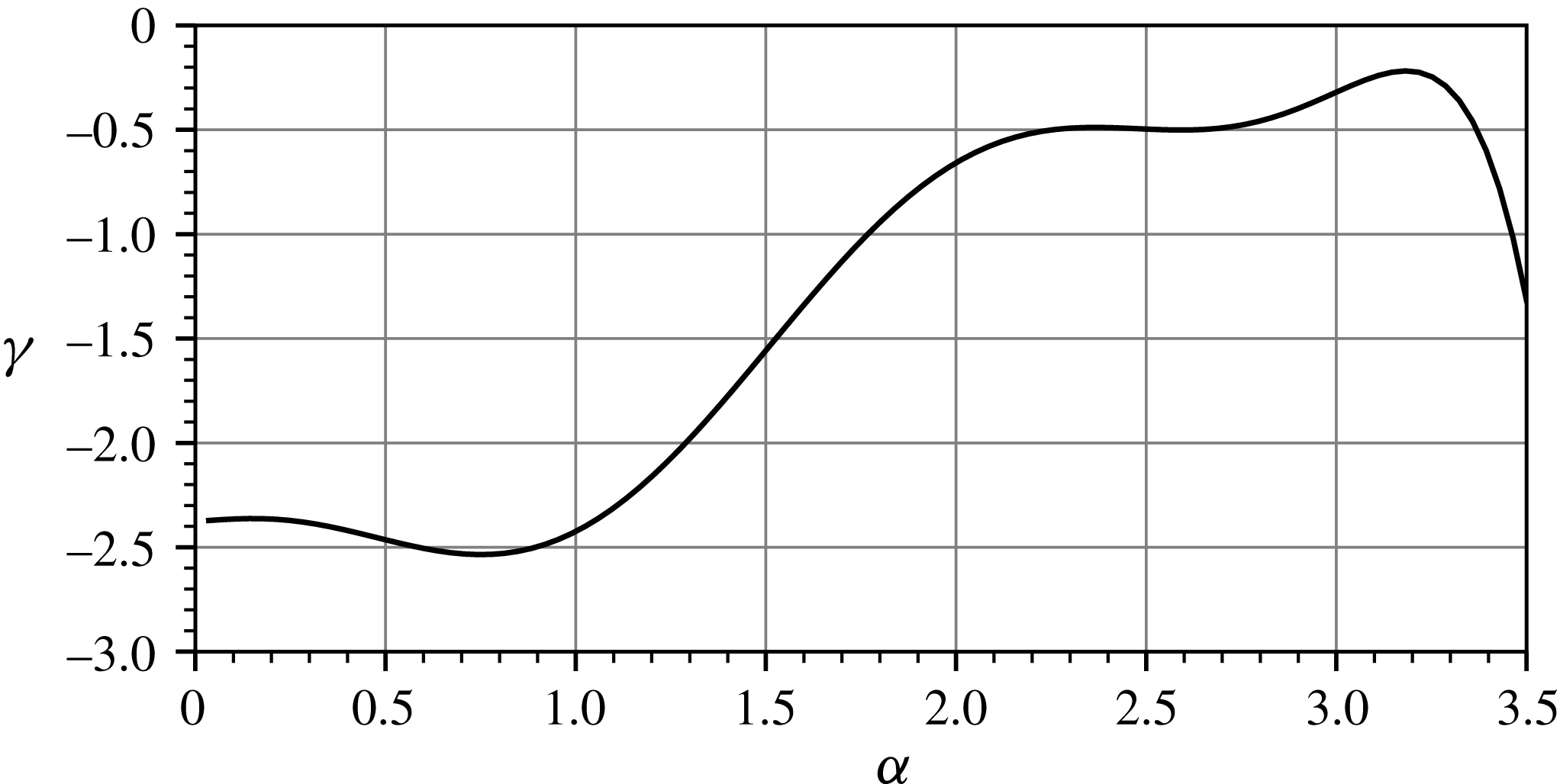
 $\unicode[STIX]{x1D6FE}=(\unicode[STIX]{x1D6FD}\unicode[STIX]{x1D6FC}-2\overline{C}_{x})>0$
, based on quasi-steady theory.
Use of the data from figure 5(b) allows this function
 $\unicode[STIX]{x1D6FE}$
to be plotted as a function of
 $\unicode[STIX]{x1D6FC}$
in figure 23. The simple analysis suggests that self-sustained oscillations will not occur over the range of
 $\unicode[STIX]{x1D6FC}$
examined; however, the function is closer to neutral stability over the range
 $2.20<\unicode[STIX]{x1D6FC}<3.15$
, approximately consistent with the observed range of
 $\unicode[STIX]{x1D6FC}$
leading to large rotation-induced galloping oscillations, as seen in figure 6. It is also interesting that during galloping, the mean drag coefficient variation with the rotation rate is close to that for a non-oscillating rotating cylinder, as seen through a comparison between figures 5(b) and 16(a). This suggests that it should be reasonable to apply quasi-steady theory to try to predict whether oscillations will be sustained. Thus, the quasi-steady theory seems to play an important if incomplete role in the maintenance of the oscillations. The other important factor may be that vortex shedding is suppressed for a rotating cylinder beyond
 $\unicode[STIX]{x1D6FC}\simeq 2$
. This can be interpreted as the rotation suppressing the absolute wake shedding instability. However, at higher rotation rates, the wake is still likely to be convectively unstable. Thus, when the cylinder oscillates in this rotation rate range, shedding should occur at the system oscillation frequency. Figure 21 clearly shows that this is the case, with vortex shedding occurring at the system frequency. The question is then whether the formation and release of vortices during shedding contributes to the aerodynamic forcing to help to maintain the resonance. Indeed, figure 17 suggests that this is the situation. The vortex phase, which is the phase difference between the vortex forcing and the displacement signal, is initially close to zero from the onset of the rotation-induced galloping
 $U^{\ast }$
range for rotation rates corresponding to large oscillations. This means that as the body begins to move downstream, the vortex force also increases, helping to sustain the oscillations. Thus, it appears that the galloping behaviour is assisted by the induced vortex shedding into the wake, suggesting that these oscillations are generated by the combination of quasi-steady forcing together with vortex-induced vibration.
It is perhaps also of interest that it is not clear that the same mechanism directly applies to the low-Reynolds-number case examined by Bourguet & Lo Jacono (Reference Bourguet and Lo Jacono2015). In that case, the mean drag curve does not increase beyond
 $\unicode[STIX]{x1D6FC}=2$
, so quasi-steady theory does not assist in maintaining the resonance.
Variation of
 $\unicode[STIX]{x1D6FE}$
against
 $\unicode[STIX]{x1D6FC}$
. Negative values indicate that the system state is stable against galloping according to the quasi-steady approximation. However, it is clearly closer to neutrally unstable over the range
 $2.20<\unicode[STIX]{x1D6FC}<3.15$
, where large rotation-induced galloping oscillations are observed to occur.

4 Conclusions
The results presented here are the first to characterise experimentally the in-line FIV of a rotating circular cylinder. Careful experiments were conducted extensively over a wide parameter space of
 $5\leqslant U^{\ast }\leqslant 32$
and
 $0\leqslant \unicode[STIX]{x1D6FC}\leqslant 3.5$
, and characteristics, including the vibration response, fluid forces and wake structures, of the fluid–structure system were examined.
There are three observed vibration regions which exhibit VIV synchronisation (vibration region I), rotation-induced galloping (vibration region II) and desynchronised (vibration region III) responses in the parameter space under study. In regions I and II, significantly larger body oscillations were found to be associated with wake–body synchronisation. The present study showed that the peak amplitude can reach up to
 ${\sim}0.5D$
in the VIV synchronisation region and up to
 $1.56D$
in a monotonically and unboundedly increasing trend in the rotation-induced galloping region. In the desynchronised region, on the other hand, cylinder oscillations were chaotic, and the peak amplitude was observed to be
 ${\sim}0.25D$
. These results have shown that cylinder rotation can cause distinctly different vibration responses, with substantially larger amplitudes compared with previous studies of in-line VIV of a non-rotating cylinder which report very small peak oscillation amplitudes (
 ${\lesssim}0.15D$
) in lock-in regions. Furthermore, it was found that significant body vibration occurred within the rotation rate range
 $2.20\lesssim \unicode[STIX]{x1D6FC}\lesssim 3.15$
(depending on
 $U^{\ast }$
). In particular, unboundedly increasing amplitude response with reduced velocity was found for rotation rates
 $2.75\leqslant \unicode[STIX]{x1D6FC}\leqslant 3.00$
. This is significantly different from the previous low-Reynolds-number results that oscillation amplitudes increased with
 $\unicode[STIX]{x1D6FC}$
for a given
 $U^{\ast }$
in the rotation-induced galloping region (the second vibration region).
Force measurements showed that the time-averaged displacement can be well predicted based on the mean drag coefficients of a rigidly mounted rotating cylinder. It was found that the cylinder vibration had little effect on
 $\overline{C}_{x}$
of a rotating cylinder for the range
 $0\leqslant \unicode[STIX]{x1D6FC}\leqslant 1.75$
, in which
 $\overline{C}_{x}$
decreased monotonically to its minimum with increasing
 $\unicode[STIX]{x1D6FC}$
, while minor deficits between the vibrating and non-vibration cases were observed for
 $2.50\leqslant \unicode[STIX]{x1D6FC}\leqslant 3.00$
. In general, on the other hand, the magnitude of
 $\overline{C}_{y}$
(the Magnus force) increased quadratically with
 $\unicode[STIX]{x1D6FC}$
for both the vibrating and non-vibrating cylinders. These results indicate that the cylinder vibration has a subtle effect on the mean fluid forces over the rotation rate range investigated. The peak values of
 $C_{x}^{RMS}$
and
 $C_{y}^{RMS}$
were found to be 0.42 and 1.6, respectively, at
 $U^{\ast }\simeq 9.0$
in the VIV synchronisation region. In the rotation-induced galloping regime,
 $C_{x}^{RMS}$
decreased considerably as
 $U^{\ast }$
was increased, whereas
 $C_{y}^{RMS}$
decreased marginally.
Interestingly, frequency PSD contours showed that harmonic components of
 $f^{\ast }=1$
, 2 and 3 appeared simultaneously in the streamwise and transverse fluid forces when the body oscillation frequency matched the dominant frequency of vortex shedding (or the lift force). This means that the imposed rotation can modulate the frequency of the streamwise fluid force to be synchronised with that of the transverse lift in in-line FIV.
Particle image velocimetry measurements were focused on a fixed rotation rate (
 $\unicode[STIX]{x1D6FC}=2.75$
) across the three vibration regions. Additionally, several adjacent locations outside the VIV synchronisation and rotation-induced galloping regions were examined. It was found that the wake in the adjacent desynchronised region exhibited CA-I patterns, which were composed of a coalescence of small vortices of opposite sign shed simultaneously. Across the VIV synchronisation region, a dominant wake pattern A(2S) was observed, which was composed of two single vortices of opposite sign shed per oscillation cycle that were deflected asymmetrically, across the VIV synchronisation region. At the early stage of the rotation-induced galloping response, a CA-II mode was observed for reduced velocity up to
 $U^{\ast }=15$
. For higher
 $U^{\ast }$
values, a CA-III mode was encountered with substantially large oscillations. It is of great interest that the imposed rotation can cause regular vortex shedding in in-line FIV at rotation rates that see suppression of the BvK vortex shedding in the case of a rigidly mounted cylinder (
 $\unicode[STIX]{x1D6FC}\gtrsim 1.75$
).
As our results demonstrate, the vibration regimes in this study are distinctly different from those of the previous low-Reynolds-number numerical simulations by Bourguet & Lo Jacono (Reference Bourguet and Lo Jacono2015). Thus, it would be of further interest to investigate the effect of Reynolds number on the vibration response in the
 $U^{\ast }$
–
 $\unicode[STIX]{x1D6FC}$
space. It is also of interest to examine whether significant vibration would reoccur beyond
 $\unicode[STIX]{x1D6FC}=3.5$
, as previous studies of rigidly mounted cylinders have indicated that a secondary vortex-shedding regime may occur at high
 $\unicode[STIX]{x1D6FC}$
values.
Acknowledgements
The support from Australian Research Council Discovery Project grants DP150102879 and DP170100275 is gratefully acknowledged.
Supplementary movies
Supplementary movies are available at https://doi.org/10.1017/jfm.2018.357.
Appendix
Figure 24 shows validation tests for the derived body acceleration against the direct measurements of the accelerometer for a non-rotating cylinder experiencing VIV at four different reduced velocities.
Validation test sample time traces of the body acceleration derived from the linear encoder against the measurements using the accelerometer for four different reduced velocities associated with transverse VIV of a non-rotating cylinder: (a)
 $U^{\ast }=4.50$
(initial branch), (b)
 $U^{\ast }=5.6$
(upper branch), (c)
 $U^{\ast }=6.5$
(lower branch) and (d)
 $U^{\ast }=8.0$
(lower branch). It should be noted that the upper subplots show time traces of the body displacement and the lower subplots show the derived body acceleration (black dot-dashed line) against the measured value (blue solid line). Clearly, the derived values match the direct measurements.