I. INTRODUCTION
The newest speedy progress in wireless applications and the increasing demands of handy electronic instruments have significantly enlarged the requests for wireless power transfer (WPT) due to the growing demand of wireless applications like portable electronic devices, biomedical implants, and wireless buried sensors. WPT or wireless electricity (WiTricity) can be defined as the transmission of electrical power from a power source to one or more electrical loads without the essential for current-carrying cables [Reference Choadhary, Singh, Kumar and Prashar1]. WPT can afford power from an AC source to compatible batteries or devices without physical connectors or cords. WPT can be used for recharging mobile phones, tablets, drones, cars, conveyance equipment, wireless sensors, and biomedical applications [Reference Das Barman, Reza, Kumar, Karim and Munir2–Reference Kibret, Teshome and Lai4]. WPT can be implemented by different methods that employ time-varying electric/magnetic (near-field) or electromagnetic (EM) (far-field) fields. Besides, the near-field WPT is non-radiative, safe for health, and efficient for short- and mid-range applications.
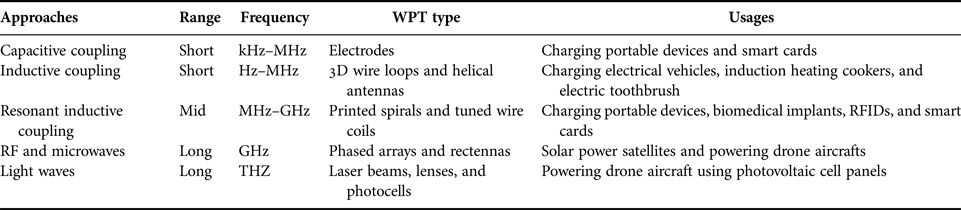
The coupling for the non-radiative short distance WPT is achieved through inductive or capacitive elements [Reference Hirayama, Amano, Kikuma and Sakakibara5]. However, the resonant inductive coupling is used for intermediate range WPT systems [Reference Jolani, Yu and Chen6]. The inductive coupling technique is considered the best method for realizing efficient WPT systems and is generally used for designing low-frequency WPT systems. For high-frequency WPT systems, the resonant elements are considered the appropriate selection for designing these systems. Resonant elements concentrate the power at the operating frequency band of these structures. Consequently, the power transmission efficiency can be enhanced. Furthermore, WPT systems with strong resonant coupling employ intermediate resonators with a high-quality factor to increase the transmission efficiency [Reference Hekal, Abdel-Rahman, Jia, Allam, Barakat and Pokharel7]. Table 1 sums up different WPT techniques using the near-field coupling and the far-field radiative approaches [Reference Das Barman, Reza, Kumar, Karim and Munir2, Reference Abidin, Khalifa, Elsheikh and Abdulla3, Reference Jolani, Yu and Chen6]. Many of the recently published articles in the field of magnetic resonant coupling (MRC) for WPT employs three-dimensional (3D) round wire loop, spiral loops [Reference Jolani, Yu and Chen8, Reference Jonah, Merwaday, Georgakopoulos and Tentzeris9], or antennas [Reference Hirayama, Amano, Kikuma and Sakakibara5, Reference Liou, Lin, Tai and Mao10]. These loops are frequently bulky in structure and require accurate fabrication to keep high-quality factor. Further, they produce practical problems for the WPT systems to be realized in compact electronic devices and biomedical implants [Reference Kibret, Teshome and Lai4]. Although these systems have good quality factors, they have some disadvantages such as design complexity and limitations of the transmission distance.
Comparisons of different WPT techniques.

Defected ground structures (DGSs) with lumped components have been recommended for radio frequency (RF) applications to design band-pass and band-stop filters with low profiles [Reference Hekal, Abdel-Rahman, Jia, Allam, Barakat and Pokharel7]. The main advantage of a DGS WPT system is the feeding topology, where the power is transferred from/to the main transmitter/receiver (TX/RX) resonators by electrical coupling and the external quality factor can be easily optimized. Besides, there are no limitations exist on the optimization of the DGS resonator parameters to achieve maximum power transfer efficiency, unlike the conventional inductive feeding. In [Reference Hekal and Abdel-Rahman11], an H-shaped DGS WPT system is proposed and operated at a frequency of 1 GHz at a distance of 5 mm with an efficiency of 85%. Besides, the RX or the TX size is 25 mm × 25 mm. In [Reference Hekal, Abdel-Rahman, Jia, Allam, Barakat and Pokharel7], two different shapes of DGS are investigated for compact WPT at 0.3 GHz. The H-shaped WPT design has a size of 20 mm × 20 mm and an efficiency of 68% at a transmission distance of 13 mm. While the semi-H-shaped WPT design achieves an improved efficiency of 73% at a separation distance of 25 mm and the total size of the resonator is 21 mm × 21 mm. In [Reference Donelli, Rocca and Viani12], a WPT system based on rectenna array of 12 rectangular patches is proposed at 3.4 GHz with an efficiency of 63% and a large transmission distance. Moreover, a strongly coupled magnetic resonance planar aluminum inductor coil at a high-frequency band of 5.8 GHz is investigated for potential micrometer-scale biosensor applications in [Reference Lie, Nukala, Tsay, Lopez and Nguyen13].
In this research, a novel compact and efficient coupled resonators WPT system having a proper transmission separation is presented for short-range applications. Section II presents the configuration of the utilized half-ring resonators (HRRs) DGS band-stop filter and the modified version, the design and the arrangement of the coupled resonators, and the optimized WPT system. Moreover, the suggested structure using HRRs-DGS is discussed and analyzed. In Section III, the performance of the prototype system is measured and compared with simulated data for confirmations. Finally, Section IV sums up the achieved results of the proposed work with conclusions.
II. SYSTEM DESIGN AND CONFIGURATION
A) The proposed modified ring resonator (MRR)-DGS band-stop filter design
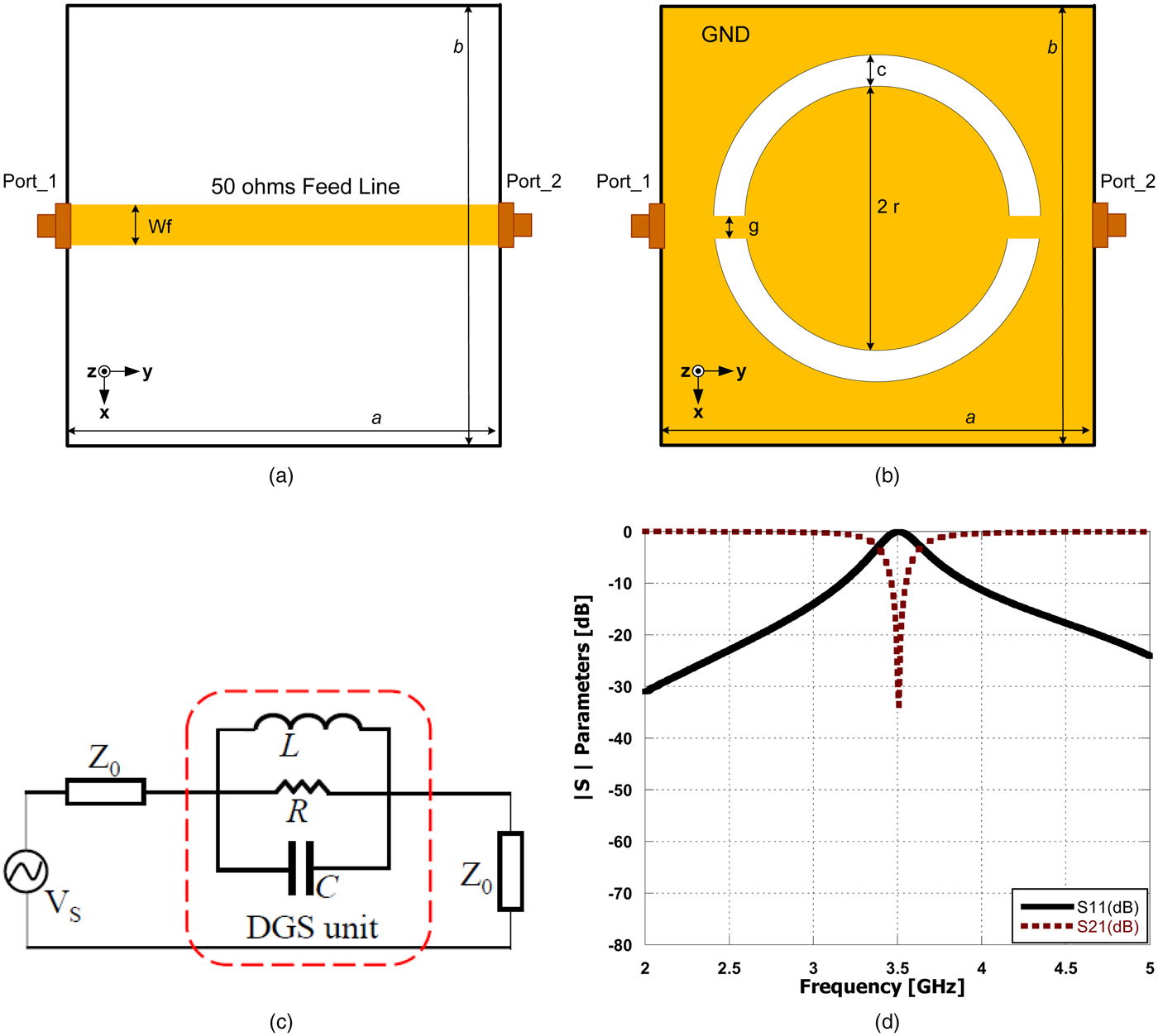
The geometry of the proposed MRR-DGS is depicted in Fig. 1. The filter is constructed on the RT/Duroid 3003 substrate with a thickness of t = 0.762 mm, a dielectric constant ε r of 3, and a loss tangent tan δ of 0.00013. The ring unit is etched in the ground plane and the signal microstrip line has a 1.9 mm width to achieve a 50 Ω characteristic impedance. The dimensions of the etched MRR-DGS are c = g = 1.2 mm and r = 9.5 mm. The filter has an overall size of a = 25 mm × b = 25 mm. Figure 1(c) shows the S-parameters of the MRR-DGS filter. The presented filter is optimized through simulations using a commercial 3D full-wave analysis software package computer simulation technology (CST). The filter is designed to operate at 3.5 GHz of the S-band microwave frequency region. The S-parameters of the proposed MRR-DGS are corresponding to single pole band-stop filter operating at 3.5 GHz and the equivalent circuit of the model is extracted as a tank circuit as displayed in Figs 1(c) and 1(d).
The proposed MRR-DGS band-stop filter. (a) Top layer. (b) Bottom layer. (c) Equivalent circuit model of the filter. (d) S-parameters.

The results of the S-parameters (dB) versus the frequency (GHz) of the proposed MRR-DGS show relatively wide stop-band characteristics and high rejection level at the transmission zero frequency of 3.5 GHz. The stop bandwidth of the MRR-DGS filter is approximately 300 MHz from 3.35 to 3.65 MHz and it has a suitable quality factor around 12 at the cut-off frequency of 3.5 GHz with a high selectivity characteristics.
B) The proposed compact HRR-DGS band-stop filter design
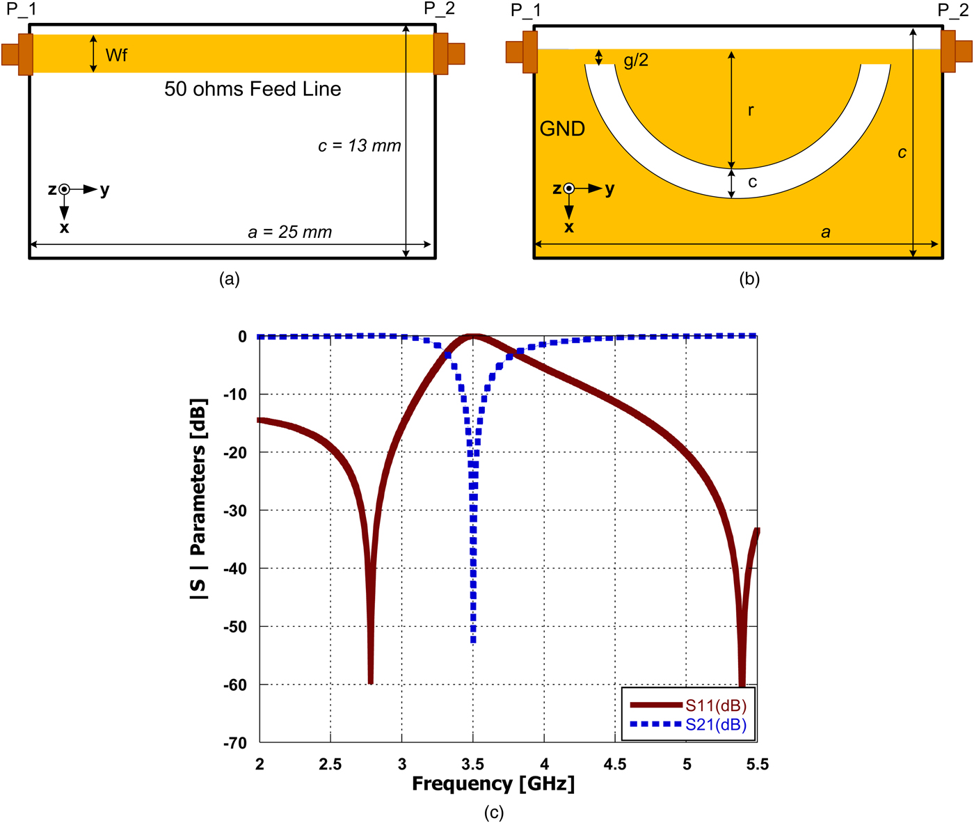
The geometry of the proposed HRR-DGS is shown in Figs 2(a) and 2(b). The filter is construed from the proposed MRR-DGS that has been previously discussed in the prior section and is successfully reduced to half size for compactness and miniaturization with the same dimensions of the etched HRR-DGS. Figure 1(c) shows the S-parameters of the HRR-DGS filter. The filter is designed to operate at a center frequency of 3.5 GHz at the S-band microwave frequency region. The filter has an overall reduced size of a = 25 mm × c = 13 mm. The results of the proposed HRR-DGS show quite wide stop-band characteristics with a high-rejection level at 3.5 GHz. The stop bandwidth of the above HRR-DGS filter is approximately 500 MHz from 3.3 to 3.8 GHz and it has a suitable quality factor of 7 at the cut-off frequency of 3.5 GHz which can be used for designing WPT systems. When two HRRs-DGS are coupled back-to-back, it transfers to a band-pass filter leading to compact and highly efficient WPT system as will be explained in details in the next section.
The proposed compact HRR-DGS band-stop filter. (a) Top layer. (b) Bottom layer. (c) S-parameters.

C) The proposed compact HRR-DGS WPT system design
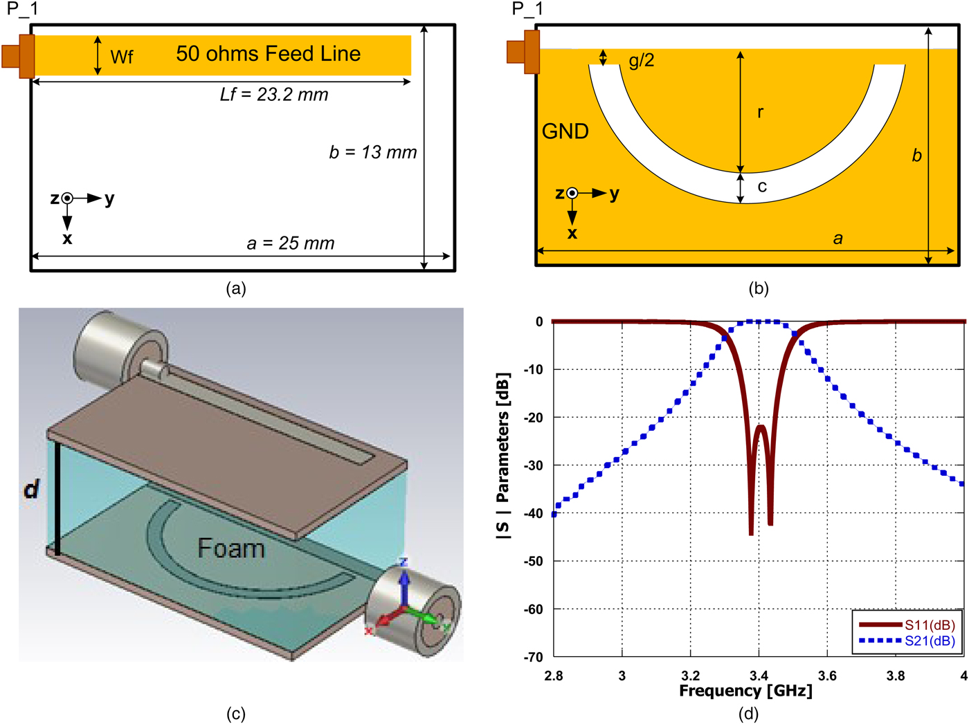
In the following section, the description of the S-band WPT system operating at a center frequency of 3.4 GHz will be detailed. The performance of two coupled HRR-DGS is investigated. The TX and RX are constructed from the HRR-DGS band-stop filter that was designed in the previous section. The used HRR-DGS is shown in Figs 3(a) and 3(b) after optimizing the length of the feed line for good impedance matching between the two coupled resonators at the operating frequency of 3.4 GHz.
The proposed HRR-DGS WPT system and the S-parameters. (a) Top layer. (b) Bottom layer. (c) Implementation of the system on the EM simulator. (d) S-parameters.

The fundamental resonance frequency of the proposed WPT system (f wpt) can be calculated using
 $$f_{wpt} = \displaystyle{c \over {2\pi \; r\sqrt {\varepsilon _{eff}}}}, $$
where c is the velocity of the light in free space and ε eff is the effective dielectric constant. It is noticed that the circumference of the ring resonator DGS (2πr) equals to a guided wavelength at the fundamental resonance frequency as explained in [Reference Atallah, Yoshitomi, Abdel-Rahman and Pokharel14].
A separation (d) is spaced between the two HRRs-DGS as displayed in Fig. 3(c). The medium between the two HRRs-DGS is filled with foam in the simulation part with a permittivity ε r equals 1.04 for good realization of the system. To alter the operating frequency and the matching, the feed line length is adjusted for good matching as shown in Fig. 3(a). Figure 3(d) shows the optimized S-parameters of the proposed HRRs-DGS WPT system which is suitable for charging electronic devices such as wireless sensor nodes working at 3.4 GHz instead of using far-field techniques by employing large size antenna array as investigated in [Reference Donelli, Rocca and Viani12] or as an alternative source using near-field WPT technique.
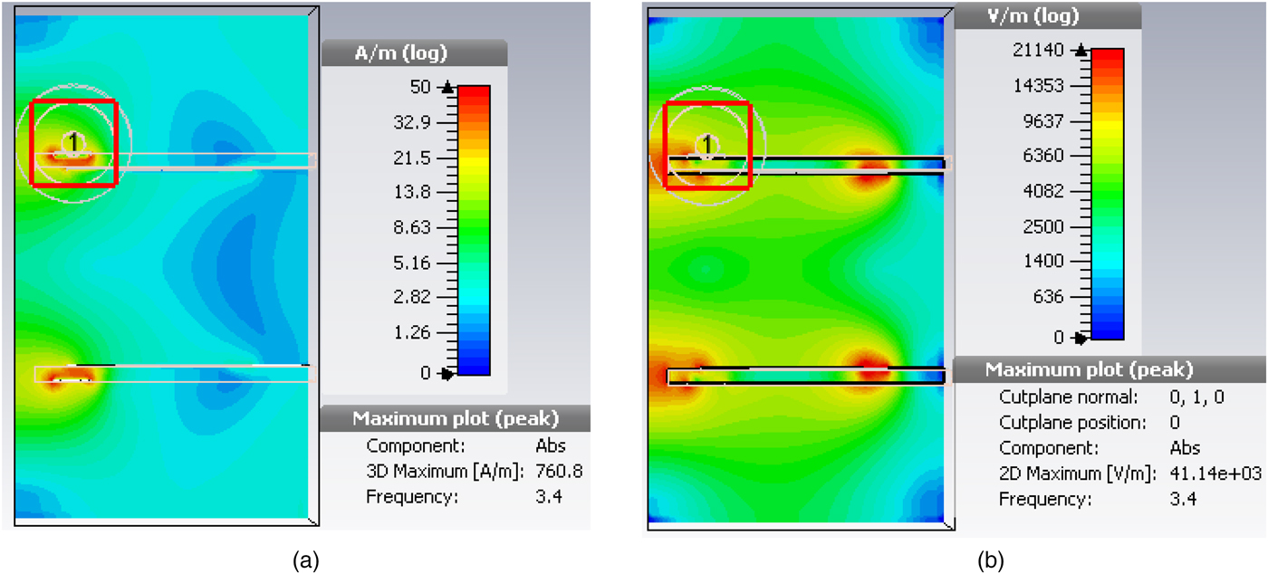
For more investigation of the performance of the proposed design, Fig. 4 shows the magnetic and electric field distributions of the proposed HRR-DGS WPT system (peak amplitude at plane y = 0) that are responsible for the coupling between the driver and the load resonators.
Magnetic and electric field distributions of the proposed HRR-DGS WPT system (peak amplitude at plane y = 0). (a) Magnetic field. (b) Electric field.

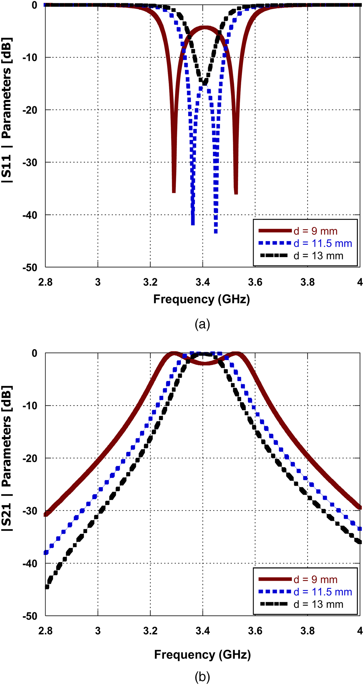
In this part, the influences of the separation distance (d) between the coupled HRRs-DGS on the S-parameters and the overall performance of the system are studied and discussed. By varying the transmission distance (d) between the TX and the RX, the coupling coefficient (K) varies from high values at short distances where the mutual coupling is strong to low values at long distances where the mutual coupling is weak as presented in Fig. 5. At short distances, the coupling is strong enough to make each HRR-DGS resonator affects the other one and the splitting of the resonant frequency occurs such that the two peaks appear around the central frequency f c. These two peaks are called electric and magnetic wall frequencies and designated with f e and f m, respectively. This phenomenon of splitting has been studied in more details in [Reference Hekal and Abdel-Rahman11, Reference Hong and Lancaster15, Reference Zhang, Zhao and Chen16]. The coupling coefficient (K) can be defined as follows [Reference Hong and Lancaster15]:
 $$K = \displaystyle{{f_e^2 - f_m^2} \over {f_e^2 + f_m^2}}. $$
Transmission distance studies of the HRRs-DGS WPT system. (a) |S 11| parameters. (b) |S 21| parameters.

III. EXPERIMENTAL RESULTS
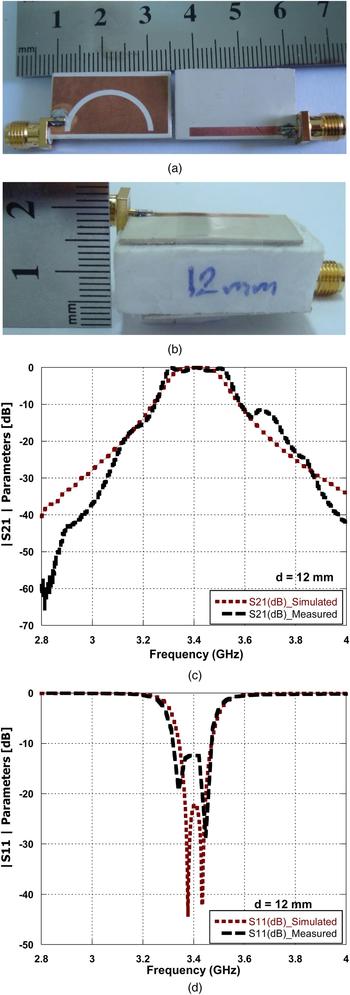
The proposed system was fabricated and tested for verifications. The fabrication of the system was done by a photolithographic method and the layers of the fabricated prototype are shown in Fig. 6(a). Figure 6(b) shows the configuration of the HRRs-DGS WPT system at a separation distance of 12 mm. The gap is filled with a piece of foam as a pillar for fixing and protecting the two resonators in order to achieve accurate measurements. The measurement and the simulation results of the fabricated design are shown in Figs 6(c) and 6(d). The measured |S 21| equals −0.26 dB and the measured |S 11| equals −13 dB at the center frequency of 3.4 GHz and a separation distance of 12 mm between the TX and the RX which is filled with a portion of foam. Moreover, it is obvious that both the simulated and the measured results are close to each other. The efficiency of the WPT system can be obtained by equation (3):
 $$\eta _{wpt} = \vert S_{21} \vert ^2\; \sqrt {(1 - {\vert {S_{11}} \vert } ^2)(1 - {\vert {S_{22}} \vert } ^2)}. $$
The fabricated HRRs-DGS WPT system and the experimental measurements. (a) Top and bottom views. (b) Design setting at a separation distance of 12 mm. (c) Comparisons of simulated and measured |S 21| parameters. (d) Comparisons of simulated and measured |S 11| parameters.

The proposed WPT design achieves improved efficiency of 94% at the center frequency of 3.4 GHz. Furthermore, the WPT design achieves the highest efficiency of 97% at the operating frequency of 3.44 GHz through the separation space of 12 mm. The figure-of-merit (FoM) can be calculated using equation (4) as described in [Reference Hekal and Abdel-Rahman11] which is used for comparing the performances of the WPT systems. The FoM of the proposed WPT structure can be calculated using equation (4) as it was done in [Reference Atallah17] as a presented summary of this extended work:
 $${\rm FoM} = \displaystyle{{(\eta \times d)} \over {{\lpar {L_{sub} \times W_{sub}} \rpar }^{0.5}}}.$$
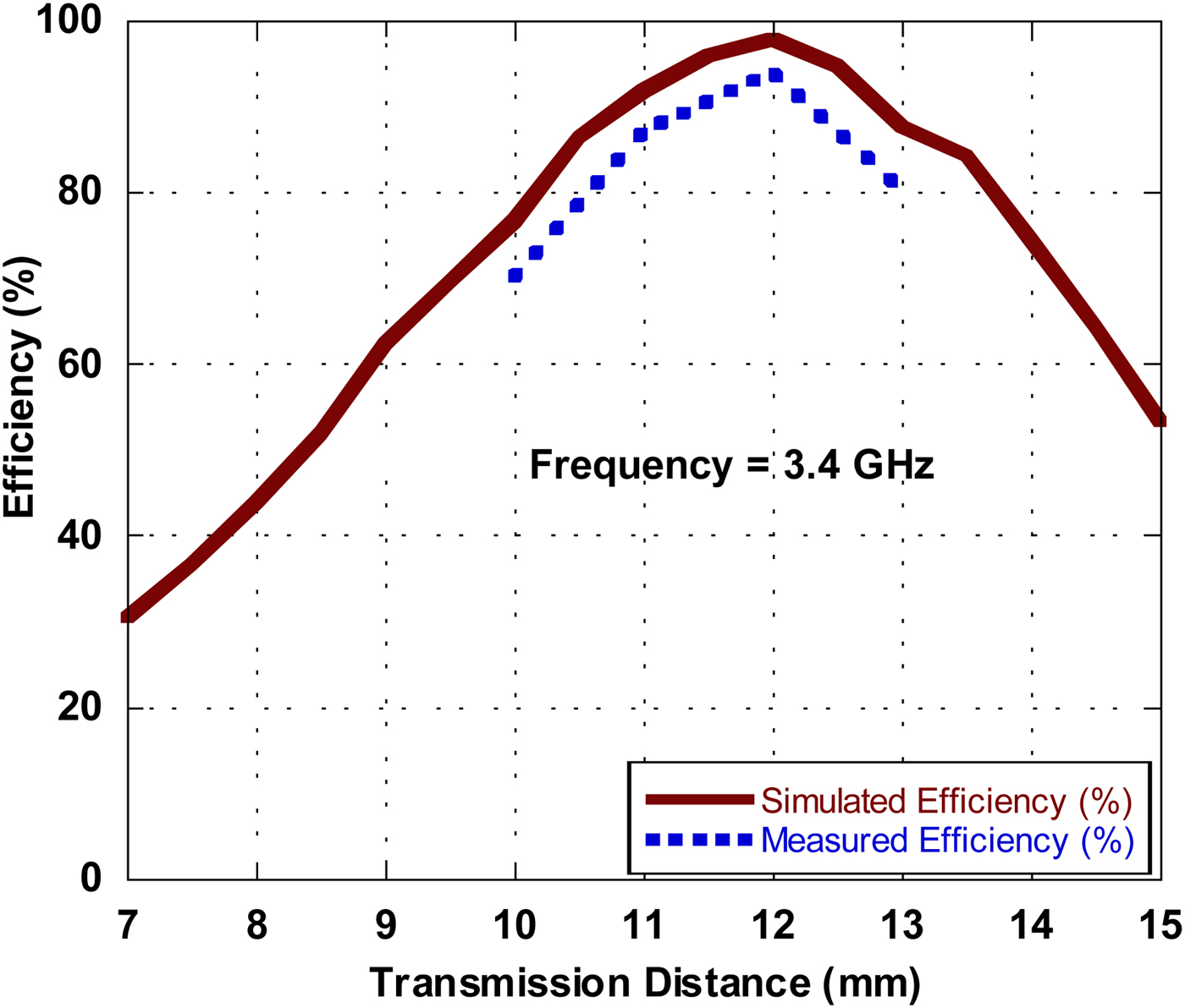
Figure 7 depicts the simulated and the measured WPT efficiencies of the two coupled resonators at the operating frequency of 3.4 GHz and at different transmission distances versus frequency to show the performance and the peak efficiency of the system. Figure 7 shows that the system attains simulated and measured efficiencies of 97 and 94%, respectively, at a separation distance of 12 mm. Slight and tolerable differences between the simulated and the measured efficiencies are found due to the coaxial cables, the feed line connectors, soldering, and fabrication effects.
The simulated and the measured WPT efficiencies versus transmission distance (d) for the proposed coupled resonators at 3.4 GHz.

The performance of the proposed HRRs-DGS WPT system is summarized and compared with other lately proposed WPT structures as presented in Table 2. The proposed system shows a good sizing and an improved efficiency at the operating frequency of 3.4 GHz. Moreover, the proposed coupled resonator system does not employ lumped elements (like SMD capacitors) in the design compared with the literature in Table 2 to reduce the power dissipation and increase the transmission efficiency. Consequently, the proposed design provides higher efficiency than the other designs. However, it has relatively large dimensions as there is no use of lumped capacitors in the proposed configuration to miniaturize the size. The obtained experimental results are quite promising and demonstrating the capabilities of the proposed WPT system as an alternative wireless power supply source for powering electronic devices like buried sensors [Reference Donelli, Rocca and Viani12].
Evaluation of the fabricated HRRs-DGS WPT system compared with other systems.

IV. CONCLUSION
In this work, a novel efficient WPT system with a compact size for short distance applications is proposed, discussed, and fabricated. The system consists of TX and RX which are designed using HRRs-DGS. The system transmits the power at a separation distance of 12 mm and an improved measured efficiency of 94% at 3.4 GHz via EM resonant coupling. The measured performance of the fabricated WPT system is in good agreement with the simulations. The proposed system is suitable for powering electronic appliances and devices such as wireless sensor nodes or as an alternative source for some far field applications.
 Hany A. Atallah was born in Qena, Egypt in 1984. He received his B.Sc. and M.Sc. in Electrical Engineering, Electronics and Communications from South Valley University, Egypt, in 2007 and 2012, respectively. He received his Ph.D. degree in antennas and microwave engineering at Egypt–Japan University for Science and Technology (E-JUST). He is currently working as an assistant professor at Electrical Engineering Department, Qena Faculty of Engineering, South Valley University. He was a Visiting Researcher with the E-JUST Lab, School of Information Science and Electrical Engineering, Kyushu University, Japan, from September 2015 to July 2016. He is a reviewer for Applied Computational Electromagnetics Society (ACES), Advanced Electromagnetics (AEM), and Progress in Electromagnetics Research (PIER) journals. His research interests include antenna design, dielectric resonators, metamaterials, tunable filters, reconfigurable antennas, antenna arrays, microwave filters, and FDTD. His recent research has been on cognitive radio (CR) antennas, wireless power transfer (WPT) for biomedical implants, electric vehicles, and electronic devices, breast cancer detection, smart meters, and the internet of things (IoT).