Introduction
The vast and continuing reduction in the size and power consumption of sensors and complementary metal oxide semiconductor (CMOS) circuitry has led to a focused research effort on onboard power sources that can replace batteries. The concern with batteries has been that they must be charged before use. Similarly, sensors and data acquisition components in distributed networks require centralized energy sources for their operation. In applications such as sensors for structural health monitoring in remote locations, geographically inaccessible temperature or humidity sensors and battery charging or replacement operations can be tedious and expensive. The need to replace batteries in a large-scale sensor network can be problematic and costly and is nearly impossible in hazardous, harsh, and large terrain deployment. An example would be embedded sensor networks in urban battlefields. Logically, the emphasis in such cases has been on developing on-site generators that can transform any available form of energy at that location into electrical energy.Reference Priya and Inman1 Recent advances in low-power very large-scale integration design have enabled ultrasmall power integrated circuits, which can run with only tens of nW to hundreds of μW of power.Reference Chandrakasan, Amirtharajah, Goodman and Rabiner2 This scaling trend has opened the door for on-chip energy harvesting solutions, eliminating the need for chemical batteries or complex wiring for microsensors, thus forming the foundation for battery-less autonomous sensors and network systems.
An alternative to conventional batteries as the power supply is to make use of the parasitic energy available locally in the environment. Unused energy is produced by industrial machines, human activity, vehicles, structures, and environment sources, which could be excellent sources for capturing small amounts of power without affecting the source itself. In recent years, several energy harvesting approaches have been proposed using solar, thermoelectric, electromagnetic, piezoelectric, and capacitive schemes at the meso-, micro-, and nanoscales.Reference Priya and Inman1, Reference Beeby, Tudor and White3, Reference Wang and Song4 These can be simply classified into two categories: (1) energy harvesting for sensor and communication networks using a microelectromechanical systems (MEMS)/thin-film approach, and (2) energy harvesting for other electronic devices using bulk devices. This article mainly focuses on small-scale power energy harvesting techniques (∼1–100 μW) using the MEMS/thin-film approach for the self-supported operation of portable or embedded microdevices and systems. Further, we focus on mechanical vibration energy as the prime source for generating electric power since it is abundant and has an infinite life time.
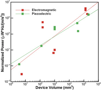
The question one might ask at this stage is: “What is the best mechanism for converting mechanical energy into electrical energy at ∼mm3 dimensions?” There are several mechanisms that can be utilized to convert vibration mechanical energy into electrical energy, including electromagnetic, piezoelectric, magnetoelectric, dielectric elastomers, and electrets. Marin et al. have studied the scaling of output power as a function of effective material volume (v) for different mechanisms.Reference Marin, Bressers and Priya5 By taking into account constitutive equations for the respective conversion mechanisms, the output power of the electromagnetic mechanism is proportional to v 2, while that of the piezoelectric mechanism is proportional to v ¾. Thus, at smaller scales, the piezoelectric mechanism becomes more attractive as compared to electromagnetics. To obtain an approximation of the critical size where piezoelectricity becomes more useful, Figure 1 plots harvester volume versus normalized output power (normalized by acceleration and multiplied by frequency) for various piezoelectric and electromagnetic prototypes reported in the literature.Reference Marin, Bressers and Priya5 From Figure 1, it can be determined that the critical size is in the vicinity of ∼0.5 cm3. At a smaller device volume than this critical size, the electromagnetic transformation factor (similar to electromechanical coupling in piezoelectrics)
 $$\Phi _{\rm{T}} \cong \sum {B\left( {y_{\rm{c}} ,z_{\rm{c}} } \right)} \left( {\Delta L_{{\rm{coil}}} } \right)\cos \left( {{\rm{\theta }}\left( {y_{\rm{c}} ,z_{\rm{c}} } \right)} \right)\Phi \left( {y_{\rm{b}} } \right)$$
Output power as a function of effective material volume for piezoelectric and electromagnetic vibration energy harvesting mechanisms. Variation of output power normalized by acceleration and multiplied by frequency as a function of device volume for various energy harvesters found in literature and commercially.Reference Marin, Bressers and Priya5 The red and green lines are the linear fit to the data. This figure shows that below ∼0.5 cm3, the piezoelectric mechanism has an advantage over electromagnetic mechanism.

reduces sharply with a decrease in magnitude of induction and length of the coil. Here B represents the magnetic field, L is the length of the coil, θ is the angle between  $\vec z \times \vec B$ and the differential conductor length
 $d\vec l$, y c and z c are coordinates in the plane of the coil, and y b is the coordinate on the beam. The transformation factor directly couples the input mechanical energy to the output electrical energy. A reasonable assumption for four-bar electromagnetic energy harvesters is that coil velocity (dz/dt) is orthogonal to the magnetic field vector B given the close proximity of magnets and coil. In order to estimate the voltage, the expression in Equation 1 is integrated over the length of the coil. Thus, dl is the integral variable. Another major problem with inductive harvesters at small scales is their low output voltage, which makes it difficult to use rectification and ac/dc conversion circuits.Reference Bono, Sliski, Huang and O’Handley6 In addition to the normalized power and output voltage, assembly at this scale critically affects the cost of the system. Below the critical volume, assembly of the conductive coil and magnetic layer becomes challenging since monolithic MEMS fabrication is not readily available at the present time. The mechanisms at this scale can be cost-effective if they can be fabricated by monolithic MEMS processes without substantial post-assembly efforts. Thus, for MEMS-scale energy harvesters smaller than ∼0.5 cm3, piezoelectric transduction is the most appropriate scenario since standard MEMS processes are available for many piezoelectric materials. Electrostatic harvesters need separate voltage sources and are relatively bulkier than piezoelectric harvesters at the same power output.Reference Krulevitch, Lee, Ramsey, Trevino, Hamilton and Northrup7 Most importantly, piezoelectric harvesters can directly convert mechanical energy into electrical energy and can be directly integrated into monolithic MEMS-scale systems.Reference Beeby, Tudor and White3, Reference Muralt, Polcawich and Trolier-McKinstry8–Reference Morimoto, Kanno, Wasa and Kotera13
Another question often posed is, “How can one achieve self-powering when the power required is much larger than what can be achieved by MEMS-scale piezoelectric harvesters?” Most reported piezoelectric devices show orders of magnitude smaller normalized power density than required by the sensors and systems at the present time. In scenarios where multiple environmental resources are available besides mechanical energy, self-powering may be achieved by developing a smart architecture, which utilizes all the environmental resources, such as wind, magnetic fields, light, sound, temperature gradients, and radio frequency waves. However, the best scenario for cost and size is to develop MEMS-scale piezoelectric harvester technology to generate sufficient power.
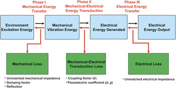
The general principle for conversion of low frequency mechanical stress into electrical energy using a piezoelectric transducer is shown schematically in Figure 2.Reference Kim, Priya, Stephanou and Uchino14 This transformation from mechanical to electrical energy is obtained through the direct piezoelectric effect. The resulting energy can be stored after using a rectifier and dc-dc converter circuit. There are three primary steps in power generation as outlined in this schematic: (1) trapping the mechanical ac stress from the available source, (2) converting the mechanical energy into electrical energy with the piezoelectric transducer, and (3) processing and storing the generated electrical energy. Depending on the frequency and amplitude of the mechanical stress, one can design the required transducer, its dimensions, vibration mode, and the desired piezoelectric material. The power density of a harvesting system is dependent upon the strategies that maximize the trapping of energy and that reduce the losses occurring at each step, namely, mechanical loss due to mismatch in mechanical impedance and electromechanical loss depending upon the magnitude of the electromechanical coupling factor of the piezoelectric material.Reference Jiang and Miles15–Reference Uchino18 The electromechanical coupling factor represents the ratio of input mechanical energy to the output electrical energy or vice-versa.
Energy flow of a piezoelectric generator.Reference Kim, Priya, Stephanou and Uchino14 First, the source excitation is converted into cyclic oscillations through mechanical assembly. This step results in a loss of some energy through unmatched mechanical impedance, damping, and backward reflection. In the second phase, the cyclic mechanical oscillations are converted into cyclic electrical energy through the piezoelectric effect. This step results in loss of some energy through electromechanical losses of piezoelectric material. Electromechanical coupling factor (k) represents the efficiency of the mechanical to electrical conversion process. The product of a piezoelectric stress coefficient (d) and a piezoelectric voltage coefficient (g) represents the material figure of merit. In the third phase, the generated electrical energy is conditioned through rectification and dc/dc conversion. This step results in some losses due to power consumption by the circuit.

Most reported piezoelectric harvesters utilize the resonance of a cantilever beam structure, which amplifies the small ambient vibration into an in-plane strain governed by the Euler–Bernoulli beam equation.Reference Priya and Inman1, Reference Beeby, Tudor and White3, Reference Muralt, Polcawich and Trolier-McKinstry8 This standard governing equation of motion can be used to find the relative displacement that is a function of position and time. The natural frequency of transversal vibration of a continuous cantilever beam can be obtained analytically from the decoupled form of the equation. In order to harvest power robustly, the resonance bandwidth of a linear cantilever beam harvester should be wide enough to accommodate the uncertain variance of ambient vibrations.Reference Hajati and Kim9 Therefore, the resonance bandwidth is an important characteristic for trapping a sufficient amount of energy onto the beam and should be accounted for in determining the performance of energy harvesters.
Piezoelectric MEMS technology is a cost-effective energy harvesting technology if it can meet the requirements for power density and bandwidth. Three major attributes to make the piezoelectric MEMS energy harvesting technology deployable for real applications are the cost of the system, the normalized power density, and the operational frequency range (bandwidth and the center frequency). The current state of the art of piezoelectric MEMS technology is reviewed in this article with respect to these attributes. The physics behind piezoelectric-based power sources is reviewed in this article along with approaches to enhance the power density by addressing the performance of piezoelectric materials and nonlinear structural designs.
Review of piezoelectric energy harvesting
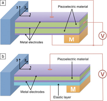
The basic principle of piezoelectric cantilever based energy harvesting can be explained by accounting for the flow of energy between different domains in Phase I and Phase II in Figure 2. Ambient vibrations inject energy into the system through the base excitation at each cycle. This input energy is converted to kinetic energy of the proof mass, M, in Figure 3 and then to potential energy stored as the beam’s mechanical strain.Reference Hajati19 Part of the elastic energy stored in the beam is transformed into electrical energy in the form of induced charge across the piezoelectric layer, which is deposited on the beam. Piezoelectric energy harvesters generally have bimorph or unimorph cantilever beam structuresReference Roundy and Wright11, Reference Renaud, Karakaya, Sterken, Fiorini, Van Hoof and Puers20 (Figure 3). However, at the MEMS scale, bimorph piezoelectric cantilevers are less manufacturable with existing microfabrication processes. For example, lead zirconate titanate (PZT) MEMS devices are mostly spin coated, which makes it very difficult to deposit PZT on the top and bottom of a beam. As a result, MEMS cantilevers mostly have a unimorph configuration. A proof mass is usually attached at the tip of the cantilever to adjust the resonant frequency to the available environmental frequency, normally below 100 Hz.Reference Roundy, Wright and Rabaey21, Reference Reilly, Miller, Fain and Wright22
Basic structures of piezoelectric energy harvesters: (a) bimorph structure that has two independently polarized piezoelectric layers, and (b) unimorph structure that has one piezoelectric layer and an elastic substrate layer. Note: M, proof mass.

Recently, MEMS technologies have been applied toward the development of integrated energy harvesters, and many piezoelectric MEMS energy harvesters have been developed.Reference Beeby, Tudor and White3, Reference Hajati and Kim9, Reference Jeon, Sood, Jeong and Kim12, Reference Roundy, Wright and Rabaey21–Reference Aktakka45 Useful metrics in comparing these devices are their active area, active volume, resonant frequency, harvested power, and power densities in volume or area. Devices with relatively higher power densities (in volume or area) or non-PZT materials such as AlN and lead-free potassium sodium niobate (KNN) are selectively shown in Table I. In order to understand the performance attributes defined earlier and to better compare the devices reported, basic models of vibration kinematics and piezoelectrics are summarized.
Comparison of recent small-scale piezoelectric energy harvesters.

Initial data were taken from Park et al.Reference Park, Park and Lee41 and Aktakka.Reference Aktakka45 Devices with typical non-PZT material are selected.
PZT, lead zirconate titanate; KNN, potassium sodium niobate.
Vibration kinematics
Vibration as a common ambient energy source can be found in household appliances (refrigerators, microwave ovens, washing machines), large civil structures (buildings, bridges), industrial plants (refineries), automobiles, and many other common locations. Table II shows some of the common sources of mechanical energy that can be harnessed through piezoelectrics. Table III quantifies the vibration energy available in some of these environments.Reference Priya46, Reference Marin, Priya and Sodano47
Sources of energy available in the surroundings that can be tapped for generating electricity.
The two rows in this table represent the difference in the scale of the mechanical energy.
Peak acceleration and frequency of common structures.Reference Priya46, Reference Marin, Priya and Sodano47
The general model of a vibration energy harvester is a typical mass-spring-damper system. Maximum power is achieved when the excitation frequency ω is equal to the natural frequency ωn of the system. All practical systems dissipate energy when they vibrate. To account for this, we must consider damping. Maximum extractable electrical power in terms of mass, m, mechanical damping ratio ζm, electrical damping ratio ζe, and acceleration A becomes,
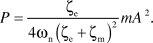 $$P = {{{\rm{\zeta }}_{\rm{e}} } \over {4{\rm{\omega }}_{\rm{n}} \left( {{\rm{\zeta }}_{\rm{e}} + {\rm{\zeta }}_{\rm{m}} } \right)^2 }}mA^2 .$$
Several conclusions can be drawn from Equation 2.Reference Xu48 The extractable power from the beam is inversely proportional to the resonance frequency at a fixed acceleration, A; therefore the energy harvester should be designed for the lowest possible frequency to achieve the highest power. The extractable power is also proportional to the (acceleration),Reference Chandrakasan, Amirtharajah, Goodman and Rabiner2 which limits the energy available for conversion with low acceleration vibrations whatever the specific design is chosen. It can also be seen that power is proportional to the proof mass, so a large proof mass is always desirable for energy harvesting. Finally, the term composed of the mechanical and electrical damping ratio implies that the maximum power is achieved when the electrical damping matches the mechanical damping.Reference Dutoit, Wardle and Kim49 When the electrical damping is equal to mechanical damping (ζe = ζm) , the maximum electrical power that can be generated is given as
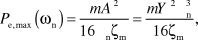 $$P_{{\rm{e}},\max } \left( {{\rm{\omega }}_{\rm{n}} } \right) = {{mA^2 } \over {16{\rm{\omega }}_{\rm{n}} {\rm{\zeta }}_{\rm{m}} }} = {{mY^2 {\rm{\omega }}_{\rm{n}}^{\rm{3}} } \over {16{\rm{\zeta }}_{\rm{m}} }},$$
where the acceleration amplitude A and proof mass deflection Y are related by the relationship
 $$A = {\rm{\omega }}_{\rm{n}}^{\rm{2}} Y.$$
Equation 3 represents the theoretical maximum of extractable power, which can be dissipated in the electrical load. This is actually a limiting factor for all linear resonator based energy harvesters if the transformation capacity of the piezoelectric layer is not a limiting factor. It has been reported that a nonlinear resonator based energy harvester can circumvent this limit and is able to generate much higher power than the mechanical damping, which will be discussed in the next section. Another parameter of interest in the design of thin-film harvesters is the generalized electromechanical coupling (GEMC) factor, K.Reference Renaud, Karakaya, Sterken, Fiorini, Van Hoof and Puers20 The GEMC factor is obtained from the equation:
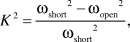 $$K^2 = {{{\rm{\omega }}_{{\rm{short}}} ^2 - {\rm{\omega }}_{{\rm{open}}} ^2 } \over {{\rm{\omega }}_{{\rm{short}}} ^2 }},$$
where ωshort and ωopenare the angular resonance frequencies of the associated short and open circuits, respectively. The GEMC represents the power generation performance of the vibration harvesters, and this value can be theoretically derived from the mechanical properties, thickness ratio, and electromechanical coupling factors of piezoelectric thin films.Reference Wang, Du, Xu and Cross50
Piezoelectrics, energy conversion, and figures of merit
Piezoelectricity is one common outcome of the lack of center of inversion symmetry in the crystal lattice. Piezoelectric generators produce high voltages and low currents and require no voltage source to operate. Some believe they are more difficult to integrate into microsystems due to the high temperature required for crystallization,Reference Roundy, Wright and Rabaey21 but there have been several successful implementations of MEMS scale piezoelectric energy harvesters (see Table I). Piezoelectric energy harvesters can be categorized by their power sources, such as ambient vibrations, impacts, fluid, and human power. Regardless of the vibration energy sources, the basic working principle is the same—the environment applies a stress on the piezoelectric material, and by the direct piezoelectric effect, the input mechanical energy is converted to electrical energy.
Two piezoelectric modes, d 31 or d 33, are commonly used in piezoelectric microdevices (Figure 4). The relative directions of the electric field and the strain distinguish them: d 31 when the electric field is perpendicular to the input strain, and d 33 when they are parallel.Reference Bernstein, Bottari, Houston, Kirkos, Miller, Xu, Ye and Cross51 Conventional MEMS piezoelectric devices/actuators have a d 31 configuration in which a piezoelectric layer is sandwiched between top and bottom electrodes. For a d 31 mode energy harvester, the generated voltage is proportional to the thickness of the piezoelectric layer (txx), the effective piezoelectric constant, g 31,f (Vm/N), and the applied stress, σxx.
 $$V_{31} = \sigma _{xx} g_{31,{\mathop{\rm f}\nolimits} } t_{xx} .$$
Two modes of piezoelectric conversion of input mechanical energy depending on the relative direction of the stress, σ (or strain, ε) and the electric field,  $\overrightarrow {\rm{E}} $.Reference Jeon, Sood, Jeong and Kim12 The bottom drawings show the cross-section of the cantilevers shown above. They are distinguished by whether the electric field is perpendicular to the input stress (or strain) direction (d 31 mode) or parallel to it (d 33mode).

For typical values of g 31,f and acceleration, the generated voltage becomes too small for the rectifying circuits, as the thickness of the piezoelectric layer drops below 1 μm (mostly less than 0.5 μm) in MEMS-scale harvesters. Therefore, the d 31 mode of the piezoelectric device is often not favorable for energy harvesting applications even though the generated power could be higher. For high permittivity ferroelectric piezoelectrics, the d 33 mode can generate higher open-circuit voltages by increasing the spacing between the interdigitated electrodes where polarization wraps from one electrode to the next in alternating directions, as shown in Figure 4. Jeon et al. showed that operating piezoelectric elements in the d 33 mode is more advantageous than in the d 31 mode for MEMS-scale PZT harvesters.Reference Jeon, Sood, Jeong and Kim12 But, recently developed high e 31,f coefficient piezoelectric materials such as epitaxial PZT, Pb[Mg1/3Nb2/3]O3–PbTiO3 (PMN-PT) or AlN can circumvent this problem, enabling d 31mode harvesters.
The power trapped in each cycle from Equation 2 is dissipated to structural and aerodynamic damping as well as to electrical energy via the piezoelectric effect. To maximize the harvested power, the electrical damping needs to be increased, while the structural and aerodynamic damping need to be minimized. With the strain and electromechanical coupling, the electrical power generated via the d 33mode piezoelectric effect of a unimorph cantilever can be expressed as
 $$P_{{\rm{piezo}}} = v_{{\rm{piezo}}} E_{{\rm{piezo}}} S^2 f_{{\rm{exc}}} k_{33}^2 $$
and
 $$k_{33}^2 = {{{\rm{stored}}\_{\rm{energy}}} \over {{\rm{input}}\_{\rm{mechanical}}\_{\rm{energy}}}} = {{d_{33}^2 E_{{\rm{piezo}}} } \over {{\rm{\varepsilon }}_{{\rm{piezo}}} }} = {{e_{33}^2 } \over {{\rm{\varepsilon }}_{{\rm{piezo}}} E_{{\rm{piezo}}} }},$$
where v piezo, E piezo, S, f exc, k 33, and εpiezo are the volume of the piezo material, Young’s modulus, strain, excitation frequency (Hz), electromechanical coupling coefficient, and dielectric permittivity, respectively. As long as the beam’s stored energy minus the mechanical loss (dissipated via structural and aerodynamic damping), which can be defined as “extractable energy,” is bigger than the “conversion energy” from Equation 7, the maximum harvested energy is determined by the piezoelectric layer volume and coupling coefficient. A similar statement can be made for the d 31mode piezoelectric harvesters.
The coupling coefficient described in Equation 7 may only be applied to conditions where the passive elastic layer stiffness can be neglected. For most MEMS energy harvesters where the piezoelectric layer is much thinner compared to the passive elastic layer, Equation 8 may not be accurate. For an energy harvester, which consists of a thin layer of piezoelectric material and a much thicker passive elastic layer, the coupling factor can be written as:Reference Xu and Kim52
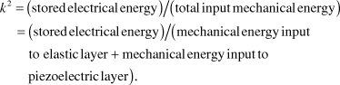 $$\eqalign{ & k^2 = {\rm{stored}}\,{\rm{electrical}}\,{\rm{energy}}/{\rm{total}}\,{\rm{input}}\,{\rm{mechanical}}\,{\rm{energy}} \cr & = {\rm{stored}}\,{\rm{electrical}}\,{\rm{energy}}/\left( {{\rm{mechanical}}\,{\rm{energy}}\,{\rm{input}}\,{\rm{to}}\,{\rm{elastic}}\,{\rm{layer}} + {\rm{mechanical}}\,{\rm{energy}}\,{\rm{input}}\,{\rm{to}}\,{\rm{piezoelectric}}\,{\rm{layer}}} \right). \cr} $$
It can be readily seen that only a portion of the input mechanical energy is injected into the piezoelectric layer to be converted into electrical energy, while much of the energy stays in the elastic layer as strain energy and will not be converted. Therefore, the coupling coefficient will be lower than the real conversion rate of the piezoelectric material.
A more precise figure of merit (FOM) for the piezoelectric energy harvesters can be derived by considering the power response of the piezoelectric transducer. Recently, Oliver and Priya conducted detailed modeling of the piezoelectric cantileverReference Bedekar, Oliver and Priya53 and proposed a dimensionless figure of merit (DFOM) for the piezoelectric transducer material in an energy harvesting application as54
 $${\rm{DFOM}} = \left( {{{k_{31}^2 \cdot Q_{\rm{m}} } \over {s_{11}^{\rm{E}} }}} \right)_{{\rm{on - resonance}}} \left( {{{d_{31} \cdot g_{31} } \over {\tan {\rm{\delta }}}}} \right)_{{\rm{off - resonance}}} ,$$
where k 31 is the transversal electromechanical coupling factor, Q m is the mechanical quality factor (inverse of the Q m represents the mechanical loss), $\overrightarrow {\rm{E}} $ is the elastic compliance at the constant field condition, d 31 is the transversal piezoelectric strain constant, g 31 is the transversal piezoelectric voltage constant, tanδ is the loss factor, and δ is the phase lag between the real and imaginary components of the dielectric constant. Please note the reduced tensor notation here. For example, elastic compliance is a fourth-order tensor but has been written in the reduced form as s 11. The variable 11 indicates that the stress and strain are occurring along the 1-axis of the chosen coordinate system. The DFOM is a product of two FOMs representing off-resonance and on-resonance conditions.
By comparing DFOMs for commercial piezoelectric compositions, the better piezoelectric composition could be identified for energy harvesting applications. Defosseux et al. compared the off-resonance FOM for PZT and AlN and noticed a higher magnitude for AlN (7.8 × 10⁻¹¹ m2/C as compared to 4 × 10⁻¹¹ m2/C for PZT).Reference Defosseux, Allain, Ivaldi, Defay and Basrour55 For PZT, the values were taken to be ε33/εo = 935, d 31 = –110 × 10−12 m/V, and tanδ = 3.6% (measured on PZT 53/47 {100}-textured 2 μm thin filmReference Ledermann, Muralt, Baborowski, Gentil, Mukati, Cantoni, Seifert and Setter56). For AlN, the values were taken to be ε33/εo = 10, d 31 = –2.6 × 10⁻¹² m/V, and tanδ = 0.1% (dielectric properties measured at 10 kHz for a film with a thickness of 2 μm by Martin et al.,Reference Martin, Muralt, Dubois and Pezous57 and piezoelectric properties were reported by Tsubouchi and Mikoshiba for a 1-μm-thick filmReference Tsubouchi and Mikoshiba58). Considering that AlN processing can be made compatible with CMOS, these results indicate the promise of AlN films for developing MEMS energy harvesters.
Challenges of piezoelectric MEMS energy harvesters
Many piezoelectric MEMS energy harvesters have been developed, as listed in Table I. Their form factors are all different and can only be compared with the power density that can be defined as the ratio of generated power over the active material volume (volume power density, μW/mm3) or over the active material area (area power density, μW/mm2). But harvesters with high resonant frequency or those that require high acceleration ambient vibration are less favorable considering the low frequency, low g characteristics of most ambient vibrations. In order to generate a comparative figure, normalization was done with respect to both area and volume of harvesters, natural frequency, and input acceleration.
Based upon Equation 3, the maximum extractable output power is proportional to (1/frequency) and (acceleration)2. From Equation 7, the converted electrical power is proportional to the excitation frequency. Thus, some researchers have taken into account both frequency and acceleration variations by normalizing the power with frequency or (acceleration)2. Most reported devices show orders of magnitude smaller normalized power density than required (see Table I). One of the direct solutions to address this challenge is to improve the electromechanical coupling coefficient of the piezoelectric thin films. Another approach is to seek new resonating beam structure designs from which more energy can be extracted at lower frequency and acceleration.Reference Hajati and Kim9
Another metric commonly used in literature is the normalized FOM, which takes into account bandwidth.Reference Najafi, Galchev, Aktakka, Peterson and McCullagh59 Bandwidth is also an important characteristic and should be accounted for in order to determine the performance of piezoelectric harvesters under unpredictable or uncontrollable spectra of ambient vibrations. Most piezoelectric energy harvesters have been designed based on a linear resonator (e.g., a cantilever with a proof mass). The extractable power of an energy harvester based on a linear resonator is proportional to the gain (quality factor) of the resonator, which is inversely proportional to the bandwidth. If the center frequency of a beam is off by about 2% from the input frequency, the amplitude of the beam bending drops to about 50% of the resonance peak. If it is off by 5%, then there is no resonance to amplify the strain on the piezoelectric material. Accordingly, there is a trade-off between the output power and the bandwidth. Since we cannot control the frequency of ambient vibrations, an energy harvester with a narrow bandwidth (most linear resonators) is impractical in most real applications. Several approaches have been adopted to circumvent this gain-bandwidth dilemma. For example, the natural frequency of resonating beams can be tuned by changing the axial tension of a beam through non-contact mechanisms, such as magnetic attractive and repulsive forces. Beam dimensions and proof mass have also been tuned mechanically to widen the bandwidth.Reference Al-ashtari, Hunstig, Hemsel and Sextro60, Reference Mansour, Arafa and Megahed61 However, frequency tuning inevitably consumes power, the tuning efficiency is low, and the tuning range is limited. Multiple beams of different lengths have also been utilized to address this challenge, which may not be practical in terms of size and cost. Simpler and less costly methods have been sought that can provide both the wide bandwidth and high power density required for practical MEMS-scale devices are described later.
Recent advances in piezoelectric MEMS energy harvesting
In order to address the challenges described previously, advances have been achieved recently in piezoelectric materials and resonating beam structures to achieve higher power densities and wider bandwidth.
Grain textured and epitaxial piezoelectric films
The most simple and direct solution to enhance the output power at the fixed size of a device is to increase the piezoelectric coefficient value. Grain texturing has been shown to be an effective method for improving the magnitude of physical constants in piezoelectrics by achieving a domain-engineered state. In the vicinity of the morphotropic phase boundary (MPB), a rhombohedral composition oriented along the <100> direction is known to exhibit optimum magnitudes of electromechanical coefficients.Reference Uchino62 Several studies have been conducted on tuning the piezoelectric properties through interfacial stress. Recent results by Han et al. have shown ∼90% enhancement of ferroelectric and piezoelectric properties in MPB composition PZT thick films by tailoring the magnitude of residual stress by choosing substrates with different coefficients of thermal expansion.Reference Han, Ryu, Yoon, Choi, Hahn, Kim, Park, Ahn, Priya and Jeong63–Reference Yokoyama, Ozeki, Oikawa and Funakubo66 The results of this study are summarized in Table IV. The electrical properties showed that the films on yttria-stabilized zirconia (YSZ) substrates with highest in-plane compressive stress had the best piezoelectric properties, while that on a Si wafer with tensile in-plane compressive stress showed lower properties. The enhanced piezoelectric properties were attributed to the fact that the c-domains parallel to the thickness direction were easy to form under in-plane compressive stress. This technique of inducing a compressive stress in the films is quite appealing, as it can be easily implemented in the fabrication of MEMS components.
Relationship between in-plane stress and electric/piezoelectric properties in PZT thick films deposited on various substrates.
The effective piezoelectric constants (d 33eff) were measured by the laser beam interferometry method.Reference Han, Ryu, Yoon, Choi, Hahn, Kim, Park, Ahn, Priya and Jeong63
ε, dielectric constant; tanδ, dielectric loss factor; P r, remanent polarization; E c, coercive field; YSZ, yttria-stabilized zirconia.
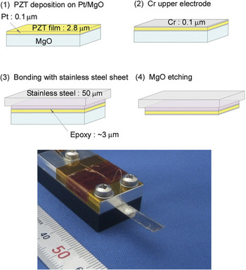
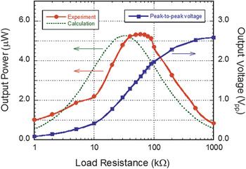
Epitaxial PZT thin films with c-axis orientation are also ideal materials for MEMS energy harvesters because the c-axis orientation of the tetragonal PZT results in large piezoelectric properties and a low dielectric constant.Reference Isarakorn, Briand, Janphuang, Sambri, Gariglio, Triscone, Guy, Reiner, Ahn and de Rooij29, Reference Kanno, Fujii, Kamada and Takayama67 However, epitaxial substrates, such as MgO and SrTiO3, are usually not suitable for unimorph cantilevers because of their brittleness and difficulty of microfabrication. One solution is to transfer the epitaxial PZT films onto flexible cantilevers. Qi et al. transferred epitaxial PZT thin films deposited on MgO substrates to flexible polydimethylsiloxane substrates and evaluated fundamental piezoelectric characteristics.Reference Qi, Kim, Nguyen, Lisko, Purohit and McAlpine68 Morimoto et al. developed high efficiency piezoelectric energy harvesters using c-axis oriented PZT thin films, which were transferred onto stainless steel.Reference Morimoto, Kanno, Wasa and Kotera13 The fabrication process from this study is shown in Figure 5. The c-axis oriented PZT thin films were grown on (100) MgO single crystals with epitaxial (001) Pt bottom electrodes. Reciprocal lattice space maps of the (204) PZT before and after the transfer process clearly show spotty diffractions of the (204) PZT, indicating that the transfer process did not degrade the crystal structure of the epitaxial PZT film. After the PZT film was bonded to 50-μm-thick stainless steel sheets with epoxy resin, the MgO substrate was etched out using phosphoric acid. A photograph of a stainless steel cantilever beam covered with the epitaxial PZT is shown in Figure 5. The relative dielectric constant εr of the transferred films on stainless steel was as low as 166, while the piezoelectric coefficient e 31,f of the transferred PZT films was around −6 C/m2. The thickness and length of the stainless steel cantilever were 50 μm and 18.5 mm, respectively. Because of the thin dimensions of the metal cantilever, the first resonance was found to occur at 126 Hz.Reference Morimoto, Kanno, Wasa and Kotera13 Experimental peak-to-peak voltage, and experimental and calculated averaged output power are plotted in Figure 6 (acceleration: 5 m/s2). A maximum output electric power of 5.3 μW across a load resistance of 50 kΩ was measured. In this measurement, the GEMC, K 2, was calculated to be 1.3 × 10⁻², which is much larger than the value for polycrystalline PZT thin films on Si substrates.Reference Renaud, Karakaya, Sterken, Fiorini, Van Hoof and Puers20 This result was attributed to the large electromechanical coupling coefficient k 31 of c-axis oriented epitaxial PZT thin films. The output power increased monotonically with acceleration, reaching 244 μW at 50 m/s2. The flexible metal cantilever enables considerable reduction of the resonant frequency and offers enhanced toughness compared with brittle Si-based cantilevers.
Fabrication flow and photograph of transferring epitaxial lead zirconate titanate (PZT) thin films to a stainless steel cantilever:Reference Morimoto, Kanno, Wasa and Kotera13 (step 1) deposition of c-axis oriented PZT thin films on Pt/MgO; (step 2) deposition of Cr top electrode; (step 3) bonding the PZT thin films to a stainless steel cantilever; and (step 4) etching out the MgO substrate.

Output voltage and generated power of transferred epitaxial lead zirconate titanate (PZT) thin films on a stainless steel cantilever as a function of load resistance.Reference Morimoto, Kanno, Wasa and Kotera13 The maximum output power reached 5.3 μW at the low acceleration of 5 m/sReference Chandrakasan, Amirtharajah, Goodman and Rabiner2 due to the large electromechanical coupling factor k 31 of c-axis oriented PZT thin films.

It is well-known that oriented relaxor ferroelectric single crystals, such as Pb(Mg1/3Nb2/3)O3-PbTiO3 (PMN-PT) and Pb(Zn1/3Nb2/3)O3-PbTiO3 (PZN-PT), show about a 10 times larger piezoelectric coefficient than conventional PZT ceramics due to the domain engineered state.Reference Park and Shrout69, Reference Kuwata, Uchino and Nomura70 Recently, Baek et al. successfully grew epitaxial PMN-PT thin films on SrTiO3–buffered miscut Si substrate by off-axis sputtering (see the Baek et al. article in this issue). The piezoelectric coefficient e 31,f in their work was reported to be −27 C/m2, which is the highest value ever reported.Reference Baek, Park, Kim, Aksyuk, Das, Bu, Felker, Lettieri, Vaithyanathan, Bharadwaja, Bassiri-Gharb, Chen, Sun, Folkman, Jang, Kreft, Streiffer, Ramesh, Pan, Trolier-McKinstry, Schlom, Rzchowski, Blick and Eom71 Using these films, they fabricated a unimorph micro-cantilever and confirmed the excellent inverse piezoelectric performance. Because of the large electromechanical coupling coefficient k 31 (or figure of merit: e Reference Chandrakasan, Amirtharajah, Goodman and Rabiner231,f/εr) of PMN-PT epitaxial thin films, this system is quite promising for improving the performance of current MEMS energy harvesters.
Lead-free piezoelectric films
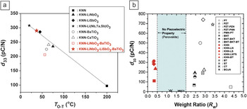
For powering medical implants and human use of energy harvesters, a lead-free piezoelectric material is desirable due to the toxicity of Pb. Potassium sodium niobate (KxNa1−xNbO3), or KNN, is considered to be a very promising lead-free piezoelectric material owing to its high Curie temperature and high ferroelectric orthorhombic—ferroelectric tetragonal transition temperature.Reference Ahn, Choi, Park, Nahm and Priya72 The piezoelectric properties of KNN-based compositions are directly correlated to the fraction of orthorhombic (O) and tetragonal (T) phases, as shown in Figure 7a. One of the strategies for achieving a higher piezoelectric response has been to modulate the composition such that the O/T transition lies close to room temperature.Reference Ahn, Park, Viehland, Nahm, Kang, Bae and Priya73 Another strategy adopted for designing lead-free compositions is based upon the trend between the atomic weight ratio of A to B sites (R w = W a/W b) and the longitudinal piezoelectric constant d 33, as shown in Figure 7b.Reference Ahn, Maurya, Park, Nahm and Priya74 It can be observed that 1/R w for KNN ceramics (for Na/K ratio of 0.5) is similar to R w for PZT ceramics at the MPB composition, and both of these materials exhibit high piezoelectric response. Piezoelectric compositions show a large response when R w for A-site heavy perovskites and 1/R wfor B-site heavy perovskites are higher than 2.0.
A piezoelectric coefficient can be tuned by adjusting the intermediate phase transition temperature in a polymorphic phase boundary system and A-site to B-site weight ratio in perovskites. (a) Variation of longitudinal piezoelectric coefficient (d 33) with orthogonal phase (O)−tetragonal phase (T) transition temperature (T O-T) in the potassium sodium niobate (KNN) system;Reference Ahn, Park, Viehland, Nahm, Kang, Bae and Priya73 (b) variation of longitudinal piezoelectric coefficients as a function of weight ratio in bulk perovskites.Reference Ahn, Maurya, Park, Nahm and Priya74 PT, PbTiO3; PZT, Pb(Zr,Ti)O3; PZN, Pb(Zn1/3Nb2/3)O3; PNN, Pb(Ni1/3Nb2/3)O3; PMN, Pb(Mg1/3Nb2/3)O3; BNT, (Na1/2Bi1/2)TiO3; BKT, (K1/2Bi1/2)TiO3; BT, BaTiO3; LN, LiNbO3; LS, LiSbO3; LNTS, (Li,Na)(Ta,Sb)O3; ST, SrTiO3; CT, CaTiO3; BCuN, Ba(Cu1/3Nb2/3)O3. Clearly, a large piezoelectric coefficient is obtained by shifting T O-Ttoward room temperature and by keeping the weight ratio within a narrow range.

The fabrication process of these lead-free piezoelectric materials in thin-film form is still under development, and it is expected that these materials will be utilized in the design of MEMS energy harvesters in the near future. Recently, Shibata et al. reported that KNN thin films deposited by radio frequency (RF) magnetron sputtering showed large transverse piezoelectric properties comparable to those of PZT thin films.Reference Shibata, Suenaga, Watanabe, Horikiri, Nomoto and Mishima75 Kanno et al. have compared the energy harvesting performance of KNN thin films with PZT thin films by using simple unimorph Si-cantilevers.Reference Kanno, Ichida, Adachi, Kotera, Shibata and Mishima76 The piezoelectric coefficient of both KNN and PZT films showed almost the same value of e 31,f = −10 C/m2.Reference Muralt77 The relative dielectric constants of the KNN and PZT films were 744 and 872, respectively. Measurements were performed at the resonance frequency of each cantilever (KNN: 1.0 kHz, PZT: 0.89 kHz; acceleration 10 m/sReference Chandrakasan, Amirtharajah, Goodman and Rabiner2). Peak output power for the KNN and PZT films was 1.1 μW at 1.7 kΩ and 1.0 μW at 1.2 kΩ, respectively. Because KNN and PZT thin films have almost the same dielectric and piezoelectric properties, the KNN film performs comparably to the PZT film with respect to power generation. GEMC K Reference Chandrakasan, Amirtharajah, Goodman and Rabiner2 of KNN and PZT energy harvesters was around 0.6∼1.7 × 10⁻³, as determined by fitting the calculated value of Equation 5 to experimental results.Reference Kanno, Ichida, Adachi, Kotera, Shibata and Mishima76
Aluminum nitride─A MEMS compatible piezoelectric film
Recently, significant progress has been made toward incorporating AlN films in energy harvesting applications. van Schaijk et al. have demonstrated the performance of micomachined AlN cantilevers and have shown that a device with dimensions of 3 × 1.3 mm2 was able to provide 10 μW at the resonance frequency of 1155 Hz under 8g acceleration.Reference van Schaijk, Elfrink, Kamel and Goedbloed78 Under practical acceleration values of 1g or lower, the power generated was smaller than 1 μW. Heidrich et al. have investigated the energy generation from [001] textured AlN cantilevers and corrugated membranes for bio-implants.Reference Heidrich, Knoebber, Sah, Pletschen, Hampl, Cimalla and Lebedev79 The growth was conducted on Si(001) substrates, which resulted in tensile (< +300 MPa) and compressive strains (> −100 MPa), depending upon the deposition parameters. In the non-resonant condition of 70 Hz, for a 3 × 4 corrugated membrane array (radius of individual membrane = 400 μm), a peak power of 10 μW was measured across 10 kΩ with a bias of 1 V and an acceleration of 0.01g.Reference Heidrich, Knoebber, Sah, Pletschen, Hampl, Cimalla and Lebedev79 Yen et al. conducted detailed experimentation and modeling of the corrugated AlN cantilever structures. At a resonance frequency of 853 Hz, a cantilever with a width of 2400 μm, a length of 500 μm, and a 2-μm-thick piezoelectric layer was able to provide 0.17 μW under an acceleration of 1g using a tip mass of dimensions 2400 × 500 × 680 μm3.Reference Yen, Hirasawa, Wright, Pisano and Lin80
Stoppel et al. conducted a simulation study in this area that computed the effect of thickness on power generation.Reference Stoppel, Schroeder, Senger, Wagner and Benecke81 It was pointed out that since the Young’s modulus of AlN (345 GPa) is about 4x that of PZT, the thickness of AlN for maximum power output is about 3x smaller than that of PZT. For a cantilever with 2-μm-thick AlN operating at a resonance frequency of 105.6 Hz under an acceleration of 1 m/s2, an output power of 0.8 μW was measured across a 21 MΩ load. Based upon the experimental data available in the literature, the normalized output power (power/frequency × acceleration) for AlN microdevices ranges between 2.034 × 10⁻⁵ and 757 × 10−5 μW/(Hz × m/s2). Ignoring the data from Stoppel et al., the spread is more reasonable from 2.034 × 10⁻⁵ to 11 × 10−5 μW/(Hz × m/s2). These values are quite good, and considering the compatibility of AlN with CMOS processing and the long history in optimizing the deposition process, we expect that this area will continue to grow.
Nonlinear resonance-based energy harvesting structures
Most of the reported vibration energy harvesters use a linear cantilever resonator structure to amplify small ambient vibrations. While such structures are easy to model, design, and build, they typically have a narrow bandwidth. In contrast, nonlinear resonators have a different dynamic response and greatly increase the bandwidth by hardening or softening the resonance characteristics of the beam structure. In addition, it has been found that nonlinear resonating beams can extract more electrical energy than linear resonating beams.Reference Hajati and Kim9, Reference Marinkovich and Koser82
Nonlinearity may come from a magnetic force or constrained mechanical structures. The magnetic force between the iron mass at the tip of a cantilever and an external magnet (or vice versa) creates a nonlinear spring, whose nonlinearity is determined by the strength of the magnets and the size of the air gap between the magnets and the iron stator. Due to the mutual attraction, the ferromagnetic beam has three equilibrium positions (statically bi-stable configuration), and the vibration mode has the form of the bi-stable Duffing resonance. Electromagnetic energy harvesters have been reported showing hardening or softening resonance characteristics.Reference Mann and Sims83–Reference Andò, Baglio, Trigona, Dumas, Latorre and Nouet86 However, magnet-based beams require assembly of hard magnets, which is expected to be costly as the size of the device shrinks.
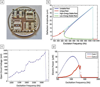
Nonlinear resonance could be better achieved by monolithically fabricated MEMS structures. Efforts have been made to achieve wide bandwidth piezoelectric energy harvesters by exerting axial compression and forming a buckled configuration to make a bi-stable oscillator.Reference Cottone, Gammaitoni, Vocca, Ferrari and Ferrari87 Recently, Hajati et al. demonstrated a monolithic MEMS-based nonlinear resonant piezoelectric micro energy harvester, which achieved an ultra-wide bandwidth of >20% of the center frequency and generated power more than 22 μW (see Figure 8).Reference Hajati and Kim9 More than one order of magnitude improvements were demonstrated compared to devices previously reported for the power bandwidth (see Table I). The basic design is based on a doubly clamped beam resonator with dimensions of 6 mm × 6 mm × 5.5 μm (length × width × height) and a PZT thickness of 0.25 μm. Four of these resonators are arranged perpendicular to each other and form one energy harvester, which is about the size of a US quarter coin (Figure 8a). At large deflection (exceeding 2–3 times the thickness of the beam), a net stretching in addition to bending results, changing the dynamic response to a nonlinear one (Figure 8b). Based on the measured open-circuit voltage in Figure 8c, the internal capacitance (8.5 nF), and resistance (3.5 MΩ) of the measurement circuit, the generated power is estimated as shown in Figure 8d. The result shows orders of magnitude improvement in bandwidth, as compared in Table I.
The fabricated nonlinear beam microelectromechanical systems energy harvester shows ultra-wide bandwidth and high power density energy harvesting: (a) fabricated device on a US quarter dollar coin; (b) simulated dynamic response of a nonlinear resonator, which shows a tilted resonance peak; (c) measured open-circuit voltage versus excitation frequency; (d) Curve 1: extractable strain energy stored in the beam, and Curve 2: generated power 45 μW. By increasing the thickness of the piezoelectric layer to 0.75 μm, up to 80 μW can be harvested at the same harvesting condition.Reference Hajati and Kim9

Unlike a linear resonance system, where the electrical damping cannot exceed the mechanical damping,Reference Dutoit, Wardle and Kim49 Hajati et al. showed that electrical damping in a nonlinear resonance system could surpass the mechanical damping, extracting a much higher output power than that of the linear systems. The nonlinear impedance serves as a negative feedback and stabilizes the deflection when the electrical damping changes.Reference Xu, Hajati and Kim88 This is why the power bandwidth of nonlinear systems can be much wider than that of linear systems at equivalent beam dimensions. A smart electronic interface such as adaptive synchronized switch harvesting on an inductor will be ideal to extract high power from nonlinear beam harvesters.Reference Badel, Guyomar, Lefeuvre and Richard89
Summary
Microelectromechanical system (MEMS) piezoelectric energy harvesters with ∼mm3dimensions will lead to battery-less autonomous sensor systems and networks with 10s to 100s of μW of power that can be extracted from the ambient vibration continuously, robustly, and at low cost. The key attributes to make a good piezoelectric MEMS energy harvester include its compactness, output voltage, bandwidth, operating frequency, input vibration amplitude, lifetime, and cost. Among them, higher power density and wider bandwidth of resonance are the two biggest challenges currently facing the technology. But the state of the art is still about one order smaller than what is needed for practical applications. Recent advances in piezoelectric materials and harvester structural design, individually or in combination, are bringing us closer to battery-less autonomous sensor systems and networks. Giant piezoelectric coefficient materials, epitaxially grown films, grain textured piezoelectric materials and thin films, and high performance lead-free piezoelectric materials are recent advancements made toward increasing the electromechanical energy conversion of piezoelectric harvesters. Nonlinear resonators are extremely promising to extract more electrical energy from the beam with much wider bandwidth. We expect that in the near future, a coin-sized harvester will be able to harvest about 100 μW of continuous power below 100 Hz at less than 0.5 g vibration and at reasonable cost.
Acknowledgments
The authors acknowledge the support from the Office of Basic Energy Sciences, Department of Energy (#DE-FG02–07ER46480) and (DE-FG02–09ER46577), AFOSR Young Investigator Program, DARPA Grant (HR0011–06–1-0045), MIT-Iberian Nanotechnology Laboratory Program.