

1 Introduction
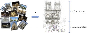
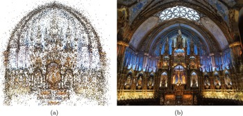
Recovering the three-dimensional structure of a scene from images is a fundamental goal of computer vision. A particularly effective approach to three-dimensional (3D) reconstruction involves the use of many images of a stationary scene. This problem, commonly referred to as multiview structure from motion (multiview SfM) (depicted in Figure 1.1), is the subject of a large body of research in computer vision, starting with the seminal paper of Longuet-Higgins (Reference Longuet-Higgins1981). A comprehensive and in-depth summary of this enormous body of work can be found in Hartley and Zisserman (Reference Hartley and Zisserman2000).
Modern methods usually solve the multiview SfM problem via bundle adjustment techniques, which aim to optimize a cost function known as the total reprojection error; see Section 4 for a more detailed and general discussion of bundle adjustment. With this cost function, given
 $n$
images of a stationary scene, the objective is to simultaneously determine the structure (3D coordinates of scene points) and the calibration parameters of each of the
 $n$
cameras that minimize the discrepancy between image measurements and their predictive model. For instance, in the specific case of pairwise point correspondences between images, we let
 $\{\mathbf{P}_{j}\}_{j=1}^{p}\subseteq \mathbb{R}^{3}$
denote the unknown positions of scene points, and let
 $\{C_{i}\}_{i=1}^{n}$
be the
 $3\times 4$
camera matrices, where the entries of each
 $C_{i}$
encode the location of camera
 $i$
, its orientation and internal calibration parameters. Also, let
 $(x_{ij},y_{ij})\in \mathbb{R}^{2}$
denote the measured projection of point
 $\mathbf{P}_{j}$
onto the image plane of camera
 $C_{i}$
. Then we can define a (relatively simple) bundle adjustment problem based on minimizing the sum of squares cost function
 $$\begin{eqnarray}\underset{\{\mathbf{P}_{j}\},\{C_{i}\}}{\text{minimize}}~~\mathop{\sum }_{i\sim j}\biggl(x_{ij}-\displaystyle \frac{C_{i1}^{T}\mathbf{P}_{j}}{C_{i3}^{T}\mathbf{P}_{j}}\biggr)^{2}+\biggl(y_{ij}-\displaystyle \frac{C_{i2}^{T}\mathbf{P}_{j}}{C_{i3}^{T}\mathbf{P}_{j}}\biggr)^{2},\end{eqnarray}$$
where
 $C_{ik}\in \mathbb{R}^{4}$
denotes the
 $k$
th row of
 $C_{i}$
(
 $1\leq k\leq 3$
),
 $i\sim j$
means that the
 $j$
th scene point is visible by the
 $i$
th camera, and we abuse notation and identify the representation
 $[\mathbf{P}_{j},1]\in \mathbb{R}^{4}$
of
 $\mathbf{P}_{j}$
in homogeneous coordinates by
 $\mathbf{P}_{j}$
. Unfortunately, as a result of the special structure of the camera matrices and the cost function in (1.1), the bundle adjustment problem (1.1) is not convex, and its (naïve) optimization in realistic settings typically converges to an often undesired local minimum. It is therefore critical to develop methods that can initialize bundle adjustment, that is, provide initial camera motion (and intrinsic calibration) and 3D structure estimates, as closely as possible to the true solution.
The structure from motion (SfM) problem.

Snavely, Seitz and Szeliski (Reference Snavely, Seitz and Szeliski2006) presented a sequential pipeline for SfM, demonstrating that it can produce accurate reconstructions in practical scenarios where hundreds or even thousands of independently captured photographs are provided, and sparked huge interest in the development of efficient SfM techniques for large unordered image sets (see Section 4). The suggested pipeline begins by detecting keypoints in each image. It then uses the SIFT descriptor (Lowe Reference Lowe2004) to compare those keypoints across images and to produce a set of potential matches. Random sampling and consensus (RANSAC: Bolles and Fischler Reference Bolles and Fischler1981) is then used to robustly estimate essential matrices between pairs of images (for computation of relative motion of camera pairs) and to discard outlier matches. Then, starting with a pair of images for which the largest number of inlier matches were found and then greedily adding one image at a time, bundle adjustment is solved repeatedly. Although this sequential pipeline is computationally challenging, it successfully deals with large collections of images, in many cases producing highly accurate reconstructions. However, it is based on greedy steps that may not result in an optimal solution. Clearly, global approaches, which consider all images simultaneously (at least for initial camera motion estimation), may potentially yield improved solutions. Indeed, a number of recent methods attempt to estimate camera locations and orientations globally. In this survey, for the initial camera motion estimation part of SfM, we focus on methods for camera location estimation in Section 3, and refer the reader to other surveys that review the problems of camera orientation and calibration recovery (Tron, Zhou and Daniilidis Reference Tron, Zhou and Daniilidis2016).
The outline of this survey is as follows. In Section 2 we briefly discuss some of the early works in the literature that introduced the basic SfM framework and the relatively simple factorization methods. Section 3 covers some of the recent work on camera location estimation from pairwise keypoint matches, such as the simpler least-squares methods based on the (homogeneous) epipolar constraints, relatively stable convex methods based on a linearized representation (see (3.8)) of pairwise direction measurements and heuristic methods for outlier rejection in pairwise directions. In Section 4 we provide some of the key ideas and methods in the literature for 3D structure estimation, with an emphasis on contemporary methods aimed at processing large unordered sets of images. In Section 5 we discuss details of influential works on the simultaneous localization and mapping (SLAM) problem, which has recently experienced a dramatic increase in popularity. Section 6 considers some of the remaining crucial topics in the vast SfM literature, including methods for feature point extraction and matching, works on handling instabilities induced by symmetries and ambiguities in the images, methods for relatively uncommon types of cameras (e.g. omnidirectional cameras), techniques using alternative basic measurements (e.g. based on lines instead of feature points), and some of the important software packages and popular datasets. We conclude in Section 7 with a discussion of the current state of the art and possible future directions for the SfM problem.
Rather unfortunately, as is the case for any survey of a topic for which there is an extensive body of literature, we are unable to cover every important work in the field. In essence, we try to focus on relatively recent SfM techniques. For earlier works in the literature, we refer the reader to other sources, for example Triggs, McLauchlan, Hartley and Fitzgibbon (Reference Triggs, McLauchlan, Hartley and Fitzgibbon2000), Hartley and Zisserman (Reference Hartley and Zisserman2000) and Oliensis (Reference Oliensis2000).
2 Early works
This section covers some of the relatively early works on SfM, which introduced the basic problem formalism and the factorization-based methods. We first consider the seminal work by Longuet-Higgins (Reference Longuet-Higgins1981), who introduced the first linear method based on point correspondences, later named the eight-point algorithm, to solve the SfM problem for a pair of cameras. Specifically, for a pair of cameras, Longuet-Higgins (Reference Longuet-Higgins1981) aimed to estimate the relative camera motion, that is, relative rotation and translation, and the 3D coordinates of the scene points captured by these cameras. Here we represent the
 $i$
th camera by
 $(R_{i},\mathbf{t}_{i})$
, where
 $R_{i}\in \text{SO}(3)$
is the camera’s orientation matrix and
 $\mathbf{t}_{i}\in \mathbb{R}^{3}$
is its position. Considering that we can always fix the (intrinsic) coordinate system of one of the two cameras to be the global coordinate system (i.e. we can set
 $R_{i}=I$
and
 $\mathbf{t}_{i}=\mathbf{0}$
, since an absolute coordinate system cannot be determined from point correspondences), solving for the relative motion for a camera pair, and for the scene points based on the computed motion, then corresponds to actually solving the SfM problem for the pair. The problem setupFootnote
1
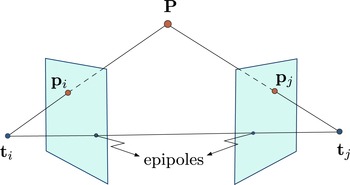
involves a simple pinhole camera model, in which a scene point
 $\mathbf{P}\in \mathbb{R}^{3}$
is represented in the
 $i$
th image plane by
 $\mathbf{p}_{i}\in \mathbb{R}^{3}$
, as shown in Figure 2.1; see also Özyeşil et al. (Reference Özyeşil, Singer and Basri2015, Section 4) and Hartley and Zisserman (Reference Hartley and Zisserman2000), for example. Here, we obtain
 $\mathbf{p}_{i}$
by first representing
 $\mathbf{P}$
, in the
 $i$
th camera’s coordinate system, as
 $\mathbf{P}_{i}=R_{i}^{T}(\mathbf{P}-\mathbf{t}_{i})=(\mathbf{P}_{i}^{x},\mathbf{P}_{i}^{y},\mathbf{P}_{i}^{z})^{T}$
, and then projecting it onto the
 $i$
th image plane via
 $\mathbf{p}_{i}=(f_{i}/P_{i}^{z})\mathbf{P}_{i}$
, where
 $R_{i}\in \text{SO}(3)$
denotes the orientation matrix,
 $\mathbf{t}_{i}\in \mathbb{R}^{3}$
denotes the location of the focal point, and
 $f_{i}\in \mathbb{R}^{+}$
is the focal length of the
 $i$
th camera. For a pair of cameras
 $i$
and
 $j$
as in Figure 2.1, we can restate the coplanarity of the points
 $\mathbf{P},\mathbf{t}_{i}$
and
 $\mathbf{t}_{j}$
, that is,
 $[(\mathbf{P}-\mathbf{t}_{i})\times (\mathbf{P}-\mathbf{t}_{j})]^{T}(\mathbf{t}_{i}-\mathbf{t}_{j})=0$
, in terms of the observable corresponding point measurements
 $\mathbf{p}_{i},\mathbf{p}_{j}$
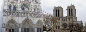
(see Figure 3.1 below for a depiction of a set of corresponding points between a pair of images) and the camera parameters as
 $$\begin{eqnarray}\mathbf{p}_{i}^{T}([R_{i}^{T}(\mathbf{t}_{j}-\mathbf{t}_{i})]_{\times }R_{i}^{T}R_{j})\mathbf{p}_{j}=:\mathbf{p}_{i}^{T}E_{ij}\mathbf{p}_{j}=0,\end{eqnarray}$$
where
 $[\mathbf{t}]_{\times }$
is the skew-symmetric matrix corresponding to the cross-product with
 $\mathbf{t}$
, and
 $E_{ij}=[R_{i}^{T}(\mathbf{t}_{j}-\mathbf{t}_{i})]_{\times }R_{i}^{T}R_{j}$
is the essential matrix for the cameras
 $i$
and
 $j$
. Also, let
 $T_{ij}:=[R_{i}^{T}(\mathbf{t}_{j}-\mathbf{t}_{i})]_{\times }$
and
 $R_{ij}:=R_{i}^{T}R_{j}$
, yielding
 $E_{ij}=T_{ij}R_{ij}$
. Longuet-Higgins (Reference Longuet-Higgins1981) made the crucial observation that, among the various equivalent restatements of the coplanarity of
 $\mathbf{P},\mathbf{t}_{i}$
and
 $\mathbf{t}_{j}$
, the useful property of (2.1), known as the epipolar constraint, is that it provides a basis for the estimation of the structured essential matrices in terms of the observable corresponding points. In other words, by fixing the undetermined scale for the entries of
 $E_{ij}$
(e.g. the Frobenius norm
 $\Vert E_{ij}\Vert _{F}=1$
, or as in Longuet-Higgins (Reference Longuet-Higgins1981)
 $\Vert \mathbf{t}_{j}-\mathbf{t}_{i}\Vert =1$
, which is equivalent to
 $\Vert E_{ij}\Vert _{F}=\sqrt{2}$
), we can solve for
 $E_{ij}\in \mathbb{R}^{3\times 3}$
from eight linearly independent epipolar constraints (2.1) corresponding to eight 3D points.Footnote
2
Longuet-Higgins (Reference Longuet-Higgins1981) did not provide any algorithm for this purpose, nor did he consider the effects of uncertainties (i.e. noise) in the corresponding point measurements; however, the usual approach in the literature is simply to minimize the sum of squared errors in the epipolar constraints subject to the scale constraint, which is equivalent to finding the singular vector corresponding to the smallest singular value of the resulting data matrix. After estimating
 $E_{ij}$
(up to a sign to be determined later), Longuet-Higgins (Reference Longuet-Higgins1981) solved for
 $T_{ij}$
(up to another sign, again to be determined later) by eliminating
 $R_{ij}$
using
 $E_{ij}E_{ij}^{T}=T_{ij}T_{ij}^{T}$
. He then solved for
 $R_{ij}$
, based on its orthogonality, and for the scene points using simple algebraic equations (see Longuet-Higgins Reference Longuet-Higgins1981 for details). Lastly, the undetermined signs of
 $E_{ij}$
and
 $T_{ij}$
are fixed by requiring the scene points to lie in front of both cameras. If the scene points are behind both cameras, the sign of
 $T_{ij}$
is altered, and the relative rotation
 $R_{ij}$
and the scene points are recalculated. If the scene points fall behind one of the two cameras, the sign of
 $E_{ij}$
is altered, and
 $T_{ij},R_{ij}$
and the scene points are recalculated. Further, Longuet-Higgins (Reference Longuet-Higgins1981) briefly discussed some of the degenerate cases of eight 3D points for which the eight-point estimation cannot be used, for example the cases of all points corresponding to the vertices of a cube, at least seven points lying on a plane, six of the eight points corresponding to the vertices of a regular hexagon, or at least four points lying on a line. We note that although Longuet-Higgins (Reference Longuet-Higgins1981) argued for the accuracy of the eight-point algorithm, it was in fact observed to be sensitive to noise, which resulted in the construction of alternative methods, such as a normalized version of the eight-point algorithm (Hartley Reference Hartley1997), for relative pairwise motion estimation. For further reading on alternative methods to obtain epipolar geometries between images, see for example Zhang (Reference Zhang1998) and Hartley and Zisserman (Reference Hartley and Zisserman2000).
The pinhole camera model.

Another early work in the literature is that of Tomasi and Kanade (Reference Tomasi and Kanade1992), who introduced the factorization method for SfM. To model the SfM problem for objects that are relatively distant compared to their sizes, Tomasi and Kanade (Reference Tomasi and Kanade1992) assumed an orthographic camera model, in which the 3D points are measured via parallel projections onto the image plane, consequently ignoring the camera translation along the optical axis. Let the location of the
 $j$
th 3D point on the
 $j$
th camera plane be given by
 $\mathbf{q}_{ij}=(x_{ij},y_{ij})\in \mathbb{R}^{2}$
. In the noiseless case, these orthographic measurements of
 $m$
3D points by
 $n$
cameras are represented in terms of a measurement matrix
 $W\in \mathbb{R}^{2n\times m}$
satisfying
 $$\begin{eqnarray}W=\left[\begin{array}{@{}ccc@{}}x_{11} & \ldots & x_{1m}\\ \vdots & \ddots & \vdots \\ x_{n1} & \ldots & x_{nm}\\ y_{11} & \ldots & y_{1m}\\ \vdots & \ddots & \vdots \\ y_{n1} & \ldots & y_{nm}\end{array}\right]\!.\end{eqnarray}$$
The crucial observation made by Tomasi and Kanade (Reference Tomasi and Kanade1992) is that if the origin of the global reference system is chosen to be at the centre of the 3D structure points (implying that each row of
 $W$
sums to zero), then
 $W$
can be decomposed into
 $$\begin{eqnarray}W=RS,\quad \text{for }R=\left[\begin{array}{@{}c@{}}\mathbf{u}_{1}^{T}\\ \vdots \\ \mathbf{u}_{n}^{T}\\ \boldsymbol{ v}_{1}^{T}\\ \vdots \\ \mathbf{v}_{n}^{T}\end{array}\right]\in \mathbb{R}^{2n\times 3}\quad \text{and}\quad S=[\mathbf{P}_{1}\ldots \mathbf{P}_{m}]\in \mathbb{R}^{3\times m},\end{eqnarray}$$
where
 $\mathbf{u}_{k}$
and
 $\mathbf{v}_{k}$
represent the orientation of the
 $k$
th camera (since, in the orthographic model, the third direction given by
 $\mathbf{u}_{k}\times \mathbf{v}_{k}$
is parallel to the viewing direction of the cameras) and
 $\mathbf{P}_{k}$
is the
 $k$
th 3D point. As a result,
 $W$
has rank
 $3$
. In the noisy case, which may result in a higher rank for
 $W$
, Tomasi and Kanade (Reference Tomasi and Kanade1992) considered a valid measurement matrix to be given by the best rank-
 $3$
approximation to the noisy
 $W$
in the Frobenius norm sense, which is given by the singular value decomposition (SVD). Note that replacing
 $R$
and
 $S$
with
 $RQ$
and
 $Q^{-1}S$
, for an arbitrary invertible matrix
 $Q\in \mathbb{R}^{3\times 3}$
, results in the same measurement matrix
 $W$
. As a result, in order to compute
 $R$
and
 $S$
from
 $W$
, Tomasi and Kanade (Reference Tomasi and Kanade1992) proposed first computing a decomposition of
 $W$
using SVD, and then solving for
 $Q$
using the orthonormality of the
 $n$
pairs
 $(\mathbf{u}_{k},\mathbf{v}_{k})$
. That is, for
 $W=U_{W}\unicode[STIX]{x1D6F4}_{W}V_{W}^{T}$
representing the SVD of
 $W$
, they first let
 $\hat{R}=U_{W}\unicode[STIX]{x1D6F4}^{1/2}$
and
 ${\hat{S}}=\unicode[STIX]{x1D6F4}^{1/2}V_{W}^{T}$
, and then computed the solution
 $R=\hat{R}Q$
and
 $S=Q^{-1}{\hat{S}}$
, where
 $Q$
is given to be a solution to the non-linear system of
 $3n$
equations
 $$\begin{eqnarray}\hat{\mathbf{u}}_{k}^{T}QQ^{T}\hat{\mathbf{u}}_{k}=\hat{\mathbf{v}}_{k}^{T}QQ^{T}\hat{\mathbf{v}}_{k}=1,\quad \hat{\mathbf{u}}_{k}^{T}QQ^{T}\hat{\mathbf{v}}_{k}=0,\quad k=1,\ldots ,n,\end{eqnarray}$$
where
 $\hat{\mathbf{u}}_{k}$
and
 $\hat{\mathbf{v}}_{k}$
represent the
 $k$
th and
 $(k+n)$
th rows of
 $\hat{R}$
(see (2.3)). They also extended the factorization method to the case of occlusions (i.e. to the case when some scene points are not visible by all of the cameras) and provided empirical evidence demonstrating the stability of their factorization approach on various experimental scenarios.
Sturm and Triggs introduced an extension of the factorization methodology for the multiview SfM with perspective cameras. They considered the basic image projection equations
 $$\begin{eqnarray}\unicode[STIX]{x1D706}_{ij}\mathbf{p}_{ij}=C_{i}\mathbf{P}_{j},\quad i=1,\ldots ,n,\quad j=1,\ldots ,m,\end{eqnarray}$$
where, for the
 $j$
th 3D point represented (by abuse of notation) in the homogeneous coordinates by
 $\mathbf{P}_{j}\in \mathbb{R}^{4}$
and
 $C_{i}$
denoting the
 $i$
th camera matrix,
 $\mathbf{p}_{ij}\in \mathbb{R}^{3}$
is the projection of the
 $j$
th point onto the
 $i$
th camera plane (in the homogeneous coordinates) and
 $\unicode[STIX]{x1D706}_{ij}$
are the undetermined scales, called projective depths. Similarly to Tomasi and Kanade (Reference Tomasi and Kanade1992), Sturm and Triggs (Reference Sturm and Triggs1996) collected these projective measurements into a rank-
 $4$
measurement matrix
 $Y\in \mathbb{R}^{3n\times m}$
given by
 $$\begin{eqnarray}Y=\left[\begin{array}{@{}ccc@{}}\unicode[STIX]{x1D706}_{11}\mathbf{p}_{11} & \ldots & \unicode[STIX]{x1D706}_{1m}\mathbf{p}_{1m}\\ \vdots & \ddots & \vdots \\ \unicode[STIX]{x1D706}_{n1}\mathbf{p}_{n1} & \ldots & \unicode[STIX]{x1D706}_{nm}\mathbf{p}_{nm}\end{array}\right]=\left[\begin{array}{@{}c@{}}C_{1}\\ \vdots \\ C_{n}\end{array}\right]\left[\begin{array}{@{}cc@{}}\mathbf{P}_{1} & \ldots \mathbf{P}_{m}\end{array}\right]\!.\end{eqnarray}$$
The crucial point here is that we do not have direct access to the projective depths
 $\unicode[STIX]{x1D706}_{ij}$
, and if
 $\unicode[STIX]{x1D706}_{ij}$
were to be accurately estimated, which constitutes the main contribution of Sturm and Triggs (Reference Sturm and Triggs1996), a factorization technique similar to that of Tomasi and Kanade (Reference Tomasi and Kanade1992) could easily be applied. In order to achieve this goal, Sturm and Triggs (Reference Sturm and Triggs1996) considered the linear system of equations for pairs of cameras
 $(i,j)$
given by
 $$\begin{eqnarray}F_{ij}\mathbf{p}_{jk}\unicode[STIX]{x1D706}_{jk}=(\mathbf{e}_{ij}-\mathbf{p}_{ik})\unicode[STIX]{x1D706}_{ik},\end{eqnarray}$$
where the fundamental matrix
 $F_{ij}\in \mathbb{R}^{3\times 3}$
satisfies
 $E_{ij}=K_{i}^{T}F_{ij}K_{j}$
, for
 $K_{i}$
denoting the
 $i$
th camera calibration matrix,
 $E_{ij}$
denotes the essential matrix for the pair
 $(i,j)$
(see (2.1)), and
 $\mathbf{e}_{ij}$
is the epipole on the
 $i$
th image plane (see Figure 2.1). Considering the homogeneous linear equations (2.7) for the minimal number of
 $n-1$
camera pairs, Sturm and Triggs (Reference Sturm and Triggs1996) estimated the projective depths up to global scale. After substitution of the recovered
 $\unicode[STIX]{x1D706}_{ij}$
in (2.6), they proceeded similarly to Tomasi and Kanade (Reference Tomasi and Kanade1992) and factorized
 $Y$
into its camera and structure components using SVD. However, this time there is no need to compute an undetermined multiplier
 $Q$
since the camera and structure parts of
 $Y$
do not have particular forms. Lastly, Sturm and Triggs (Reference Sturm and Triggs1996) concluded with empirical results to evaluate the performance of their algorithm. A closely related approach, with an additional section for the extension of the algorithm in Sturm and Triggs (Reference Sturm and Triggs1996) to the case of lines, instead of points, as feature measurements, is given by Triggs (Reference Triggs1996).
An excellent account of factorization-based methods, for various camera models and alternative feature measurements, can also be found in the survey by Kanade and Morris (Reference Kanade and Morris1998).
3 Camera location estimation
In this section we discuss the existing literature focusing primarily on the camera location estimation part of the SfM problem. We consider the camera location estimation methods based on corresponding point estimates between pairs of images. In the majority of the methods we discuss, the corresponding point estimates are used to make relative motion measurements between pairs of images, which can be decomposed into pairwise rotational and translational measurements. The generic approach for these methods is to estimate the camera orientations separately based on the pairwise rotational measurements, and to use these camera orientation estimates together with the pairwise translational measurements in order to solve for the camera locations. On the other hand, we also discuss some of the methods in the literature that, to some degree, deviate from the generic recipe mentioned above, and aim to jointly estimate camera orientations and locations, use local structure estimates for location estimation, or consider triplets of cameras.
In order to illustrate the generic approach mentioned above, consider the simple pinhole camera model introduced in Section 2 and depicted in Figure 2.1. As discussed in Section 2, the essential matrix estimates, computed using the epipolar constraints (2.1) in the presence of sufficiently many corresponding scene points (see Figure 3.1 for a real example of pairwise point correspondences) and knowledge of the intrinsic camera parameters, can be uniquely factorized into relative rotational and translational parts, that is, into estimates of
 $R_{i}^{T}R_{j}$
and
 $[R_{i}^{T}(\mathbf{t}_{j}-\mathbf{t}_{i})]_{\times }$
. In general, the relative rotational parts are used for the estimation of camera orientations
 $R_{i}$
; see Tron et al. (Reference Tron, Zhou and Daniilidis2016) for a detailed account of the existing methods for camera orientation estimation. In order to estimate the camera locations, the estimated orientations can be used directly with the translational parts to obtain estimates of the pairwise directions
 $\boldsymbol{\unicode[STIX]{x1D6FE}}_{ij}=(\mathbf{t}_{i}-\mathbf{t}_{j})/\Vert \mathbf{t}_{i}-\mathbf{t}_{j}\Vert$
. An alternative approach is to go back to the epipolar constraints (2.1) to rewrite them as a set of linear homogeneous equations in the camera locations
 $\mathbf{t}_{i}$
given by
 $$\begin{eqnarray}(\mathbf{t}_{i}-\mathbf{t}_{j})^{T}\mathbf{y}_{ij}^{k}=0,\quad k=1,\ldots ,m_{ij},\end{eqnarray}$$
where
 $\mathbf{y}_{ij}^{k}$
are functions of
 $R_{i},R_{j}$
and the
 $k$
th corresponding points
 $\mathbf{p}_{i}^{k},\mathbf{p}_{j}^{k}$
, and
 $m_{ij}$
denotes the number of corresponding points for the cameras
 $i$
and
 $j$
. These equations can then be used directly for camera location estimation, or to obtain pairwise direction estimates.
Two images from the Notre Dame Cathedral set in Snavely et al. (Reference Snavely, Seitz and Szeliski2006), with corresponding feature points, extracted using the scale-invariant feature transform (SIFT: Lowe Reference Lowe2004).

A crucial point to note about the estimates of the pairwise directions
 $\unicode[STIX]{x1D6FE}_{ij}$
is that they lack any scale information pertaining to the distance
 $\Vert \mathbf{t}_{i}-\mathbf{t}_{j}\Vert$
between camera pairs. The difficultiesFootnote
3
arising from this homogeneity can be regarded as the most important contributor to the diversity of the camera location estimation methods in the literature.
A relatively direct approach for location estimation from pairwise directions is based on the homogeneous system of equations
 $$\begin{eqnarray}(I-\boldsymbol{\unicode[STIX]{x1D6FE}}_{ij}\boldsymbol{\unicode[STIX]{x1D6FE}}_{ij}^{T})(\mathbf{t}_{i}-\mathbf{t}_{j})=\mathbf{0},\end{eqnarray}$$
which encapsulates the fact that the difference vectors
 $\mathbf{t}_{i}-\mathbf{t}_{j}$
are parallel to the pairwise directions
 $\boldsymbol{\unicode[STIX]{x1D6FE}}_{ij}$
. Brand, Antone and Teller (Reference Brand, Antone and Teller2004) estimated the locations by minimizing the sum of squared errors in the system obtained by replacing
 $\boldsymbol{\unicode[STIX]{x1D6FE}}_{ij}$
in (3.2) with their estimatesFootnote
4
and using constraints to fix the global scale and translation, given respectively by
 $\sum _{i}\Vert \mathbf{t}_{i}\Vert ^{2}=1$
and
 $\sum _{i}\mathbf{t}_{i}=\mathbf{0}$
, to prevent the trivial solution of
 $\mathbf{t}_{i}\equiv \mathbf{t}$
for some
 $\mathbf{t}\in \mathbb{R}^{3}$
, which is summarized as
 $$\begin{eqnarray}\begin{array}{@{}llll@{}} & \displaystyle \underset{\{\mathbf{t}_{i}\}}{\text{minimize}} & & \displaystyle \mathop{\sum }_{i\sim j}(\mathbf{t}_{i}-\mathbf{t}_{j})^{T}(I-\boldsymbol{\unicode[STIX]{x1D6FE}}_{ij}\boldsymbol{\unicode[STIX]{x1D6FE}}_{ij}^{T})(\mathbf{t}_{i}-\mathbf{t}_{j})\\ & \displaystyle \text{subject to} & & \displaystyle \mathop{\sum }_{i}\Vert \mathbf{t}_{i}\Vert ^{2}=1;\quad \mathop{\sum }_{i}\mathbf{t}_{i}=\mathbf{0}.\end{array}\end{eqnarray}$$
Note that, considering the
 $n$
locations stacked into a vector
 $\mathbf{t}\in \mathbb{R}^{3n}$
, whose
 $i$
th
 $3\times 1$
block is equal to
 $\mathbf{t}_{i}$
, we can rewrite the cost function of (3.3) as
 $\mathbf{t}^{T}L\mathbf{t}$
, for some appropriate
 $L\in \mathbb{R}^{3n\times 3n}$
, and the constraints as
 $\Vert \mathbf{t}\Vert ^{2}=1$
and
 $V\mathbf{t}=\mathbf{0}$
(for
 $V=I_{3}\otimes \mathbf{1}_{n}^{T}$
). Then the solution to the least-squares problem (3.3) is given in terms of the (normalized) eigenvector corresponding to the fourth smallest eigenvalue of
 $L$
, whose null space includes the three rows of
 $V$
. Brand et al. (Reference Brand, Antone and Teller2004) also (heuristically) identified various classes of problems, which they referred to as ‘problem pathologies’, resulting in relatively unstable solutions. Among the listed ‘pathologies’, an important one is the ‘underconstrained’ class of pathologies which possess additional degrees of freedom resulting in more than one set of location estimates (not related to each other via a global translation and/or scale transformation) that may be significantly different. As sources of these underconstrained pathologies, Brand et al. (Reference Brand, Antone and Teller2004) identified two (rather extreme) conditions, namely disconnectedness of the measurement graphFootnote
5
and the collinearity of all the directions at a single node, and also provide heuristic solutions to resolve the extra degrees of freedom; these two conditions are in fact only specific examples of a rich set of algebraic conditions defining underconstrained problems, as was fully characterized later by Özyeşil et al. (Reference Özyeşil, Singer and Basri2015) and Özyeşil and Singer (Reference Özyeşil and Singer2015). A similar location estimation method based on the system of equations (3.2) is given in Govindu (Reference Govindu2001). In this method, instead of directly minimizing the sum of squared errors in the system (3.2), an iteratively reweighted least-squares solver, where in the
 $(k+1)$
th iteration each equation in (3.2) is weighted with
 $1/\Vert \mathbf{t}_{i}^{k}-\mathbf{t}_{j}^{k}\Vert$
, where
 $\mathbf{t}_{i}^{k}$
denotes the solution of the
 $k$
th iteration, is used to democratize the contribution of each pair of cameras in the total cost function. Another approach, similar in spirit to these least-squares methods, is introduced in Arie-Nachimson et al. (Reference Arie-Nachimson, Kovalsky, Kemelmacher-Shlizerman, Singer and Basri2012). This time, instead of the system of equations (3.2), a least-squares method is used to minimize the sum of squared errors in the epipolar constraints (3.1).
Estimates for a noisy, synthetic example of the camera location estimation problem for
 $100$
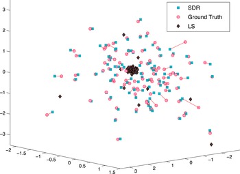
cameras, demonstrating the clustering estimates of the least-squares (LS) method of Brand et al. (Reference Brand, Antone and Teller2004) versus estimates of the relatively stable semidefinite relaxation (SDR) solver of Özyeşil et al. (Reference Özyeşil, Singer and Basri2015). The segments represent the error incurred by the SDR solution compared to the ground truth.

Even though the least-squares methods of Brand et al. (Reference Brand, Antone and Teller2004), Govindu (Reference Govindu2001) and Arie-Nachimson et al. (Reference Arie-Nachimson, Kovalsky, Kemelmacher-Shlizerman, Singer and Basri2012) are computationally very efficient and, for relatively small datasets, produce acceptable location estimates, the quality of their estimates degrades significantly for large, sparse, unordered and noisy datasets, that is, for most of the real datasets studied in the literature. Typically, they tend to produce spurious location estimates that cluster tightly around a small number of points: see Figure 3.2 for an example. This undesired tendency can be intuitively explained by considering the least-squares optimization problem (3.3), for which a clustering part of the solution results in a very small contribution to the cost function, and a few locations, usually corresponding to nodes in the measurement graph having few edges, are separated from the cluster to satisfy the constraints. In order to resolve this difficulty, several different methods have been proposed in the literature. A relatively straightforward starting point, introduced by Özyeşil et al. (Reference Özyeşil, Singer and Basri2015), is to require the locations to satisfy a maximal proximity condition by incorporating ‘repulsion constraints’ of the form
 $\Vert \mathbf{t}_{i}-\mathbf{t}_{j}\Vert \geq c$
, for some fixed
 $c>0$
(taken to be
 $c=1$
in Özyeşil et al.
Reference Özyeşil, Singer and Basri2015), into the least-squares formulation of Brand et al. (Reference Brand, Antone and Teller2004). These non-convex constraints convert the least-squares formulation into the notoriously difficult problem
 $$\begin{eqnarray}\begin{array}{@{}llll@{}} & \displaystyle \underset{\{\mathbf{t}_{i}\}_{i\in V_{t}}\subseteq \mathbb{R}^{d}}{\text{minimize}} & & \displaystyle \mathop{\sum }_{i\sim j}\operatorname{Tr}((\mathbf{t}_{i}-\mathbf{t}_{j})(\mathbf{t}_{i}-\mathbf{t}_{j})^{T}(I-\boldsymbol{\unicode[STIX]{x1D6FE}}_{ij}\boldsymbol{\unicode[STIX]{x1D6FE}}_{ij}^{T}))\\ & \text{subject to} & & \displaystyle \Vert \mathbf{t}_{i}-\mathbf{t}_{j}\Vert _{2}^{2}\geq 1,\quad \text{for all}~(i,j)\in E_{t},\\ & & & \displaystyle \mathop{\sum }_{i}\mathbf{t}_{i}=\mathbf{0}.\end{array}\end{eqnarray}$$
To approximate this computationally difficult problem, Özyeşil et al. (Reference Özyeşil, Singer and Basri2015) first introduce the rank-
 $1$
, positive semidefinite matrix variable
 $T\in \mathbb{R}^{3n\times 3n}$
(where
 $n$
denotes the number of cameras), the
 $ij$
th
 $3\times 3$
block
 $T_{ij}$
of which is given by
 $T_{ij}=\mathbf{t}_{i}\mathbf{t}_{j}^{T}$
. Using
 $T$
, the cost function and the non-convex constraints of (3.4) are given, respectively, by linear functions
 $$\begin{eqnarray}\mathop{\sum }_{i\sim j}\operatorname{Tr}({\mathcal{L}}_{ij}(T)(I-\boldsymbol{\unicode[STIX]{x1D6FE}}_{ij}\boldsymbol{\unicode[STIX]{x1D6FE}}_{ij}^{T}))\end{eqnarray}$$
and
 $\operatorname{Tr}({\mathcal{L}}_{ij}(T))\geq 1$
of
 $T$
, where the operator
 ${\mathcal{L}}_{ij}(\cdot )$
satisfies
 $$\begin{eqnarray}{\mathcal{L}}_{ij}(T)=T_{ii}+T_{jj}-T_{ij}-T_{ji}=(\mathbf{t}_{i}-\mathbf{t}_{j})(\mathbf{t}_{i}-\mathbf{t}_{j})^{T}.\end{eqnarray}$$
As a result of the linearity in
 $T$
of the cost function and the constraints, the non-convexity of (3.4) is fully represented by the non-convex rank-
 $1$
constraint on
 $T$
(note that positive semidefiniteness is a convex constraint). As a result, Özyeşil et al. (Reference Özyeşil, Singer and Basri2015) remove this final non-convex constraint to obtain the semidefinite relaxation formulation given by
 $$\begin{eqnarray}\begin{array}{@{}llll@{}} & \displaystyle \underset{T}{\text{minimize}} & & \displaystyle \mathop{\sum }_{i\sim j}\operatorname{Tr}({\mathcal{L}}_{ij}(T)(I-\boldsymbol{\unicode[STIX]{x1D6FE}}_{ij}\boldsymbol{\unicode[STIX]{x1D6FE}}_{ij}^{T}))\\ & \text{subject to} & & \displaystyle \operatorname{Tr}({\mathcal{L}}_{ij}(T))\geq 1,\quad \text{for all}~i\sim j,\\ & & & \operatorname{Tr}(VT)=0,\\ & & & \,T\succcurlyeq 0.\end{array}\end{eqnarray}$$
The approximate solution
 $\mathbf{t}_{i}$
in (3.4) is obtained to be the
 $i$
th
 $3\times 1$
block of the leading eigenvector of the solution of the SDR (3.6). The tightnessFootnote
6
of this relaxation up to relatively high levels of noise is demonstrated empirically by Özyeşil et al. (Reference Özyeşil, Singer and Basri2015), who also prove a stability of recovery result, which quantifies the amount of distortion in the location estimates to be of the order of the noise present in the pairwise directions, under fairly general assumptions for the noise model. To improve the quality of their location estimates, Özyeşil et al. (Reference Özyeşil, Singer and Basri2015) propose a ‘robust pairwise direction estimation’ method based on the system (3.1), where the
 $\mathbf{y}_{ij}^{k}$
are viewed as noisy samples from the two-dimensional subspace orthogonal to
 $\boldsymbol{\unicode[STIX]{x1D6FE}}_{ij}$
and efficient robust subspace recovery techniques are used to estimate each pairwise direction
 $\boldsymbol{\unicode[STIX]{x1D6FE}}_{ij}$
. Further, and perhaps more importantly, Özyeşil et al. (Reference Özyeşil, Singer and Basri2015) provide a complete characterization of well-posed location recovery from pairwise directionsFootnote
7
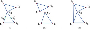
by demonstrating its equivalence to the existing results in the field of parallel rigidity theory. For instance, while camera orientation estimation only requires the connectivity of the measurement graph, connectivity alone is insufficient to make a camera location estimation well-posed; see Figure 3.3 for an example. The complete characterization of well-posed location recovery problems (for arbitrary dimensions
 $d\geq 2$
), via (generically) parallel rigid measurement graphs, is summarized in Theorem 3.1.
(a) A noiseless example of the camera location estimation problem for five locations on a connected graph (we assume noiseless direction measurements between location pairs having an edge), which is not parallel rigid (in
 $\mathbb{R}^{2}$
and
 $\mathbb{R}^{3}$
). Non-uniqueness is demonstrated by two non-congruent location solutions
 $\{\mathbf{t}_{1},\mathbf{t}_{2},\mathbf{t}_{3},\mathbf{t}_{4},\mathbf{t}_{5}\}$
and
 $\{\mathbf{t}_{1},\mathbf{t}_{2},\mathbf{t}_{3},\mathbf{t}_{4}^{\prime },\mathbf{t}_{5}^{\prime }\}$
, each of which can be obtained from the other by an independent rescaling of the solution for one of its maximally parallel rigid components. (b) Maximally parallel rigid components of the formation in (a). (c) A parallel rigid formation (in
 $\mathbb{R}^{2}$
and
 $\mathbb{R}^{3}$
) obtained from the formation in (a) by adding the extra edge
 $(1,4)$
linking its maximally parallel rigid components.

Theorem 3.1. A graph
 $G=(V,E)$
is generically parallel rigid in
 $\mathbb{R}^{d}$
if and only if it contains a non-empty set of edges
 $E^{\prime }\subseteq E$
, with
 $(d-1)|E^{\prime }|=d|V|-(d+1)$
, such that for all subsets
 $E^{\prime \prime }$
of
 $E^{\prime }$
we have
 $$\begin{eqnarray}(d-1)|E^{\prime \prime }|\leq d|V(E^{\prime \prime })|-(d+1),\end{eqnarray}$$
where
 $V(E^{\prime \prime })$
denotes the vertex set of the edges in
 $E^{\prime \prime }$
.
Özyeşil et al. (Reference Özyeşil, Singer and Basri2015) also provide an efficient randomized algorithm for testing well-posedness. Further, they introduce an efficient alternating direction augmented Lagrangian method (ADM) to solve the SDR (3.6), and a distributed algorithm to apply the SDR method to large sets of images.
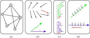
An alternative two-step procedure, studied by Wilson and Snavely (Reference Wilson and Snavely2014), is composed of the detection of outliers among the pairwise direction measurements, via a procedure called 1DSfM, followed by a (non-convex) location estimation method; see Figure 3.4 for a simplified illustration of 1DSfM.
A simplified illustration (courtesy of Wilson and Snavely Reference Wilson and Snavely2014) of outlier detection via 1DSfM. (a) Ground truth camera locations with (potentially noisy) pairwise directions available for camera pairs connected with arrows. (b) Available pairwise directions, with an outlier edge shown in red, and two directions,
 $\hat{i}$
and
 $p$
, for one-dimensional (1D) projections. (c) Projections of pairwise directions onto
 $\hat{i}$
and
 $p$
, resulting in two variants of the minimum feedback arc set problem. (d) Solutions to the 1D problems in (c), depicting the violation (satisfaction) of the 1D constraints by the outlier edge
 $(3,0)$
in the 1D problem induced by
 $\hat{i}$
(
 $p$
), since outlier edges may be consistent with only some of the solutions to the 1D subproblems.

The main idea in the outlier detection step is to project all of the pairwise directions onto a one-dimensional (random) subspace and try to solve the resulting ordering problemFootnote
8
as consistently as possible, from which potential outliers can be identified as having larger inconsistencies. The detection procedure ‘solves’ several of these randomized one-dimensional problems and identifies the outliers as those directions having an inconsistency score larger than a certain value. After removal of outlier direction measurements, the locations are estimated by an unconstrained maximization, using the Levenberg–Marquardt algorithm, of the non-convex cost function
 $\sum _{ij}\hat{\boldsymbol{\unicode[STIX]{x1D6FE}}}_{ij}^{T}(\mathbf{t}_{i}-\mathbf{t}_{j})/\Vert \mathbf{t}_{i}-\mathbf{t}_{j}\Vert$
that measures the alignment of the pairwise directions
 $(\mathbf{t}_{i}-\mathbf{t}_{j})/\Vert \mathbf{t}_{i}-\mathbf{t}_{j}\Vert$
with their ‘cleaned’ estimates
 $\hat{\boldsymbol{\unicode[STIX]{x1D6FE}}}_{ij}$
. Wilson and Snavely (Reference Wilson and Snavely2014) also provide extensive experimental results for large datasets, demonstrating the accuracy and efficiency of their method.
Instead of the systems of equations (3.1) or (3.2), on which the various least-squares methods are based, an alternative approach aiming to prevent the clustering phenomena is to consider the system of equations
 $$\begin{eqnarray}\mathbf{t}_{i}-\mathbf{t}_{j}-\unicode[STIX]{x1D6FC}_{ij}\boldsymbol{\unicode[STIX]{x1D6FE}}_{ij}=\mathbf{0},\end{eqnarray}$$
where
 $\unicode[STIX]{x1D6FC}_{ij}:=\Vert \mathbf{t}_{i}-\mathbf{t}_{j}\Vert$
. Note that if we ignore this defining (non-convex) relation between the
 $\unicode[STIX]{x1D6FC}_{ij}$
and
 $\mathbf{t}_{i}$
, (3.8) turns out to be a linear system in
 $\unicode[STIX]{x1D6FC}_{ij}$
and
 $\mathbf{t}_{i}$
for given
 $\boldsymbol{\unicode[STIX]{x1D6FE}}_{ij}$
. This system forms the basis of the location estimation method used by Tron and Vidal (Reference Tron and Vidal2014), where the cost function is the sum of squares of the errors in (3.8) and the additional constraints
 $\unicode[STIX]{x1D6FC}_{ij}\geq 1$
are used to prevent the trivially collapsing solution
 $\mathbf{t}_{i}\equiv \mathbf{0},\unicode[STIX]{x1D6FC}_{ij}\equiv 0$
. That is, for location estimation, Tron and Vidal (Reference Tron and Vidal2014) solve
 $$\begin{eqnarray}\begin{array}{@{}llll@{}} & \displaystyle \underset{\{\mathbf{t}_{i}\},\{\unicode[STIX]{x1D6FC}_{ij}\}}{\text{minimize}} & & \displaystyle \mathop{\sum }_{i\sim j}\Vert \mathbf{t}_{i}-\mathbf{t}_{j}-\unicode[STIX]{x1D6FC}_{ij}\boldsymbol{\unicode[STIX]{x1D6FE}}_{ij}\Vert ^{2}\\ & \text{subject to} & & \displaystyle \mathop{\sum }_{i}\mathbf{t}_{i}=\mathbf{0};\quad \unicode[STIX]{x1D6FC}_{ij}\geq 1.\end{array}\end{eqnarray}$$
In fact, the main theme in Tron and Vidal (Reference Tron and Vidal2014) is to provide a distributed algorithm for camera motion estimation, that is, joint estimation of orientations and locations. In this respect, they provide a consensus-based three-step algorithm, and local convergence and partial stability results (for the rotational part). The quadratic location estimation method (3.9) is used to obtain an initial set of locations (i.e. it constitutes the second step of their distributed algorithm), and it is then fused with the rotational part to obtain a joint motion estimation method. In terms of the camera location estimation problem with given pairwise directions, the crucial contribution of Tron and Vidal (Reference Tron and Vidal2014) is using (3.8) as an alternative to (3.1) or (3.2), together with the relaxed repulsion constraints
 $\unicode[STIX]{x1D6FC}_{ij}\geq 1$
. As reported by Özyeşil and Singer (Reference Özyeşil and Singer2015), for example, this framework provides location estimates with acceptable quality, which do not tend to cluster for large and noisy datasets, while preserving computational efficiency. A closely related optimization method based on (3.8) and the constraints
 $\unicode[STIX]{x1D6FC}_{ij}\geq 1$
has been introduced by Moulon, Monasse and Marlet (Reference Moulon, Monasse and Marlet2013). The cost function of this method is given by the maximum absolute deviation in the system (3.8).Footnote
9
Moulon et al. (Reference Moulon, Monasse and Marlet2013) also introduce robust rotation and pairwise direction estimation methods. We note, however, that such maximal deviation penalty methods (i.e.
 $\ell _{\infty }$
-norm minimization methods) are highly sensitive to outliers in the pairwise direction estimates.
3.1 Robust convex methods
The existence of a large proportion of outliers among pairwise direction estimates, for example stemming from systematically mismatched features between images as a result of symmetries or ambiguities in the images (see also Section 6.2), manifests itself as large errors in the estimated locations. For some datasets this difficulty may be tamed by preprocessing the pairwise directions for rejection of outliers (as in Wilson and Snavely Reference Wilson and Snavely2014), or by making use of consistencies in locally constructed 3D structures. However, generally applicable efficient algorithms, which are resilient to a large number of outliers and which exhibit provable convergence to globally optimal solutions and admit theoretical guarantees of robustness, are of high value. In this section we will consider two recent algorithms that have some of these desired properties.
The first location estimation algorithm, based on the system (3.8) and closely related to Tron and Vidal (Reference Tron and Vidal2014) and Moulon et al. (Reference Moulon, Monasse and Marlet2013), is given in Özyeşil and Singer (Reference Özyeşil and Singer2015), where this time, instead of using a cost function given as the sum of squared errors (as in Tron and Vidal Reference Tron and Vidal2014) or the maximum error (as in Moulon et al.
Reference Moulon, Monasse and Marlet2013) in the system of equations (3.8), the method minimizes the sum of unsquared errors in (3.8) (hence the name least unsquared deviations (LUD) method) by employing the same relaxed repulsion constraints
 $\unicode[STIX]{x1D6FC}_{ij}\geq 1$
. In other words, the
 $\mathbf{t}_{i}$
are estimated by solving
 $$\begin{eqnarray}\begin{array}{@{}llll@{}} & \displaystyle \underset{\{\mathbf{t}_{i}\},\{\unicode[STIX]{x1D6FC}_{ij}\}}{\text{minimize}} & & \displaystyle \mathop{\sum }_{i\sim j}\Vert \mathbf{t}_{i}-\mathbf{t}_{j}-\unicode[STIX]{x1D6FC}_{ij}\boldsymbol{\unicode[STIX]{x1D6FE}}_{ij}\Vert \\ & \text{subject to} & & \displaystyle \mathop{\sum }_{i}\mathbf{t}_{i}=\mathbf{0};\quad \unicode[STIX]{x1D6FC}_{ij}\geq 1.\end{array}\end{eqnarray}$$
The motivation for this formulation (mainly inspired by compressed sensing methods designed to recover corrupted signals from a minimal set of linear measurements), is to maintain robustness to outliers in the measurements of the pairwise directions
 $\boldsymbol{\unicode[STIX]{x1D6FE}}_{ij}$
. As a convex second-order cone program (SOCP), the LUD solver (3.10) is a computationally efficient location estimator with guaranteed convergence to the globally optimal solution. More importantly, the rather interesting phenomenon of exact location recoveryFootnote
10
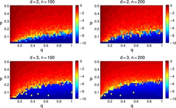
by the LUD method in the presence of sufficiently many exact direction measurements (i.e. sufficiently few outlier direction measurements), the number of which varies with the level of sparsity in the measurement graph and the number of cameras, was first empirically demonstrated by Özyeşil and Singer (Reference Özyeşil and Singer2015) (see Figure 3.5). An efficient iteratively weighted least-squares (IRLS) solver for the LUD problem (3.10) is provided in Özyeşil and Singer (Reference Özyeşil and Singer2015).
Recovery error of the LUD solver (3.10), demonstrating exact recovery regimes in the presence of outliers for dimensions
 $d=2,3$
and number of cameras
 $n=100,200$
. Measurement graphs, with an edge between cameras having pairwise directions, are sampled from the Erdős–Rényi ensemble. Camera locations are i.i.d. Gaussian samples, independent of the measurement graph. The colour intensity of each pixel represents the logarithmic recovery error
 $\log _{10}(\text{NRMSE})$
(see equation (14) in Özyeşil and Singer (Reference Özyeşil and Singer2015) for the definition of the normalized root mean squared error, NRMSE), depending on the probability
 $q$
of the existence of an edge for each pair (
 $x$
-axis), and the probability
 $p$
of each existing edge being an outlier (
 $y$
-axis). NRMSE values are averaged over
 $10$
trials.

Moreover, Özyeşil and Singer (Reference Özyeşil and Singer2015) introduce a (non-convex) direction estimation algorithm based on the system (3.1) (similar to that of Özyeşil et al.
Reference Özyeşil, Singer and Basri2015 but more efficient). The pairwise directions are estimated in a two-step procedure that first produces estimates of unsigned directions
 $\boldsymbol{\unicode[STIX]{x1D6FE}}_{ij}^{0}=b_{ij}\boldsymbol{\unicode[STIX]{x1D6FE}}_{ij}$
, and then computes the initially undetermined signs
 $b_{ij}\in \{-1,+1\}$
via the chirality requirement on the 3D points. In order to maintain robustness to outliers among estimates
 $\hat{\mathbf{y}}_{ij}^{k}$
of
 $\mathbf{y}_{ij}^{k}$
in (3.1) for the estimation of unsigned directions
 $\boldsymbol{\unicode[STIX]{x1D6FE}}_{ij}^{0}$
, Özyeşil and Singer (Reference Özyeşil and Singer2015) consider the following (non-convex) problem:
 $$\begin{eqnarray}\begin{array}{@{}llll@{}} & \displaystyle \underset{\unicode[STIX]{x1D6FE}_{ij}^{0}}{\text{minimize}} & & \displaystyle \mathop{\sum }_{k=1}^{m_{ij}}|(\unicode[STIX]{x1D6FE}_{ij}^{0})^{T}\hat{\mathbf{y}}_{ij}^{k}|\\ & \text{subject to} & & \Vert \unicode[STIX]{x1D6FE}_{ij}^{0}\Vert =1.\end{array}\end{eqnarray}$$
To obtain the estimate
 $\hat{\boldsymbol{\unicode[STIX]{x1D6FE}}}_{ij}^{0}$
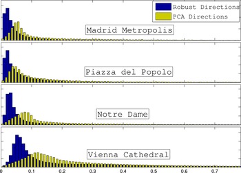
they use a (heuristic) IRLS method, which is not guaranteed to converge to global optima (since the optimization problem (3.11) is not convex). However, they provide empirical evidence for the robustness of the solution to (3.11), while preserving computational efficiency (see Figure 3.6). Finally, Özyeşil and Singer (Reference Özyeşil and Singer2015) demonstrate the high quality and efficiency of the overall method on large datasets from Wilson and Snavely (Reference Wilson and Snavely2014).
Histogram plots of the errors in direction estimates computed by the robust method (3.11) and the PCA method, which replaces the cost function in (3.11) with the sum of squares version
 $\sum _{k=1}^{m_{ij}}((\unicode[STIX]{x1D6FE}_{ij}^{0})^{T}\hat{\mathbf{y}}_{ij}^{k})^{2}$
, for some of the datasets studied in Özyeşil and Singer (Reference Özyeşil and Singer2015). The errors represent the angles between the estimated directions and the corresponding ground truth directions, computed from a sequential SfM method based on Snavely et al. (Reference Snavely, Seitz and Szeliski2006), and provided in Wilson and Snavely (Reference Wilson and Snavely2014). The errors take values in
 $[0,\unicode[STIX]{x1D70B}]$
, but the histograms are restricted to
 $[0,\unicode[STIX]{x1D70B}/4]$
to emphasize the difference in quality for the estimated directions.

The excellent empirical performance of the LUD method has recently inspired the development of a new method for location estimation from pairwise directions called ShapeFit (Hand, Lee and Voroninski Reference Hand, Lee and Voroninski2017). ShapeFit is based on a convex program that minimizes the sum of the unsquared errors in the system (3.2) subject to the constraint
 $\sum _{ij}(\mathbf{t}_{i}-\mathbf{t}_{j})^{T}\boldsymbol{\unicode[STIX]{x1D6FE}}_{ij}=1$
, which fixes the scale and sign of the location estimates, as well as encouraging correlation with the true relative directions. Specifically, the ShapeFit program consists of the following:
 $$\begin{eqnarray}\begin{array}{@{}llll@{}} & \displaystyle \underset{\{\mathbf{t}_{i}\}}{\text{minimize}} & & \displaystyle \mathop{\sum }_{i\sim j}\Vert (I-\boldsymbol{\unicode[STIX]{x1D6FE}}_{ij}\boldsymbol{\unicode[STIX]{x1D6FE}}_{ij}^{T})(\mathbf{t}_{i}-\mathbf{t}_{j})\Vert _{2}\\ & \text{subject to} & & \displaystyle \mathop{\sum }_{i}\mathbf{t}_{i}=\mathbf{0},\quad \mathop{\sum }_{i\sim j}(\mathbf{t}_{i}-\mathbf{t}_{j})^{T}\unicode[STIX]{x1D6FE}_{ij}=1.\end{array}\end{eqnarray}$$
Similar to the LUD method of Özyeşil and Singer (Reference Özyeşil and Singer2015), the motivation behind the cost function of ShapeFit is to improve robustness to outliers among the pairwise direction measurements. Also, ShapeFit is amenable to theoretical analysis, and the results of Hand et al. (Reference Hand, Lee and Voroninski2017) provide the first rigorous results guaranteeing exact location recovery from corrupted relative direction observations. More concretely, Theorem 1 in Hand et al. (Reference Hand, Lee and Voroninski2017) considers a high-dimensional version of the location recovery problem (i.e.
 $\mathbf{t}_{i}\in \mathbb{R}^{d}$
for sufficiently large
 $d$
) and proves exact location recovery with high probability for i.i.d. Gaussian locations in the presence of a measurement graph sampled from an Erdős–Rényi ensemble, for which at most a constant fraction of direction measurements for any particular location is arbitrarily corrupted. For the same setup, with the exception of requiring the fraction of corrupted directions measurements for any particular location to be at most a constant, up to poly-logarithmic factors, Theorem 2 of Hand et al. (Reference Hand, Lee and Voroninski2017) proves exact location recovery for the physically relevant case
 $d=3$
. The physically relevant theorem is as follows.
Theorem 3.2. There exists
 $n_{0}\in \mathbb{N}$
and
 $c\in \mathbb{R}$
such that the following holds for all
 $n\geq n_{0}$
. Let the measurement graph
 $G([n],E)$
be drawn from the Erdős–Rényi ensemble
 $G(n,p)$
for some
 $p=\unicode[STIX]{x1D6FA}(n^{-1/5}\log ^{3/5}n)$
. Let
 $\mathbf{t}_{1}^{(0)},\ldots ,\mathbf{t}_{n}^{(0)}\in \mathbb{R}^{3}$
denote the ground truth location, where
 $\mathbf{t}_{i}^{(0)}\sim {\mathcal{N}}(0,I_{3\times 3})$
are i.i.d. independent from
 $G$
. There exists
 $\unicode[STIX]{x1D6FE}=\unicode[STIX]{x1D6FA}(p^{5}/\log ^{3}n)$
and an event of probability at least
 $1-1/n^{4}$
on which the following holds.
For arbitrary subgraphs
 $E_{b}\subset E$
satisfying that, for any vertex
 $i$
, the number of edges emanating from
 $i$
which are corrupted is bounded by
 $\unicode[STIX]{x1D6FE}n$
, and for arbitrary pairwise direction corruptions
 $\mathbf{v}_{ij}\in \mathbb{S}^{2}$
for
 $(i,j)\in E_{b}$
, the convex program (3.12) has a unique minimizer equal to
 $$\begin{eqnarray}\{\unicode[STIX]{x1D6FC}(\mathbf{t}_{i}^{(0)}-\bar{\mathbf{t}}^{(0)})\}_{i\in [n]}\end{eqnarray}$$
for some positive
 $\unicode[STIX]{x1D6FC}$
and for
 $$\begin{eqnarray}\bar{\mathbf{t}}^{(0)}=\displaystyle \frac{1}{n}\mathop{\sum }_{i\in [n]}\mathbf{t}^{(0)}.\end{eqnarray}$$
Both of these theorems follow from the much more general Theorem 3 in Hand et al. (Reference Hand, Lee and Voroninski2017), which establishes that ShapeFit succeeds in recovering locations from corrupted relative directions under broad deterministic assumptions on the measurement graph
 $G$
and the geometry of locations. Note that the setting for ShapeFit theorems is that of robust statistics, in that the corruptions are assumed to be adversarial, and thus for a fixed set of locations and observations the theorem above establishes that ShapeFit succeeds uniformly in the data corruptions, provided there is a bound on the number of corrupted edges emanating from any particular location node.
The proof strategy for ShapeFit theorems is a direct analysis of the optimality conditions of the convex objective function, which relies on the combinatorial propagation of various local geometric properties. For instance, one such property is that if a collection of triangles share the same base and the locations opposite the base are sufficiently ‘well-distributed’, then an infinitesimal rotation of the base induces infinitesimal rotations in edges of many of the triangles. It is then ensured that for each corrupted edge
 $(k,l)$
, one can find sufficiently many triangles in the observation graph with two good edges and base
 $(k,l)$
, with locations at the opposing vertices being ‘well-distributed’. However, the full proof is more nuanced, and needs the constraints of the ShapeFit program. The other important local property is that for a tetrahedron in
 $\mathbb{R}^{3}$
with well-distributed vertices, any discordant parallel deviations on two of its disjoint edges induce enough infinitesimal rotational motion on some other edge of the tetrahedron. Combinatorial propagation is then handled separately in two regimes of the relative balance of parallel deviations on the good and corrupted subgraphs.
Hand et al. (Reference Hand, Lee and Voroninski2017) also provide empirical evidence supporting the main theoretical results about ShapeFit. These results demonstrate that the ShapeFit method can tolerate a larger fraction of pure outliers as compared to the LUD estimator for exact location recovery from randomly generated data, whereas in a mixed noise setting the LUD solver has a smoother change in its recovery performance (as corruption probability varies) and lower (higher) recovery errors in the high (low) corruption probability regime. More importantly, Goldstein, Hand, Lee, Voroninski and Soatto (Reference Goldstein, Hand, Lee, Voroninski and Soatto2016) test ShapeFit empirically on a dozen standard ‘photo tourism’ datasets. They introduce a novel numerical framework for solving programs like ShapeFit and LUD, leading to an ADMM-based approach called ShapeKick, which solves location recovery problems orders of magnitude faster than competing methods. Goldstein et al. (Reference Goldstein, Hand, Lee, Voroninski and Soatto2016) provide a comparative study, with respect to competing methods such as LUD and 1DSfM, demonstrating the accuracy and high efficiency of ShapeFit and ShapeKick.
3.2 Other methods
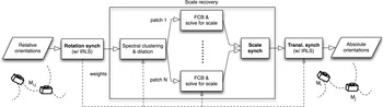
One of the methods deviating from the generic recipe considered above is studied in Govindu (Reference Govindu2004). In this method, camera orientations and locations are jointly estimated using an iterative averaging method on the Lie algebra of the group of Euclidean motions. Although Govindu’s paper lacks theoretical and strong empirical stability guarantees, its approach is an efficient alternative for joint motion estimation in the low-noise regime. Another recent method slightly deviating from the generic recipe has been introduced by Arrigoni, Fusiello and Rossi (Reference Arrigoni, Fusiello and Rossi2016). Called the group synchronization pipeline (GSP), this method is based on a three-step estimation, via (robust) synchronization, of the camera orientations in
 $\text{SO}(3)$
, baseline scalesFootnote
11
(i.e.
 $\unicode[STIX]{x1D6FC}_{ij}$
in (3.8)) in
 $\mathbb{R}^{+}$
, and the camera locations in
 $\mathbb{R}^{3}$
; see Figure 3.7 for a depiction of the GSP. The term synchronization here refers to a class of methods aiming to (globally) estimate a set of mathematical group elements
 $\{g_{i}\}$
from a potentially noisy and incomplete set of observations of their pairwise ratiosFootnote
12
 $g_{i}^{-1}g_{j}$
. The term was originally coined by Singer (Reference Singer2011), who studied the problem of estimating planar rotations from measurements of their pairwise ratios. As an example of a synchronization problem, in order to estimate the camera orientations
 $R_{i}\in \text{SO}(3)$
(represented as
 $3\times 3$
orthonormal matrices with determinant one) from measurements
 $\hat{R}_{ij}$
of their ratios
 $R_{ij}=R_{i}^{T}R_{j}$
, we can consider the problem
 $$\begin{eqnarray}\begin{array}{@{}llll@{}} & \displaystyle \underset{\{R_{i}\}}{\text{minimize}} & & \displaystyle \mathop{\sum }_{i\sim j}\Vert R_{i}-R_{j}\hat{R}_{ij}^{T}\Vert _{F}^{2}\\ & \text{subject to} & & \{R_{i}\}\subseteq \text{SO}(3),\end{array}\end{eqnarray}$$
which is a difficult non-convex problem due to the set of constraints. However, the problem (3.13) (and its variations using robust cost functions instead of the sum of squared deviations in (3.13)) has been shown in the literature to admit high-quality approximations via convex relaxations and spectral methods; see for example Arie-Nachimson et al. (Reference Arie-Nachimson, Kovalsky, Kemelmacher-Shlizerman, Singer and Basri2012), Özyeşil et al. (Reference Özyeşil, Singer and Basri2015), Chatterjee and Govindu (Reference Chatterjee and Govindu2013), Wang and Singer (Reference Wang and Singer2013) and Cucuringu, Singer and Cowburn (Reference Cucuringu, Singer and Cowburn2012). The estimates of Arrigoni et al.’s first two steps are fused into the available data in the last step to produce the final location estimates via an iteratively reweighted least-squares (IRLS) solver for the resulting linear system of equations. The high quality of the overall approach in Arrigoni et al. (Reference Arrigoni, Fusiello and Rossi2016) is empirically presented on large datasets. Instead of relying solely on relations between pairs of cameras, Jiang, Cui and Tan (Reference Jiang, Cui and Tan2013) introduce a linear method based on minimizing the error in a set of geometrical relations among triplets of cameras (for details see Jiang et al. Reference Jiang, Cui and Tan2013, Section 4.1), which requires knowledge of ratios of baseline lengths computed from locally reconstructed scene points. Furthermore, to improve the quality of the location estimates in the presence of outliers among pairwise measurements, Jiang et al. (Reference Jiang, Cui and Tan2013) employ various heuristic outlier rejection techniques. We note that although this linear method has some desirable properties, such as being applicable to collinear motion, computational efficiency, etc., it is rather sensitive to outlier measurements, and hence the outlier rejection techniques proposed by Jiang et al. are of critical importance to maintaining stability. Another alternative location estimation approach, introduced by Sinha, Steedly and Szeliski (Reference Sinha, Steedly and Szeliski2010), which aims to tame the instability resulting from unknown scales, uses two-view reconstructions for camera pairs. The main idea is to obtain relative scales and translation between the two-view reconstructions sharing sufficiently many 3D points, and to use this information in the camera location and scale estimation. The pipeline in Sinha et al. (Reference Sinha, Steedly and Szeliski2010) also produces an initial 3D structure estimate, which, together with its motion estimate, can be used to initialize reprojection error minimization algorithms for final structural refinement.
Depiction of the group synchronization pipeline (GSP) in Arrigoni et al. (Reference Arrigoni, Fusiello and Rossi2016), including the group synchronization stages in bold. Figure courtesy of Arrigoni et al. (Reference Arrigoni, Fusiello and Rossi2016).

4 Structure estimation
This section considers some of the key contributions in the literature mainly concerning the 3D structure estimation part of the SfM problem. These works have a relatively wide spectrum, including incremental and global methods, joint structure and motion estimation methods, and methods specifically targeting very large-scale SfM. Typically, the number of 3D structure points in SfM is much greater than the number of corresponding cameras: for an unordered collection of about
 $10^{3}$
cameras, for example, it is reasonable to expect of the order of
 $10^{6}$
structure points. Therefore, the fundamental challenge is the efficient processing of the given data in a consistent way, while maintaining robustness to noise in the data.
The primary algorithms for joint refinement of the 3D structure, the camera motion and possibly also the intrinsic camera parameters (also called the camera calibration parameters) are known as bundle adjustment methods. As indicated in Triggs et al.’s excellent survey of bundle adjustment (see Triggs et al. Reference Triggs, McLauchlan, Hartley and Fitzgibbon2000, Figure 9), their origin can be traced back to the works of Gauss and Legendre on least-squares estimation in the late eighteenth and early nineteenth centuries. However, in this section we will focus on more recent developments, and more generally on structure estimation methods that mainly aim to facilitate the processing of large unordered sets of images.
Triggs et al. (Reference Triggs, McLauchlan, Hartley and Fitzgibbon2000) discussed several different aspects of bundle adjustment, including the basic projection model and problem parametrization, error modelling and the choice of cost function, the main types of numerical optimization algorithms, the sparse problem structure as induced by the network of variables (and how to exploit it to improve reconstruction accuracy), gauge invariance, and quality control to detect outliers and characterize the overall accuracy of the estimated parameters. They presented the projection model and the problem parametrization in a generalized, rather abstract framework to incorporate various scene models (e.g. relatively simple isolated 3D features made up of points, lines or planes, or more complicated models involving dynamics, photometry or complex objects linked by constraints) and camera models (e.g. perspective, affine or orthographic projections, or less frequently encountered models such as rational polynomial cameras). To define a feature prediction error (also sometimes referred to as the total reprojection error), Triggs et al. (Reference Triggs, McLauchlan, Hartley and Fitzgibbon2000) considered a simple scene model comprising static, individual (abstract) 3D features
 $\mathbf{X}_{j}$
imaged by a set of cameras corresponding to the position and intrinsic calibration parameters
 $\mathbf{C}_{i}$
. In this framework we are given noisy measurements
 $\bar{\mathbf{x}}_{ij}$
of the image features
 $\mathbf{x}_{ij}$
representing the true image of features
 $\mathbf{X}_{j}$
in image
 $i$
, that are assumed to satisfy a predictive model given by
 $\mathbf{x}_{ij}=\mathbf{x}(\mathbf{C}_{i},\mathbf{X}_{j})$
. The feature prediction errors for the measurements
 $\bar{\mathbf{x}}_{ij}$
are then defined by
 $$\begin{eqnarray}\unicode[STIX]{x1D6E5}\mathbf{x}_{ij}(\mathbf{C}_{i},\mathbf{X}_{j}):=\bar{\mathbf{x}}_{ij}-\mathbf{x}(\mathbf{C}_{i},\mathbf{X}_{j}).\end{eqnarray}$$
To reconstruct the scene, a measure of these prediction errors is minimized, where bundle adjustment corresponds to the refinement part of this optimization, and requires an initial set of estimates for the camera and structure parameters (e.g. computed using a simpler technique). In summary, as noted by Triggs et al. (Reference Triggs, McLauchlan, Hartley and Fitzgibbon2000, p. 302), bundle adjustment ‘is essentially a matter of optimizing a complicated nonlinear cost function (the total prediction error) over a large nonlinear parameter space (the scene and camera parameters)’, the accuracy of which is highly dependent on the initial estimates of camera and structure parameters (explaining, for example, the wide variety of initial motion estimation methods), and on the choice of the parametrization of the parameter space; for a more detailed discussion see Triggs et al. (Reference Triggs, McLauchlan, Hartley and Fitzgibbon2000, Section 2.2). Moreover, Triggs et al. studied the choice of the cost function defining the measure of the errors in (4.1), reaching the main conclusion that robust, statistically based error metrics allowing the presence of outliers in the measurements are appropriate choices. They discussed three main categories of algorithms for the numerical optimization of the chosen cost function in detail, namely the second-order Newton-style methods, first-order methods (demonstrating linear asymptotic convergence) and the sequential methods incorporating a series of observations one by one (as opposed to solving for the whole system globally). For second-order methods, which have fast asymptotic convergence rates but relatively high costs per iteration, they explored several different techniques for improving efficiency, mainly exploiting the sparsity patterns of the Hessian of the cost function. They also discussed various first-order methods, including the simple gradient descent, linear and non-linear Gauss–Seidel methods and Krylov subspace methods. For the third category of sequential algorithms, they considered low-rank update techniques for updating the Hessian and various filtering techniques. Triggs et al. (Reference Triggs, McLauchlan, Hartley and Fitzgibbon2000) also provided methods for handling theoretical and algorithmic difficulties that arise from several gauge symmetries involved in the problem, and (essentially) concluded with various analytical and heuristic techniques for quality control, that are used to maintain algorithmic stability and robustness to outlier measurements, and to characterize the overall accuracy of the estimates.
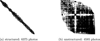
A relatively recent work on large-scale bundle adjustment (for tens of thousands of images) is that of Agarwal, Snavely, Seitz and Szeliski (Reference Agarwal, Snavely, Seitz and Szeliski2010). The main challenge identified by Agarwal et al. (Reference Agarwal, Snavely, Seitz and Szeliski2010) is the low sparsity levels (i.e. relatively high density) present in the connectivity graphsFootnote 13 of unstructured sets of images, such as community photo collections, as opposed to the higher sparsity of the structured image sets (e.g. street-level datasets such as images captured from a moving truck); for an example see Figure 4.1. The decrease in sparsity drastically increases the computational cost of the sparse factorization methods employed in classical bundle adjustment methods. To address this difficulty, the inexact (truncated) Newton-type algorithm introduced by Agarwal et al. (Reference Agarwal, Snavely, Seitz and Szeliski2010) makes use of conjugate gradients for the Newton step computation combined with various preconditioners. In more detail, they consider a non-linear least-squaresFootnote 14 bundle adjustment problem stated (abstractly) as
 $$\begin{eqnarray}\underset{\mathbf{x}}{\text{minimize}}~~\displaystyle \frac{1}{2}\Vert \mathbf{F}(\mathbf{x})\Vert ^{2},\end{eqnarray}$$
where
 $\mathbf{x}\in \mathbb{R}^{p}$
,
 $\mathbf{F}:\mathbb{R}^{p}\rightarrow \mathbb{R}^{q}$
. Let
 $J(\mathbf{x})\in \mathbb{R}^{q\times p}$
denote the Jacobian of
 $\mathbf{F}$
at
 $\mathbf{x}$
and let
 $$\begin{eqnarray}\mathbf{g}(\mathbf{x}):=\unicode[STIX]{x1D6FB}\displaystyle \frac{1}{2}\Vert \mathbf{F}(\mathbf{x})\Vert ^{2}=J(\mathbf{x})^{T}\mathbf{F}(\mathbf{x}).\end{eqnarray}$$
Agarwal et al. (Reference Agarwal, Snavely, Seitz and Szeliski2010) consider a Levenberg–Marquardt (LM) approach to solving (4.2), which, to compute the update
 $\mathbf{x}\rightarrow \mathbf{x}+\unicode[STIX]{x1D6E5}\mathbf{x}$
at each iteration (while ensuring convergence by controlling the step size
 $\Vert \unicode[STIX]{x1D6E5}\mathbf{x}\Vert$
), solves the regularized least-squares problem
 $$\begin{eqnarray}\underset{\unicode[STIX]{x1D6E5}\mathbf{x}}{\text{minimize}}~~\displaystyle \frac{1}{2}(\Vert J(\mathbf{x})\unicode[STIX]{x1D6E5}\mathbf{x}+\mathbf{F}(\mathbf{x})\Vert ^{2}+\unicode[STIX]{x1D707}\Vert D(\mathbf{x})\unicode[STIX]{x1D6E5}\mathbf{x}\Vert ^{2}),\end{eqnarray}$$
where
 $D(\mathbf{x})$
is a non-negative diagonal matrix, for example, given by
 $$\begin{eqnarray}D(\mathbf{x})_{ii}=\sqrt{\mathop{\sum }_{j}J(\mathbf{x})_{ji}^{2}},\end{eqnarray}$$
and
 $\unicode[STIX]{x1D707}>0$
determines the regularization strength. Note that if the regularized Hessian
 $H_{\unicode[STIX]{x1D707}}(\mathbf{x}):=J(\mathbf{x})^{T}J(\mathbf{x})+\unicode[STIX]{x1D707}D(\mathbf{x})^{T}D(\mathbf{x})$
is positive definite, we can solve (4.3) via the normal equations
 $$\begin{eqnarray}H_{\unicode[STIX]{x1D707}}(\mathbf{x})\unicode[STIX]{x1D6E5}\mathbf{x}=-\mathbf{g}(\mathbf{x}).\end{eqnarray}$$
Here, the crucial point is that
 $H_{\unicode[STIX]{x1D707}}(\mathbf{x})$
usually turns out to have a special block structure induced by the sparsity pattern of the bundle adjustment problem, which simplifies the solution to (4.4). For instance, assuming that the components of
 $\mathbf{F}(\cdot )$
only depend on a single camera or a single 3D feature, which is usually the case, then we get
 $$\begin{eqnarray}H_{\unicode[STIX]{x1D707}}=\left[\begin{array}{@{}cc@{}}B & E\\ E^{T} & C\end{array}\right]\!,\end{eqnarray}$$
where
 $B$
and
 $C$
are block diagonal (with blocks of size
 ${<}10$
, and hence can be efficiently inverted), and
 $E$
is block sparse. Therefore, by also considering the appropriate block representations
 $\unicode[STIX]{x1D6E5}\mathbf{x}=[\unicode[STIX]{x1D6E5}\mathbf{y},\unicode[STIX]{x1D6E5}\mathbf{z}]$
and
 $-g=[v,w]$
, and solving for
 $\unicode[STIX]{x1D6E5}\mathbf{z}$
by
 $\unicode[STIX]{x1D6E5}\mathbf{z}=C^{-1}(w-E^{T}\unicode[STIX]{x1D6E5}\mathbf{y})$
, we obtain
 $$\begin{eqnarray}[B-EC^{-1}E^{T}]\unicode[STIX]{x1D6E5}\mathbf{y}=v-EC^{-1}w.\end{eqnarray}$$
Here the Schur complement
 $S$
of
 $C$
in
 $H_{\unicode[STIX]{x1D707}}$
given by
 $S=B-EC^{-1}E^{T}$
, and known as the reduced camera matrix, has a block sparse structure with a non-zero
 $ij$
th block if and only if the
 $i$
th and the
 $j$
th images have at least one common feature point. As noted by Agarwal et al. (Reference Agarwal, Snavely, Seitz and Szeliski2010), computationally speaking, the reduction of (4.4) to (4.6), via the Schur complement trick given above, allows us to obtain a solution to (4.4) using classical Cholesky factorization methods (that do not exploit the sparsity pattern in
 $S$
) in
 $O(n^{2})$
space and
 $O(n^{3})$
time complexity, where
 $n$
denotes the number of cameras. These computational costs become prohibitive for large datasets, and hence an alternative is to use decomposition algorithms that exploit the sparsity in
 $S$
. However, as the datasets grow and the level and simplicity of sparsity in
 $S$
decreases (as argued by Agarwal et al.
Reference Agarwal, Snavely, Seitz and Szeliski2010 for the case of community photo collections), even the construction and storage of
 $S$
becomes computationally challenging. As a result, instead of trying to solve (4.3) exactly, for example by using the Schur complement trick discussed above, they propose using an inexact Newton method based on an approximate iterative linear system solver, such as conjugate gradient (CG), possessing a termination rule given by
 $$\begin{eqnarray}\Vert H_{\unicode[STIX]{x1D707}}(\mathbf{x})\unicode[STIX]{x1D6E5}\mathbf{x}+\mathbf{g}(\mathbf{x})\Vert \leq \unicode[STIX]{x1D702}_{k}\Vert \mathbf{g}(\mathbf{x})\Vert ,\end{eqnarray}$$
where
 $0<\unicode[STIX]{x1D702}_{k}\leq \unicode[STIX]{x1D702}_{0}<1$
,
 $k$
denoting the LM iteration number, is used as a forcing sequence to guarantee convergence. Further, Agarwal et al. (Reference Agarwal, Snavely, Seitz and Szeliski2010) consider several preconditioners
 $M$
for which the matrix
 $M^{-1}H_{\unicode[STIX]{x1D707}}(\mathbf{x})$
of the equivalent linear system
 $M^{-1}H_{\unicode[STIX]{x1D707}}(\mathbf{x})\unicode[STIX]{x1D6E5}\mathbf{x}=-M^{-1}\mathbf{g}(\mathbf{x})$
has reduced condition number, which therefore improves the CG convergence rate. Agarwal et al. (Reference Agarwal, Snavely, Seitz and Szeliski2010) conclude their paper by extensively comparing the experimental stability and efficiency of their preconditioned CG method with other preconditioners, and with the classical methods factoring the Schur complement, obtaining significant improvements in accuracy and efficiency, in both time and memory, using their proposed algorithm.
Sparsity patterns of the adjacency matrices of the connectivity graphs for two sets of images: (a) a structured set of photos (taken from a moving truck), and (b) an unstructured collection of community photos corresponding to a search for the term ‘Dubrovnik’ in Flickr. Figure courtesy of Agarwal et al. (Reference Agarwal, Snavely, Seitz and Szeliski2010).

For large, unordered and hence computationally challenging datasets, Crandall, Owens, Snavely and Huttenlocher (Reference Crandall, Owens, Snavely and Huttenlocher2011) have introduced an alternative global approach, whose formulation is based on first computing a coarse initial solution via a hybrid discrete-continuous optimization, using discrete belief propagation (BP) within a Markov random field (MRF) formulation of pairwise camera and camera-point constraints to estimate camera parameters and a continuous LM improvement, and then refining the resulting solution with classical bundle adjustment. This method also employs various alternative sources of data such as noisy geotags and vanishing point estimates extracted from images. More concretely, the method first solves for camera orientations by minimizing a robust cost function of the error in the (classical) pairwise rotational consistency equations (i.e. the equations
 $R_{ij}=R_{i}^{T}R_{j}$
, for which we have access to noisy measurements of some of the relative rotations
 $R_{ij}$
), using a mixture of BP (on a discretization of the 3D sphere) and LM refinement. Having solved for the orientations
 $R_{i}$
, the joint estimation of the camera locations and structure points is based on the minimization of (a robust cost function of) the total angles of deviation between pairwise translations
 $\mathbf{t}_{i}-\mathbf{t}_{j}$
and pairwise directions
 $\boldsymbol{\unicode[STIX]{x1D6FE}}_{ij}$
(see e.g. (3.2)) and between 3D point-to-camera displacements (given by
 $\mathbf{P}_{k}-\mathbf{t}_{i}$
between the
 $k$
th 3D point
 $\mathbf{P}_{k}$
and camera
 $i$
) and ‘ray directions’ (given in the noiseless case by
 $\mathbf{r}_{ik}=R_{i}^{T}K_{i}^{-1}\mathbf{p}_{ik}$
, for the known intrinsic matrix
 $K_{i}$
of camera
 $i$
, and the projective measurement
 $\mathbf{p}_{ik}$
of
 $\mathbf{P}_{k}$
by camera
 $i$
). This minimization is again performed with a hybrid BP and LM method. Even though, in principle, such non-convex methods are highly sensitive to initial points, and hence susceptible to local minima, Crandall et al. (Reference Crandall, Owens, Snavely and Huttenlocher2011) have been able to improve its sensitivity and obtain, as empirically demonstrated, high-quality reconstructions by also making use of external, additional sources of information like geotags and vanishing points. Further, the parallelizable structure of the methods in Crandall et al. (Reference Crandall, Owens, Snavely and Huttenlocher2011) allows the realization of significant improvements in computational efficiency.
A relatively popular main approach to handling challenging datasets is to employ sequential processing of the available images, that is, to incorporate the images one by one, or in small groups, to obtain a solution for the whole set based on a ‘core solution’ computed from a small subset of the available data. A systematic method of this sequential type was introduced by Snavely, Seitz and Szeliski (Reference Snavely, Seitz and Szeliski2008b
), whose main idea was to identify a small subset of the available images, called the skeletal set, by first estimating the accuracy of pairwise reconstructions of overlapping images and then extracting a subset whose reconstruction accuracy approximates that of the total set. The remaining images are then incorporated by position estimation, and a final bundle adjustment can be used to improve accuracy. The computation of the skeletal set is rather complicated,Footnote
15
but the main idea is to identify a (directed) measure of proximity between cameras, identified as nodes of the image graph, given by the (translational) uncertainty in the pairwise reconstruction (obtained by fixing the location and orientation of one of the cameras in the pair and then repeating it for the other one) as quantified by the trace of the covariance matrix given by the translational part of the inverse of the Hessian of the reduced camera system (4.6) (i.e. the Schur complement
 $S=B-EC^{-1}E^{T}$
for the camera pair); see Figure 4.2 for a simplified depiction. The skeletal set problem is to identify the smallest subset of cameras, subject to the constraint that the distance (length of the shortest path, as defined by the total uncertainty of the path) between any pair of cameras in the (directed) subgraph induced by this subset is at most
 $t$
times longer than their distance in the original digraph (induced by the set of all cameras). The factor
 $t$
is called the stretch factor, and controls the amount of additional uncertainty introduced between camera pairs by removing cameras from the available dataset. Also, the skeletal set is required to satisfy the constraint of being uniquely realizable, which is modelled and controlled via a structure that they call the pair graph. Unfortunately, this problem (even if we ignore the additional realizability constraint), known as computing a minimum
 $t$
-spanner for the digraph of camera pairs, is NP-complete for general graphs. Hence, Snavely et al. (Reference Snavely, Seitz and Szeliski2008b
, Section 4) employ a two-step heuristic approximation to compute the skeletal set. The empirical results provided by Snavely et al. (Reference Snavely, Seitz and Szeliski2008b
) demonstrate a significant increase in overall SfM efficiency, and the accuracy of the reconstructed structure as compared to applying existing SfM techniques to the full set of images.
A toy example of the construction of the skeletal graph in Snavely et al. (Reference Snavely, Seitz and Szeliski2008b
). (a) Nodes of the image graph represent images and its edges represent pairwise reconstructions (in fact the image graph is directed, and each connected pair has two directed edges; only one is shown for simplicity). Each (directed) edge
 $(I,J)$
is endowed with a covariance matrix
 $C_{IJ}$
representing the uncertainty in image
 $J$
relative to
 $I$
. (b) Relative uncertainty between the nodes
 $P$
and
 $Q$
is quantified by the trace of the covariance matrices (ellipses) chained up along the shortest path (arrows) between the nodes. (c) Removing an edge lengthens the shortest path, resulting in larger estimated covariance (larger ellipses). (d) The solid edges are those of the skeletal graph, while the dotted edges have been removed. The black (interior) nodes form the skeletal set, and are to be reconstructed first, while the grey (leaf) nodes are added to it using position estimation. The skeletal graph is constructed by trying to minimize the number of interior nodes, while bounding the increase in relative uncertainty between all pairs of nodes in the original graph in (a). Figure courtesy of Snavely et al. (Reference Snavely, Seitz and Szeliski2008b
).

Another incremental method, similar in spirit to Snavely et al. (Reference Snavely, Seitz and Szeliski2008b ), has been studied by Havlena, Torii and Pajdla (Reference Havlena, Torii and Pajdla2010). Their main idea for improving the efficiency of the overall SfM pipeline is to identify a small subset of input images by computing an approximate minimally connected dominating set, for which each of the remaining images has significant overlaps with at least one of the images in this set, and to employ task prioritization to promote easier image matching. Moreover, instead of computing actual image matchings, which is computationally prohibitive for thousands of cameras if performed on each pair of images, they employ fast image indexing techniques based on large image vocabularies to measure visual overlaps between images. To identify image similarities, they use a ‘bag-of-words approach’ (Havlena et al. Reference Havlena, Torii and Pajdla2010, Section 2.1). The computation of a minimally connected dominating set for the induced (unweighted, undirected) graph, defined as a minimum-sized connected subgraph, of which each vertex of the original graph is either a member or a neighbour, is in general NP-hard. Hence, they use a polynomial-time approximation algorithm from the literature for this task (Havlena et al. Reference Havlena, Torii and Pajdla2010, Algorithm 1). For the 3D structure, they make use of the atomic 3D models from image triplets approach of Havlena, Torii, Knopp and Pajdla (Reference Havlena, Torii, Knopp and Pajdla2009), and grow the structure by using a prioritization queue, which orders the different tasks of either creating a new atomic 3D model or incorporating one image into a given 3D model (Havlena et al. Reference Havlena, Torii and Pajdla2010, Section 3). They conclude with various experimental results, including image sets captured by omnidirectional cameras, demonstrating the efficiency and accuracy of their approach.
A notable work of an incremental nature is the photo tourism system of Snavely et al. (Reference Snavely, Seitz and Szeliski2006), which was also discussed in Section 1. Although the SfM part of their paper is primarily based on a rather classical, generic type of sequential incorporation of images, one by one, using the sparse bundle adjustment algorithm of Lourakis and Argyros (Reference Lourakis and Argyros2009), it provides a very rich set of tools for content exploration, such as 3D scene visualization, object-based photo browsing, geolocation from images, or object annotation; see Figure 4.3 for a simplified illustration of the photo tourism system.
Photo tourism system of Snavely et al. (Reference Snavely, Seitz and Szeliski2006): (a) An unstructured collection of images, e.g. downloaded from the Internet, as input to the system. (b) SfM step composed of camera motion estimation and 3D structure reconstruction. (c) Content exploration, such as 3D scene visualization, object-based photo browsing, geolocation from images, object annotation, etc. Figure courtesy of Snavely et al. (Reference Snavely, Seitz and Szeliski2006).

For sequential SfM, Snavely et al. identify an initial pair of cameras sharing a large set of feature points, which also have a known baseline to improve the accuracy of the reconstructed initial 3D points. The selection criterion for a new camera is to have a maximal number of feature points that correspond to the already reconstructed 3D points. This iterative procedure is repeated until no remaining camera observes any reconstructed 3D point; for additional details, such as detection of outlier tracks, geo-registration, and specific algorithms used, see Snavely et al. (Reference Snavely, Seitz and Szeliski2006, Section 4). Even though the overall computational cost of the proposed SfM pipeline can be fairly high for relatively large datasets,Footnote 16 it provides an accurate alternative to SfM, and more importantly, the rich set of tools it provides for content exploration strikingly demonstrates the wide range of applicability and usefulness of SfM.
Yet another remarkable SfM approach for processing large (specifically city-scale) unordered datasets has been introduced by Agarwal, Snavely, Simon, Seitz and Szeliski (Reference Agarwal, Snavely, Simon, Seitz and Szeliski2009). The key paradigm they explore is the parallel processing of the various stages in SfM, and hence its main contributions are the identification of challenges and introduction of solutions in the parallelization of the SfM pipeline. In its multi-stage image matching method, where each stage consists of a proposal step (of possible image pairs sharing common features) and a verification step, they employ several different techniques, such as vocabulary tree-based whole-image similarity and query expansion, while simultaneously controlling the computational efficiency of the distributed framework; for details see Agarwal et al. (Reference Agarwal, Snavely, Simon, Seitz and Szeliski2009, Sections 2.2, 2.3). For the SfM part, they use the skeletal set method of Snavely et al. (Reference Snavely, Seitz and Szeliski2008b ) to reduce the computational cost significantly, and they compute the initial camera motion and 3D structure for the skeletal set via the sequential SfM method of Snavely et al. (Reference Snavely, Seitz and Szeliski2006). To improve upon the computed motion and structure, they perform bundle adjustment, where, depending on the size of the problem, they choose between a preconditioned CG method (as in Agarwal et al. Reference Agarwal, Snavely, Seitz and Szeliski2010) for large datasets, and an exact step LM algorithm for smaller datasets. Finally, Agarwal et al. (Reference Agarwal, Snavely, Simon, Seitz and Szeliski2009) demonstrate the accuracy and efficiency of their overall approach via extensive experimental results for various city-scale datasets.
Interestingly, after camera rotations have been estimated, the rest of the SfM pipeline may be reformulated as a bipartite location recovery problem. Namely, camera locations and 3D structure points form the two sets of nodes of the bipartite graph, and directions between cameras and scene points obtained from correspondences between pairs of views form the edges. This observation, coupled with fast algorithms for ShapeFit and LUD, has potentially substantial implications for real-time robotics applications, as discussed in Section 5. Hand, Lee and Voroninski (Reference Hand, Lee and Voroninski2015), in follow-up work to Hand et al. (Reference Hand, Lee and Voroninski2017), have proved a set of corruption-robust exact recovery theorems for ShapeFit in the bipartite setting. As obtained after the correspondence estimation step of the SfM pipeline, Hand et al. (Reference Hand, Lee and Voroninski2015) assume the availability of measurements (partially corrupted with adversarial noise) of camera-to-point directions
 $(\mathbf{t}_{i}-\mathbf{p}_{j})/\Vert \mathbf{t}_{i}-\mathbf{p}_{j}\Vert$
, where
 $\mathbf{t}_{i}\in \mathbb{R}^{d}$
is the
 $i$
th location and
 $\mathbf{p}_{j}\in \mathbb{R}^{d}$
the
 $j$
th structure point. Using the convex ShapeFit algorithm introduced in Hand et al. (Reference Hand, Lee and Voroninski2017) for the simultaneous estimation of locations and structure points, they prove a (high-dimensional) exact recovery result for a set of i.i.d. Gaussian locations and structure points with high probability if the underlying bipartite measurement graph is sampled from an Erdős–Rényi ensemble, the problem dimension
 $d$
is sufficiently large, and at most a constant fraction of direction measurements involving any particular location or structure point are corrupted; for a precise statement of this main result see Hand et al. (Reference Hand, Lee and Voroninski2015, Theorem 1). Although this result is in the high-dimensional regime, it is the first simultaneous exact location and structure recovery result for partially corrupted camera-to-point direction measurements. The proofs in Hand et al. (Reference Hand, Lee and Voroninski2017) crucially rely on the existence of sufficiently many triangles in random graphs, while any bipartite graph cannot contain a triangle. The results in Hand et al. (Reference Hand, Lee and Voroninski2015) establish the necessary properties for exact recovery in high dimensions from corrupted relative-direction observations, similar to Hand et al. (Reference Hand, Lee and Voroninski2017, Theorem 1), by relying instead on the existence of randomly distributed four-cycles in random bipartite graphs. Hand et al. (Reference Hand, Lee and Voroninski2015) also provide empirical evidence on simulated data supporting their theoretical findings, and Goldstein et al. (Reference Goldstein, Hand, Lee, Voroninski and Soatto2016) evaluate bipartite ShapeFit on real datasets, providing evidence of robust recovery in the bipartite setting.
5 Simultaneous localization and mapping (SLAM)
Simultaneous localization and mapping (SLAM) consists in estimating a depth map of the 3D environment, as well as localizing the agent which is moving throughout this environment. SLAM is a fundamental problem in robotics, providing crucial information for autonomous navigation of cars, drones and consumer robots. Pre-built maps of the environment can be used to provide much useful information for navigation, provided that localization within those maps can be performed accurately. The correct assertion that a vehicle or robotic entity is in a previously observed location is called a loop closure. SLAM is effectively a special case of the SfM problem, in that it is specific to robotics and augmented/virtual reality applications, yet retains many of the same difficulties.
A multitude of combinations of sensing techniques have been used for SLAM, including LIDAR, inertial sensors, GPS and vision. LIDAR is a form of active sensing, which consists of measuring laser time of flight to infer depth in real time. While LIDAR to a large extent trivializes the depth estimation problem and also eases the task of loop closure, it is an expensive sensor with low resolution, and suffers performance degradation in sub-optimal weather conditions such as rain and fog. Nonetheless, LIDAR is the centrepiece of many of today’s approaches to autonomous navigation, by allowing pre-mapping of urban environments and accurate loop closures in such maps, which provides information about the static part of the environment in real time. Localization can also be aided by differential GPS, which has very high accuracy but is also expensive. The holy grail of SLAM research is a purely vision-based approach, since vision sensors are cheap and ubiquitous, and provide very rich and high-resolution information about the environment. However, due to the aperture problem and various other ambiguities of the image formation process, using vision alone for SLAM is a difficult task and remains at the forefront of robotics research, in particular due to its high computational complexity. In this section we will cover state-of-the-art vision-based and visual-inertial SLAM approaches as well as some of the particular difficulties faced in robotics applications.
5.1 New approaches to visual SLAM and their limitations
As outlined above, the SfM pipeline (and similarly a SLAM pipeline that does not rely on pre-built maps) begins by (i) establishing feature correspondences and then (ii) estimating camera orientations from relative orientations. Once camera orientations have been estimated, the task is to recover camera locations and 3D structure points, which can be done in several ways. The standard pipeline involves first solving for camera locations from relative directions between cameras, obtained from epipolar geometry and orientation estimates. Several algorithms, as described in Section 3, can be used for this step. Once camera locations have been recovered, 3D structure may be obtained via triangulation. Often, the resulting camera position and 3D structure estimates are not as accurate as desired, and there is a global step which estimates these quantities simultaneously given suitable initial data, which is called bundle adjustment (see Section 4). Standard approaches to bundle adjustment are computationally prohibitive for real-time applications. Recent progress in algorithms and numerical methods allow for fast solutions of the location recovery problem. In particular, Goldstein et al. (Reference Goldstein, Hand, Lee, Voroninski and Soatto2016) have developed a numerical framework based on ADMM and tailored to SfM, which allows solution of the LUD and ShapeFit programs at
 $10$
–
 $100$
times the speed of competing approaches. This capability offers a new path towards real-time SLAM by reformulating the SfM pipeline: that is, after obtaining camera orientations, the point correspondences give relative directions between camera and 3D structure point locations. Thus, we may frame estimating camera locations and 3D structure points as a location recovery problem on a bipartite graph. ShapeFit and LUD can be applied to such a bipartite formulation, and ShapeFit has been proved to recover locations and 3D structure in this regime exactly, under suitable assumptions. Empirical results demonstrate the effectiveness of ShapeFit and LUD in the bipartite regime. Bundle adjustment can potentially be avoided if the output of this pipeline is accurate enough, which would enable usage in real-time robotics applications. The entire process depends on the accuracy of the estimated camera orientations, and in practice, accelerometers are relatively accurate at providing such estimates.
The main difficulty in vision-based SfM systems is the abundance of outliers in correspondence estimates, which are due to the highly ambiguous nature of local photometric information due to illumination changes, occlusions, specularities, repetitive structures and objects that move independently of the scene. In offline applications such as photo tourism (Snavely et al.
Reference Snavely, Seitz and Szeliski2006), it is possible to lower the outlier rates in correspondences to still high but acceptable levels (say,
 $40\,\%$
) by using RANSAC (Bolles and Fischler Reference Bolles and Fischler1981), which is a probabilistic technique that randomly samples a set of observations, fits a model, and validates that model by how many of the other observations it approximately fits. In the case of SfM, RANSAC exploits the eight-point algorithm, which, given a set of eight accurately estimated correspondences between a pair of views, estimates the relative orientation and direction between camera locations. Having obtained a candidate relative orientation and translation between camera views, it is possible to validate correspondences. While effective, RANSAC is ultimately a combinatorial procedure, and thus it is only tractable to run to completion in offline applications such as photo tourism. In real-time settings, trade-offs have to be made with the use of RANSAC, at times leaving the fraction of outliers in correspondences as high as
 $80$
or
 $90\,\%$
. These very high outlier ratios make SfM intractable via methods such as ShapeFit and LUD, and extra information needs to be taken into account to enable efficient SfM in such regimes.
5.2 Visual-inertial navigation systems
To alleviate the issue outlined above, it is common practice to combine visual information with input from inertial sensors (accelerometers and gyrometers), to provide estimates of 3D orientation and position of the sensor platform, also called visual-inertial navigation (VINS). Such an approach is prevalent in applications such as augmented and virtual reality. It is common to model the visual inertial navigation problem as the evolution of a dynamical system, the states of which signify 3D positions of the sensor platform as an element of the Euclidean group of motions
 $\text{SE}(3)$
, which produces sensor measurements as outputs, up to some uncertainty. It is a natural first step to analyse the observability of such a system, under assumptions on model parameters such as calibration coefficients, the sensor biases, and a generative ‘noisy’ input which drives the evolution of the system. While most models treat sensor bias as noise independent of other states, this assumption is frequently violated in practice. Hernandez, Tsotsos and Soatto (Reference Hernandez, Tsotsos and Soatto2015) show that in the absence of such an independence assumption, the resulting model is not observable. The problem is then recast as one of sensitivity analysis, with results of Hernandez et al. (Reference Hernandez, Tsotsos and Soatto2015) deriving an explicit characterization of the set of trajectories indistinguishable under the observed measurements, as a function of the properties of the sensor and sufficient excitation conditions (the properties of motion of the sensor platform), which can be used for analysis and validation purposes.
Tsotsos, Chiuso and Soatto (Reference Tsotsos, Chiuso and Soatto2015) consider the VINS task while specifically focusing on the handling of outliers. This task falls under the umbrella of robust statistics, and most VINS systems employ some form of outlier/inlier testing. Tsotsos et al. (Reference Tsotsos, Chiuso and Soatto2015) derive the optimal outlier discriminant, showing that it is intractable, motivating state augmentation with a delay-line in the model and examining various analytical and empirical approximations. Compared to decoupled systems, that is, those in which position estimates are computed from visual and inertial measurements individually and then fused, the approach in Tsotsos et al. (Reference Tsotsos, Chiuso and Soatto2015) is guaranteed to stay within a bounded set of the state trajectories.
5.3 Application-specific difficulties
Structure from motion is a well-developed subfield of computer vision, and has led to a number of successful commercial applications. However, the distribution of camera locations strongly affects the performance of SfM and SLAM algorithms, and is dictated by the application at hand. For instance, photo tourism has been successfully commercialized and is one of the easier cases of SfM, because camera locations tend to be well-distributed in space, thus providing sufficiently diverse views of the scene which can be used to infer depth information. On the other hand, the application of autonomous driving requires handling scenarios in which the camera moves in essentially a straight line for long periods of time. There are many issues with this special case.
-
(i) The most informative features (the ones that undergo the most motion) are in the periphery and quickly move out of the field of view, which explains the popularity of omnidirectional cameras for such applications.
-
(ii) There exist many local minima in the least-squares reprojection error, which is the basis for many algorithms, each corresponding to various ambiguities such as Necker-reversal, plane-translation and bas-relief.
-
(iii) Considering the worst case of moving exactly in parallel with the optical axis, it is evident that depth at the centre pixel of the image is unrecoverable, and this phenomenon induces many local minima around the true direction of translation.
Semi-global approaches aim to overcome these issues, but they are too computationally intensive for real-time applications. One may ponder whether these ambiguities are inherent to the problem or are a by-product of the least-squares reprojection functional. Vedaldi, Guidi and Soatto (Reference Vedaldi, Guidi and Soatto2007) show that the answer is at least partly the latter, by demonstrating that enforcing a bound on the depth of the scene makes the reproduction error continuous. However, local minima are still present, as evidenced by empirical results.
5.4 Direct versus feature-based methods
One challenge of applications, such as robotics and augmented/virtual reality, is transitioning between differently scaled scenes, for instance from indoors to outdoors. Sensors which provide scale measurements, such as stereo or LIDAR, have a limited scale range in which they perform well. For instance, depth that far exceeds the baseline of a stereo rig is difficult to infer via stereo without sufficiently high image resolution, which in turn impacts real-time computational tractability. Meanwhile, monocular SLAM is immune to this issue since it is inherently scale-invariant. At the same time, due to the fact that absolute scale cannot be inferred in monocular SLAM, scale estimates are subject to drift over time.
SfM approaches fall into two categories: feature-based and direct methods. Feature-based approaches, as described above, decouple the problem into two steps: (i) features are extracted from images, and (ii) camera position and 3D scene structure are computed based on (i) only. Naturally, the efficacy of such approaches depends crucially on the admissible set of features, which in many approaches is limited to a sparse set of keypoints in each image. In contrast, direct methods for visual odometry attempt to utilize all the photometric information in images by optimizing for camera position and 3D structure directly. While direct methods have an information-theoretic advantage over feature-based ones, they are typically more computationally intensive. A method recently proposed by Engel, Schöps and Cremers (Reference Engel, Schöps and Cremers2014), called large-scale direct monocular SLAM (LSD-SLAM), is capable of building consistent large-scale maps of a 3D scene in real time, by estimating semi-dense depth maps via filtering and direct image alignment. The map of the scene is represented as a collection of keyframes with 3D similarity transformations as constraints between positions at keyframes. This representation allows scale changes to be taken into account naturally, and corrects accumulated drift.
For alternative methods and further discussion of SLAM, we refer the reader to Aulinas, Petillot, Salvi and Lladó (Reference Aulinas, Petillot, Salvi and Lladó2008), Fuentes-Pacheco, Ruiz-Ascencio and Rendón-Mancha (Reference Fuentes-Pacheco, Ruiz-Ascencio and Rendón-Mancha2015), Younes, Asmar and Shammas (Reference Younes, Asmar and Shammas2016), and the references therein.
6 Other topics
This section briefly discusses some of the additional topics in the SfM literature, not considered in previous sections. These topics include methods for feature extraction and matching, alternative core measurement types and camera models, methods aiming to handle symmetries and ambiguities in images, and widely utilized sources of data and SfM software.
6.1 Feature description and matching
Although the processes of detection, description and matching of image features are usually considered to precede the SfM steps, here we touch upon some of the most frequently used methods for these tasks.Footnote
17
One of these methods is scale-invariant feature transform (SIFT) (Lowe Reference Lowe1999, Reference Lowe2004), which has been extensively used as a building block for many of the existing corresponding point-based SfM methods; see, for example, Snavely et al. (Reference Snavely, Seitz and Szeliski2006), Wu (Reference Wu2011), Crandall et al. (Reference Crandall, Owens, Snavely and Huttenlocher2011), Özyeşil et al. (Reference Özyeşil, Singer and Basri2015), Özyeşil and Singer (Reference Özyeşil and Singer2015) and Arie-Nachimson et al. (Reference Arie-Nachimson, Kovalsky, Kemelmacher-Shlizerman, Singer and Basri2012). In essence, SIFT transforms an input image into a collection of local features (e.g. represented as vectors in some Euclidean space), which are invariant to scaling and rotation of the underlying image, and partially invariant to 3D camera viewpoint and to changes in illumination. The detection and description stages of SIFT are mainly composed of four steps. In the first step, potential keypoints, which are invariant to scale and rotation, are determined via detection of extrema in a scale-space representation of the image, using difference of Gaussians (DoG). The scale-space representation of an image, depicted in Figure 6.1, is a parametrized collection of smoothed images, where the single parameter corresponds to the size of a kernel used to filter out fine structures in the image. SIFT computes scale-space representations, using DoG kernels, repeatedly for down-sampled copies of the original image, and then identifies locally extremal points on these images by simply comparing the pixel values with the nearest neighbours in the current and adjacent scales. After identifying these candidate points, that is, the extrema in the scale-space representation, the next step is to compute (approximately) location, scale and the ratio of principal curvatures (in order to identify and reject the candidates having low contrast or that are poorly localized on an edge: for details see Lowe Reference Lowe2004, Section 4). The third step aims to achieve invariance to rotation in the descriptor by assigning an orientation (to be phased out in the representation of the descriptor) to each keypoint based on local image gradient directions. At this stage, SIFT has assigned a scale, an orientation and a location to each remaining keypoint in the image, and the next step involves the computation of a descriptor for (the local regions around) each keypoint, while maintaining invariance to changes in illumination and 3D view-point, as much as possible. By operating on the image having a scale closest to that of a keypoint to fix a level of Gaussian blur, SIFT first samples gradient magnitudes and orientations around the keypoint location, and rotates the coordinates of the descriptor and the gradient orientations relative to the keypoint orientation (computed in the previous step) in order to achieve rotational invariance; see Figure 6.2 for a depiction. The descriptor is given as a collection of orientation histograms (having
 $8$
bin values corresponding to a weighted sum of magnitudes of gradients, whose directions are close to one of
 $8$
quantized directions) of
 $4\times 4$
subregions around the keypoint location. The resulting
 $128$
-dimensional descriptor is then normalized to have unit norm to attain invariance to homogeneous changes in illumination. To also improve invariance to non-linear changes in illumination, the entries of this unit norm feature vector are thresholded (to compensate for large relative changes in gradient magnitudes), and are normalized to have unit norm once more. In the last stage of matching the extracted feature vectors (i.e. descriptors) between images, the Euclidean distance between feature vectors is used to compute nearest neighbours. Matched points are then identified to be those closer to their nearest neighbours than a fixed threshold.
The scale-space representation of an image in Lowe (Reference Lowe2004) using difference of Gaussians (DoG). For each octave of the scale space, the original image is first convolved with Gaussians to obtain the set of scale space images (on the left), and then adjacent Gaussian images are subtracted to produce the DoG images (on the right). After each octave, the Gaussian image is down-sampled by a factor of 2, and the process is repeated. Figure courtesy of Lowe (Reference Lowe2004).

To obtain a keypoint descriptor, first the gradient (magnitude and orientation) at each image sample point in a region around the keypoint location is computed (a) and then scaled by a Gaussian window (represented by the overlaid circle). These samples are then collected into orientation histograms representing the contents over
 $4\times 4$
subregions (b), where the length of each arrow is given by the sum of the gradient magnitudes quantized to that direction within the region. For simplicity, the figure shows a
 $2\times 2$
descriptor array computed from an
 $8\times 8$
set of samples, whereas
 $4\times 4$
descriptors computed from
 $16\times 16$
sample arrays are used in practice. Figure courtesy of Lowe (Reference Lowe2004).

Several works in the literature build upon the SIFT method. One such method, called PCA-SIFT (Ke and Sukthankar Reference Ke and Sukthankar2004), is different from SIFT only in its computation of descriptors from local neighbourhoods around keypoints. Similar to SIFT, for a given keypoint with assigned scale and orientation, PCA-SIFT extracts a
 $41\times 41$
patch around the keypoint (in the image corresponding to the assigned scale) and rotates the patch using the assigned orientation to attain rotational invariance. We then compute a
 $2\times 39\times 39=3042$
-dimensional vector of concatenated vertical and horizontal gradients for the
 $41\times 41$
patch centred at the keypoint. As in SIFT, this vector is normalized to have unit length, to improve invariance to changes in illumination. A low-dimensional representation of this unit norm vector is the desired descriptor. To compute this low-dimensional representation, PCA-SIFT initially computes (offline) an eigenspace spanned by the top
 $n$
eigenvectors (say,
 $n=20$
) of the covariance matrix of a large number (taken to be
 $21\,000$
in Ke and Sukthankar Reference Ke and Sukthankar2004) of
 $3042$
-dimensional vectors corresponding to patches extracted from a diverse collection of images. The descriptor for each keypoint is then computed to be the orthogonal projection of the
 $3042$
-dimensional vector corresponding to its local patch onto the
 $n$
-dimensional precomputed eigenspace. The computed descriptors are matched between images via the same method in SIFT. Ke and Sukthankar (Reference Ke and Sukthankar2004) also demonstrate empirically that PCA-SIFT is resilient to various deformations and noise in the images; see also Mikolajczyk and Schmid (Reference Mikolajczyk and Schmid2005) for a comparative study.
An alternative variation of SIFT, called the gradient location and orientation histogram (GLOH), was introduced by Mikolajczyk and Schmid (Reference Mikolajczyk and Schmid2005).Footnote
18
In essence, GLOH uses a similar approach to PCA-SIFT to compute descriptors. The difference is mainly in its representation of the locations of the gradients in the neighbourhood of the keypoints. Instead of dividing the local neighbourhood (in the image having the assigned scale) of the keypoint using a rectangular grid, GLOH uses logarithmic polar coordinates with three bins in the radial component and eight bins in the angular component (without dividing the central bin into angular components), resulting in a total of
 $17$
locations. Further, using a quantization of the gradient orientations into
 $16$
bins, GLOH computes a histogram of
 $16\times 17=272$
bins. Similar to PCA-SIFT, this histogram is represented in a
 $128$
-dimensional eigenspace computed from a collection of
 $47\,000$
image patches (via PCA of the corresponding covariance matrix). Mikolajczyk and Schmid (Reference Mikolajczyk and Schmid2005) also provide extensive empirical results demonstrating the performance of GLOH relative to nine different methods including SIFT and PCA-SIFT.
For details and performance evaluation of some of the other approaches in the literature (including the computationally efficient speeded up robust features (SURF) method of Bay, Tuytelaars and Van Gool Reference Bay, Tuytelaars and Van Gool2006) for detection and description of local features, we refer the reader to Gauglitz, Höllerer and Turk (Reference Gauglitz, Höllerer and Turk2011).
6.2 Symmetries and ambiguities in images
A fundamental difficulty for SfM methods based on local features in images is the presence of distinct objects in the 3D structure that look similar. These similarities may arise from (relatively local) symmetries present in the 3D structure (e.g. four similar sides of a clock tower, spherically symmetric dome of a cathedral, etc.) or repeated structures in the scene (e.g. multiple buildings with similar windows). Such ambiguous structures may cause unrelated features in different images to be incorrectly matched, and hence result in major errors in structure recovery, for example partial structure estimates incorrectly superimposed on top of each other, phantom structures floating in the scene, or broken structural integrity due to clustering. As a result, for scenes with ambiguous structures, special care must be taken to disentangle incorrect correspondences of local features. In this section we briefly discuss some of the recent progress in the literature aiming to handle such ambiguities.
A disambiguation method based on a global integration of geometric relations between images in a Bayesian framework was introduced by Zach, Klopschitz and Pollefeys (Reference Zach, Klopschitz and Pollefeys2010). In order to detect and remove inconsistently matched features, the main idea employed by Zach et al. (Reference Zach, Klopschitz and Pollefeys2010) is to utilize consistency relations induced by (invertible) pairwise geometric transformations (e.g. homographies, relative camera rotations, similarity transformations between local 3D reconstructions) along cycles of related images, that is, images presumably sharing measurements of similar parts of the scene. More concretely, Zach et al. (Reference Zach, Klopschitz and Pollefeys2010) consider the underlying graph of related images (having edges endowed with the pairwise transformations) and propose detecting inconsistent edges by using the fact that (in the noiseless case) chaining all pairwise transformations along any cycle must result in the identity transformation. In order to identify inconsistent edges from cycle consistencies, they use a Bayesian inference approach, where the inconsistency of each edge is represented using a latent binary variable. The objective is then to maximize the joint posterior probability of these latent variables given inconsistencies of each cycleFootnote 19 they belong to, that is, given some measure of the deviations, from the identity transformation, of the transformations corresponding to these variables chained along cycles. In order to obtain an approximate (more precisely, a locally optimal) solution to this difficult problem, they use loopy belief propagation. Also, to obtain quality certificates, they propose approximating the optimization of the log-likelihood function corresponding to the posterior probability using a (standard) convex relaxation approach (for details see Zach et al. Reference Zach, Klopschitz and Pollefeys2010, Section 3). Finally, they provide experimental evidence of the improvements gained by using their overall disambiguation approach.
Relying solely on pairwise geometric relations for disambiguation may be insufficient for scenes involving large duplicate structures, which result in large, self-consistent sets of incorrectly matched feature pairs. A relatively recent method studied by Roberts, Sinha, Szeliski, Steedly and Szeliski (Reference Roberts, Sinha, Szeliski, Steedly and Szeliski2011), which fuses an expectation maximization (EM) algorithm to estimate camera positions and a sampling technique (similar to RANSAC: Bolles and Fischler Reference Bolles and Fischler1981) to identify erroneous matches, aims to disambiguate such cases. In designing their method, the basic argument of Roberts et al. (Reference Roberts, Sinha, Szeliski, Steedly and Szeliski2011) is that merely obtaining a geometrically consistent set of edges (as in Zach et al.
Reference Zach, Klopschitz and Pollefeys2010) may be insufficient for disambiguation, since such an approach inherently assumes the statistical independence of erroneous matches. For camera motion estimation, they use a Gaussian mixture model (involving hidden binary variables to represent correct/erroneous matches as in Zach et al.
Reference Zach, Klopschitz and Pollefeys2010) to infer the erroneous matches that are geometrically inconsistent with the majority of the others. The inference employs an iterative EM algorithm applied first to relative camera rotations, to obtain camera orientations in
 $\text{SO}(3)$
, and then to (a spanning tree of) triplet 3D reconstructions, to obtain a camera motion estimate (for details see Roberts et al.
Reference Roberts, Sinha, Szeliski, Steedly and Szeliski2011, Section 3). Since such an approach applied to the whole pairwise measurements with an underlying assumption of independence is argued to be ineffective for disambiguation, they use a specifically designed random sampling of spanning trees of the pairwise measurement graphs, which constitutes the main contribution of the paper. To increase the probability of sampling desired spanning trees (i.e. minimal sets of pairwise measurements with possibly higher accuracy), they use an efficient sampling method from the literature to generate random spanning trees according to a specific distribution of spanning trees. The distribution is based on a set of edge weights, where the probability of each tree is proportional to the product of its edge weights. To determine the edge weights, Roberts et al. (Reference Roberts, Sinha, Szeliski, Steedly and Szeliski2011) consider two sources of information from the images.
-
(i) The ratio of the number of matched features between an image pair to the number of all features (in one of the images in the pair) matched to any other image (adjusted by the distance of the missing correspondences to the matched features between the image pair).
-
(ii) In the presence of time stamps for the cameras, the ratio between the time difference of the matched image pair and the smallest time difference of any matched image pair including one of the images in the pair.
For each sampled minimal hypothesis, Roberts et al. (Reference Roberts, Sinha, Szeliski, Steedly and Szeliski2011) compute a set of matches consistent with the hypothesis and update the estimated camera motion (using the EM approach discussed above, while fixing the edges of the sampled spanning tree to be correct edges), and select the hypothesis with the highest score to obtain the final camera motion estimate; for the numerical details, see Roberts et al. (Reference Roberts, Sinha, Szeliski, Steedly and Szeliski2011, Section 5). A final bundle adjustment is applied, only to the matched pairs inferred as correct, to obtain the refined camera motion and the 3D reconstruction. Experimental results provided in Roberts et al. (Reference Roberts, Sinha, Szeliski, Steedly and Szeliski2011), using relatively small sets of highly similar images, demonstrate improvements obtained via the disambiguation approach, and also suggest an increase in computational time required to obtain the final results. For example, disambiguation steps for the CUP dataset of
 $64$
images and the BLDG dataset of
 $76$
images take
 $44$
and
 $90$
minutes, respectively.
Another disambiguation method based on the optimization of a measure of missing image projections of potential 3D structures is introduced in Jiang, Tan and Cheong (Reference Jiang, Tan and Cheong2012). To quantify the quality of a 3D reconstruction, Jiang et al. (Reference Jiang, Tan and Cheong2012) employ the fact that a 3D point has similar appearances in images in which it is captured. A SIFT descriptor for a 3D point is defined in Jiang et al. (Reference Jiang, Tan and Cheong2012) to be the SIFT descriptor of the corresponding feature point in its foremost parallel image (determined by using an approximate surface normal computed for the 3D point). Using this definition, one can hope to identify the visibility of a 3D point in an image by matching its SIFT descriptor (as defined above) to the SIFT descriptor of its projection on the image. Hence, the quality of a 3D reconstruction can be quantified by measuring the average probability
 $P_{\text{miss}}(p,i)$
(averaged over images and 3D points) for the points
 $p$
that are missing in the images
 $i$
, that is, the average probability that the SIFT descriptors of its 3D points do not match with those of their image projections (see Jiang et al.
Reference Jiang, Tan and Cheong2012, Section 3 for the parametric assumptions they make in order to compute
 $P_{\text{miss}}(p,i)$
). To minimize the average
 $P_{\text{miss}}(p,i)$
, they first compute pairwise 3D reconstructions and relative camera positions. The optimization is performed on spanning trees of the match graph (induced by edges corresponding to camera pairs with a computed relative position), where they employ various heuristics in each iteration to improve the efficiency of its search (for details see Jiang et al.
Reference Jiang, Tan and Cheong2012, Section 5). They conclude with experimental results demonstrating the accuracy, efficiency and limitations of their disambiguation approach.
Most of the disambiguation methods in the literature are designed to operate on relatively small sets of images created to exemplify relatively difficult SfM disambiguation problems. However, the level of difficulty and the efficiency requirements of large unordered image collections can be significantly different. A recent method, based purely on a graph-theoretic approach, designed to disambiguate such large datasets is studied in Wilson and Snavely (Reference Wilson and Snavely2013). The main concept in Wilson and Snavely (Reference Wilson and Snavely2013) is the bipartite visibility graph
 $G=(I,T,E)$
, where nodes are the images
 $I$
and the tracks
 $T$
(i.e. sets of matched features across several images), and an edge
 $(i,t)\in E$
exists if the track
 $t$
includes a feature in image
 $i$
. The main idea in Wilson and Snavely (Reference Wilson and Snavely2013) is to identify and remove bad tracks in
 $T$
(i.e. tracks which correspond to more than one 3D point, possibly due to ambiguities in the scene), which tend to form bridges between unrelated parts of the scene (and hence between the corresponding images and tracks of these scenes in
 $G$
). To quantify the quality of a track
 $t$
(i.e. its dissimilarity to a bridge-type node), they use the bipartite local clustering coefficient of
 $t$
defined to be the ratio of the number of closed
 $4$
-paths centred at
 $t$
to the number of all
 $4$
-paths centred at
 $t$
. Also, in order to eliminate the sensitivity of bipartite local clustering coefficients to the variations in the sizes of local clusters in the visibility graph (e.g. resulting from largely varying popularities of different parts of a tourist scene), they compute a covering subgraph
 $G^{\prime }$
of the visibility graph
 $G$
with improved uniformity; see Wilson and Snavely (Reference Wilson and Snavely2013, Section 5) for technical details and specific parameters. The bad tracks of
 $G^{\prime }$
are determined to be those having bipartite local clustering coefficients less than a threshold, and are removed from
 $G^{\prime }$
(the same procedure is also applied to
 $G$
). The remaining (good) tracks and their corresponding images are used in an incremental SfM pipeline from Agarwal et al. (Reference Agarwal, Snavely, Simon, Seitz and Szeliski2009) to obtain an initial (skeletal) reconstruction, and then remaining tracks and images in
 $G$
are used to enrich the reconstruction. Although this purely graph-theoretic approach may be insufficient for difficult SfM disambiguation problems, Wilson and Snavely (Reference Wilson and Snavely2013) provide extensive empirical results (for large Internet photo collections) demonstrating the accuracy and the high computational efficiency of their disambiguation technique.
For alternative approaches aiming to resolve the difficulties in SfM for symmetric and ambiguous scenes, we refer the reader to other sources, for example Cohen, Zach, Sinha and Pollefeys (Reference Cohen, Zach, Sinha and Pollefeys2012), Snavely, Seitz and Szeliski (Reference Snavely, Seitz and Szeliski2008a ), Schaffalitzky and Zisserman (Reference Schaffalitzky and Zisserman2002), Martinec and Pajdla (Reference Martinec and Pajdla2007) and Pachauri, Kondor, Sargur and Singh (Reference Pachauri, Kondor, Sargur, Singh and Ghahramani2014).
6.3 Alternative features and camera models
Our discussion in the previous sections has mainly focused on SfM techniques based on point features extracted from images formed by perspective projection. In this section we touch upon some of the SfM methods in the literature designed for alternative features and camera models.
A relatively popular alternative to using correspondences of point features for SfM is to use corresponding lines across multiple images. A solution to line-based SfM is composed of a camera motion estimate and 3D line reconstructions, which may be more suitable, as compared to 3D point reconstructions, for applications such as modelling of urban scenes or augmented reality. A crucial point for line-based SfM methods is the mathematical representation of the four-dimensional set of 3D lines and a corresponding model for their measurements in images, since the usefulness of an existing representation may depend on the particular problem considered. Relatively early factorization methods for line-based SfM (see e.g. Martinec and Pajdla Reference Martinec and Pajdla2003, Quan and Kanade Reference Quan and Kanade1997) are usually constrained in their accuracy and applicability to scenes with occlusions. A direct reprojection error minimization approach (susceptible to local minima) is proposed in Taylor and Kriegman (Reference Taylor and Kriegman1995), where a line
 $l$
is represented as
 $l=(\mathbf{d},\mathbf{v})$
using a closest point
 $\mathbf{d}$
to the origin and a unit norm direction
 $\mathbf{v}$
.Footnote
20
Two different representations of lines are used in Bartoli and Sturm (Reference Bartoli and Sturm2005) for the two problems of triangulation of matched features and bundle adjustment. For triangulation, Plücker coordinates are used to represent lines, mainly due to the resulting linearity of the reprojected lines as functions of the 3D lines. For a pair of 3D points
 $\mathbf{x}=[\bar{\mathbf{x}}~x_{0}]$
and
 $\mathbf{y}=[\bar{\mathbf{y}}~y_{0}]$
in homogeneous coordinates, the six-dimensional vector
 $[\mathbf{a}~\mathbf{b}]$
representing the Plücker coordinates of the line through the points
 $\mathbf{x}$
and
 $\mathbf{y}$
satisfies
 $\mathbf{a}=\bar{\mathbf{x}}\times \bar{\mathbf{y}}$
,
 $\mathbf{b}=x_{0}\bar{\mathbf{y}}-y_{0}\bar{\mathbf{x}}$
and
 $\mathbf{a}^{T}\mathbf{b}=0$
. A linear algorithm and two quasi-linear algorithms (combined with a final step of rounding to the Plücker coordinates) for triangulation of line features are introduced in Bartoli and Sturm (Reference Bartoli and Sturm2005). For bundle adjustment, Bartoli and Sturm (Reference Bartoli and Sturm2005) employ the orthonormal representation of 3D lines
 $l=(U,W)$
, for
 $U\in \text{SO}(3)$
and
 $W\in \text{SO}(2)$
; see Bartoli and Sturm (Reference Bartoli and Sturm2005, Section 5.3) for details of the computation of
 $U,W$
. This is mainly due to the completeness and minimal updatability (i.e. only four parameters are required to update the representation) of the orthonormal representation, which also lacks gauge freedoms and internal constraints, making it a numerically stable choice for the non-linear, unconstrained bundle adjustment step. Bartoli and Sturm (Reference Bartoli and Sturm2005) also provide experimental results to evaluate the performance of their overall approach. An alternative method specifically designed for line-based reconstruction of 3D urban scenes has been introduced by Schindler, Krishnamurthy and Dellaert (Reference Schindler, Krishnamurthy and Dellaert2006). Their main idea is to classify the lines in the images into different orientation classes (e.g. horizontal lines, vertical lines) using an expectation-maximization approach to estimate 3D vanishing point assignments (representing vanishing directions, at least three of which are assumed to be mutually orthogonal) for every pixel in the images. They argue that such a classification improves the accuracy of matching of lines between images (since only lines in separate classes are not allowed to be matched), and also increases the efficiency and accuracy of the 3D structure reconstruction by reducing the degrees of freedom of 3D lines during optimization. To represent a 3D line, they consider an embedding of the four-dimensional manifold of lines in the 11-dimensional space
 $\text{SO}(3)\times \mathbb{R}^{2}$
, where the
 $\text{SO}(3)$
and
 $\mathbb{R}^{2}$
parts essentially represent plane of orthogonality of the line and the point of intersection of the line and the plane of orthogonality, respectively. In order to overcome the singularities induced by this over-parametrization during non-linear optimization for 3D structure recovery, Schindler et al. (Reference Schindler, Krishnamurthy and Dellaert2006) use local parametrizations around each point in
 $\text{SO}(3)\times \mathbb{R}^{2}$
(encoded by the exponential map of the Lie group
 $\text{SO}(3)$
) with varying degrees of freedom for each class of lines: for example, horizontal lines have three degrees of freedom whereas vertical lines have only two degrees of freedom. They also give experimental results providing the 3D line reconstructions (for relatively small image sets). For additional reading on urban scene reconstruction, we refer the reader to Musialski et al. (Reference Musialski, Wonka, Aliaga, Wimmer, Van Gool and Purgathofer2013), Pollefeys et al. (Reference Pollefeys, Nistér, Frahm, Akbarzadeh, Mordohai, Clipp, Engels, Gallup, Kim, Merrell, Salmi, Sinha, Talton, Wang, Yang, Stewénius, Yang, Welch and Towles2008) and the references therein.
(Simplified) diagram of a 2D slice of an omnidirectional camera with two mirrors (upper and lower).

There exist several works in the SfM literature based on relatively uncommon camera models that aim to solve the SfM problem with specific applications in mind or improve the accuracy of existing 3D recovery techniques by using different measurement apparatus (i.e. different cameras). One such study is that of Chang and Hebert (Reference Chang and Hebert2000), who consider the SfM problem for omnidirectional cameras, that is, cameras with large visual coverage, possibly having a
 $360^{\circ }$
field of view in the horizontal plane, or one that approximately covers the entire visual sphere: see Figure 6.3 for a simplified diagram. Chang and Hebert (Reference Chang and Hebert2000) derived the epipolar constraints for catadioptric omnidirectional cameras. To estimate the pairwise camera motions they employed a two-step minimization of the error in these constraints, composed of an initial (classical) estimation of the relative motion parameters from the essential matrix estimates, together with direct minimization of the epipolar errors with respect to the relative motion parameters. The solution of the first step is taken as initial point. They also provided a brief analysis to quantify the errors in the estimated motion parameters induced by measurement uncertainties, along with experimental results demonstrating (occasional) improvements in accuracy obtained by using omnidirectional cameras, instead of conventional ones. A more systematic and detailed study of SfM from variants of omnidirectional cameras (i.e. fish-eye lenses and catadioptric cameras with conical mirrors) has been provided by Micusik and Pajdla (Reference Micusik and Pajdla2006), covering two-view geometry estimation, camera calibration and 3D reconstruction problems. Micusik and Pajdla (Reference Micusik and Pajdla2006) introduce different parametric measurement models for para-catadioptric cameras and fish-eye lenses, and solve the corresponding camera auto-calibration problems by minimizing an angular error measure via polynomial eigenvalue computation. For other works on SfM in the omnidirectional setup, see Gluckman and Nayar (Reference Gluckman and Nayar1998), Shakernia, Vidal and Sastry (Reference Shakernia, Vidal and Sastry2003), Kannala and Brandt (Reference Kannala and Brandt2006) and Aliaga (Reference Aliaga2001), for example, and the references therein. An alternative approach in the literature is to use generic camera models, representing cameras as sets of projection rays, to incorporate various kinds of cameras in a unified framework, for example cameras with radial distortion, non-central catadioptric cameras, pinhole cameras or stereo rig cameras. Interestingly, such a generic SfM framework allows simultaneous processing of images captured by different camera types. The main approach to motion estimation in the generic setting is to assign projection rays to points of interest in images, by using camera calibration information, and to minimize the error in the generalized epipolar constraints (also known as the Pless equations) written in terms of the corresponding projection rays (e.g. represented using Plücker coordinates). Further, 3D structure points can be estimated using geometric relations between the projection rays and the 3D points of interest; see Ramalingam, Lodha and Sturm (Reference Ramalingam, Lodha and Sturm2006, Sections 3 and 4), for example. For experimental results and technical details of these generic SfM methods, we refer the reader to Ramalingam et al. (Reference Ramalingam, Lodha and Sturm2006), Mouragnon, Lhuillier, Dhome, Dekeyser and Sayd (Reference Mouragnon, Lhuillier, Dhome, Dekeyser and Sayd2009), Kannala and Brandt (Reference Kannala and Brandt2006) and the references therein.
6.4 Popular software packages and data sources
For most of the existing SfM methods, the most computationally involved part is the bundle adjustment step. As a result, efficient and accurate implementations for bundle adjustment are crucial for high-quality SfM solutions. One of the most popular software packages for bundle adjustment is the Bundler package of Snavely et al. (Reference Snavely, Seitz and Szeliski2006). Essentially, Bundler is based on an incremental application of a modified version of the sparse bundle adjustment (SBA) package of Lourakis and Argyros (Reference Lourakis and Argyros2009), and, being an incremental method, it incorporates a few images at a time to produce a camera motion and a 3D structure estimate from a set of images, image features and image matches provided as input. In general, for large, unordered, weakly connected sets of images, incremental methods may suffer from accumulation of estimation errors, which result in large deformations in the structure estimate. Further, several intermediate applications of bundle adjustment may hinder the overall computational efficiency. Nevertheless, the Bundler package has been empirically shown to produce accurate solutions that are usually considered as reference solutions for experimental comparisons (see e.g. Özyeşil and Singer Reference Özyeşil and Singer2015, Wilson and Snavely Reference Wilson and Snavely2014). As the name suggests, the efficiency of the crucial SBA method of Lourakis and Argyros (Reference Lourakis and Argyros2009) at the core of Bundler essentially arises from exploitation of the sparsity of the Jacobian in the normal equations (4.4) of the Levenberg–Marquardt iterations. We note that, as a standalone package independent of Bundler, SBA is an efficient and stable alternative for final refinements of initial motion and structure estimates, that is, for a final bundle adjustment step.
Wu, Agarwal, Curless and Seitz (Reference Wu, Agarwal, Curless and Seitz2011) have introduced a highly efficient multicore CPU and GPU implementation of the preconditioned conjugate gradient (CG) solver for bundle adjustment (similar to Agarwal et al. Reference Agarwal, Snavely, Seitz and Szeliski2010; see Section 4), called multicore bundle adjustment. The multicore bundle adjustment methodology is reported to maintain high accuracy (i.e. comparable to alternatives) while requiring less memory usage and providing runtime improvements of up to ten times for the CPU, and up to 30 times for the GPU implementations. This improvement in efficiency is solely based on the optimized usage of parallel computational resources (i.e. multicore CPUs and GPUs). An incremental SfM package, called VisualSfM, based on the multicore bundle adjustment algorithm of Wu et al. (Reference Wu, Agarwal, Curless and Seitz2011), was later provided by Wu (Reference Wu2011). Endowed with a very useful graphical user interface (GUI) that allows explicit visualization of several different stages of SfM, VisualSfM can be considered to be an efficient and relatively stable incremental SfM solver (albeit possessing the problems inherent in the incremental approach). Further, by the integration of the GPU implementation of SIFT given in Wu (Reference Wu2007), VisualSfM can be used as an end-to-end SfM engine taking as input a set of images and producing as output a motion and a 3D structure estimate (however, such a black-box usage may result in degradation of accuracy in the final estimates).
Estimation of a 3D structure in SfM usually refers to the computation of a point cloud (also known as the sparse structure) corresponding to points from the stationary scene. However, we might also need a dense structure, for visualization or 3D printing, for example, corresponding to a relatively continuous representation of the corresponding scene, in the form of a dense set of rectangular patches covering the surfaces visible in the input images; see Figure 6.4 for an example. This problem is known as multiview stereopsis. An accurate algorithm for this purpose, namely patch-based multiview stereo software (PMVS), which is based on a three-step procedure of matching, expansion and filtering of patches of keypoints,Footnote 21 is given in Furukawa and Ponce (Reference Furukawa and Ponce2010a , Reference Furukawa and Ponce2010b ). When provided with accurate initial camera motion and calibration estimates, PMVS produces high-quality, well-connected dense 3D reconstructions. However, dense reconstruction can be computationally very expensive for large sets of images. To tame this computational inefficiency, Furukawa, Curless, Seitz and Szeliski (Reference Furukawa, Curless, Seitz and Szeliski2010a , Reference Furukawa, Curless, Seitz and Szeliski2010) propose a highly scalable (to tens of thousands of images) distributed approach based on the decomposition of the images into overlapping sets to be processed in parallel, that is, to produce local dense 3D structures using PMVS, for example. The emerging dense structures are then merged to produce the final dense 3D estimate. The empirical results of Furukawa et al. (Reference Furukawa, Curless, Seitz and Szeliski2010) demonstrate the high accuracy and improved efficiency of this distributed approach. We also note that the software packages PMVS and CMVS are integrated into the VisualSfM package.
Three-dimensional structures for the Montreal Notre-Dame dataset from Wilson and Snavely (Reference Wilson and Snavely2014). (a) Sparse 3D structure obtained by using the method of Özyeşil and Singer (Reference Özyeşil and Singer2015) for camera motion estimation and the PBA package of Wu et al. (Reference Wu, Agarwal, Curless and Seitz2011) for final refinement. (b) A snapshot of the dense 3D reconstruction obtained by using the PMVS package of Furukawa and Ponce (Reference Furukawa and Ponce2010a , Reference Furukawa and Ponce2010b ) with the motion estimate of Özyeşil and Singer (Reference Özyeşil and Singer2015).

A popular open-source software library consisting of several hundreds of computer vision algorithms, including those for the SfM problem, is OpenCV (Open Source Computer Vision Library).Footnote
22
The SfM module of the OpenCV library provides a rich selection of algorithms for various stages of the problem ranging from fundamental and essential matrix estimation, pairwise camera pose estimation to triangulation and
 $3$
D structure reconstruction. Being a well documented and supported library, OpenCV is particularly valuable for relatively well-known algorithms frequently used by existing SfM solvers.
An alternative open-source library providing a complete SfM pipeline, from feature detection and matching to
 $3$
D structure reconstruction, is the openMVG library by Moulon et al. The well documented and supported openMVG library provides efficient implementations of multiple algorithms for each stage of the SfM problem, and also includes accurate solvers for classical methods (e.g. the eight- or five-point methods to estimate essential matrices) used in various stages of the problem.
Another extensive software library providing a complete SfM pipeline, also including the dense
 $3$
D reconstruction stage, is the COLMAP library of Schönberger and Frahm (Reference Schönberger and Frahm2016) and Schönberger, Zheng, Frahm and Pollefeys (Reference Schönberger, Zheng, Frahm and Pollefeys2016).Footnote
23
The COLMAP library includes well documented implementations of several methods in the literature for each stage of the SfM problem. COLMAP also supports various camera models and allows a rich selection of parameters for various stages. Additionally, COLMAP includes a graphical user interface that allows easy access to most of its functionality and a real-time visualization of the reconstruction process.
A recent end-to-end library, called the Theia Vision Library, which incorporates efficient, reliable and supported implementations of various alternative methods for each stage of SfM, is available in Sweeney (Reference Sweeney2016). Theia provides implementations of various methods and useful routines for image handling, feature detection, description and matching, relative pairwise position estimation, camera modelling, global camera orientation and location estimation, initial structure estimation, incremental SfM, motion and structure refinement using bundle adjustment, and gauge symmetry computation for performance evaluation. Theia also provides extensive documentation for all of its components and is open to contributions for extensions and improvements.
Evaluation of the accuracy and the efficiency of many of the existing methods for SfM are solely based on empirical observations. Consequently, easily accessible datasets (e.g. sets of raw images, extracted and matched features, or intrinsic camera calibrations) possessing specific characteristics, ranging from benchmark image sets with ground truth motion parameters to large unordered Internet photo collections, are of great value for comparative performance evaluations. Moreover, and perhaps more importantly, collection and preprocessing (e.g. feature extraction and matching) of such datasets can be fairly time-consuming and expensive. Hence, the unavailability of such datasets may significantly hinder the development and testing of new methods for SfM. A relatively early work providing several benchmark datasets (now considered to have small sizes) including high-resolution images, intrinsic camera parameters, ground truth camera motion and resulting dense 3D constructions, is that of Strecha, Hansen, Van Gool, Fua and Thoennessen (Reference Strecha, Hansen, Van Gool, Fua and Thoennessen2008). Footnote 24 The availability of ground truth intrinsic and extrinsic camera parameters in these datasets makes them useful for evaluating camera motion recovery accuracy (see e.g. Arie-Nachimson et al. Reference Arie-Nachimson, Kovalsky, Kemelmacher-Shlizerman, Singer and Basri2012, Özyeşil et al. Reference Özyeşil, Singer and Basri2015) with high precision. As discussed in Section 4, more recently there has been growing interest in SfM using large and unordered images. One highly popular source of data is the BigSFM platform,Footnote 25 which includes large SfM examples with original images, extracted and matched features, relative camera positions and intrinsic camera parameters, and is based on the work of Agarwal et al. (Reference Agarwal, Snavely, Simon, Seitz and Szeliski2009, Reference Agarwal, Snavely, Seitz and Szeliski2010), Snavely et al. (Reference Snavely, Seitz and Szeliski2006), Wilson and Snavely (Reference Wilson and Snavely2013, Reference Wilson and Snavely2014) and others; see also the links in the data section of the BigSFM web page. As a widely used source of data, the BigSFM platform provides a relatively standardized basis for comparative performance evaluation of various methods in the literature, targeting efficient feature extraction and matching, global camera motion estimation, incremental and global bundle adjustment, handling symmetries and ambiguities, geo-positioning, and so on.
For an extensive account of other open-source software packages and data resources, we refer the reader to the awesome 3D reconstruction list Footnote 26 by Pierre Moulon.
7 Conclusion
Our survey has covered various methods in the SfM literature pertaining to camera location estimation, 3D structure and motion refinement, simultaneous localization and mapping (SLAM), feature extraction and matching, symmetric and ambiguous scenes, and alternative features and camera models. As also mentioned in the previous sections, for additional topics and methods in the literature, we refer the reader to other works, for example Hartley and Zisserman (Reference Hartley and Zisserman2000), Triggs et al. (Reference Triggs, McLauchlan, Hartley and Fitzgibbon2000), Oliensis (Reference Oliensis2000), Zhang (Reference Zhang1998), Tron et al. (Reference Tron, Zhou and Daniilidis2016), Kanade and Morris (Reference Kanade and Morris1998), Musialski et al. (Reference Musialski, Wonka, Aliaga, Wimmer, Van Gool and Purgathofer2013), Mikolajczyk and Schmid (Reference Mikolajczyk and Schmid2005) and Gauglitz et al. (Reference Gauglitz, Höllerer and Turk2011). In this section we conclude by briefly mentioning potential areas of progress in the SfM problem.
For most of the existing methods in the SfM literature, one of the most computationally intensive steps (usually assumed to have been accomplished by an existing method) is the feature extraction and matching. Even though there exist sufficiently accurate methods for this task, the computational cost of these methods can be prohibitive for specific applications, and some of the relatively efficient techniques turn out to induce significant degradation in accuracy. In other words, the existing methods seem to have peaked in improving the computational efficiency without suffering losses in accuracy. In this respect, more efficient feature extraction and matching methods, which have improved invariance properties and enable fusion of local and global image characteristics (e.g. to maintain higher resilience to ambiguities in images), are of high value.
As discussed in Section 6.2, existing SfM methods for ambiguous scenes can be classified into the two main categories of relatively computationally inefficient methods designed for high proportions of mismatched features (usually observed for small, experimental image sets) and relatively efficient techniques for large image sets (e.g. community photo collections) that tend to fail at disambiguation of scenes with large ambiguous structures. Hence, we believe that there is potential for alternative methods with acceptable levels of computational efficiency that have improved robustness to higher numbers of mismatched features.
Considering the recent boost of interest in 3D scene perception and reconstruction (e.g. for augmented and virtual reality applications or self-driving cars), we believe that specific SfM algorithms targeting efficient solutions of relatively tightly constrained problems (e.g. accurate and fast depth estimation with known camera motion) will attract more attention in the future. Consequently, the design and analysis of efficient SfM techniques, with predictable stability in accuracy and provable robustness, are an important potential area of development.
Finally, even though there exist various theoretical works in the literature that study fundamental problems in SfM and/or provide rigorous analysis of stability and robustness of specific methods (see e.g. the early works of Chiuso, Brockett and Soatto Reference Chiuso, Brockett and Soatto2000, Ma, Košecká and Sastry Reference Ma, Košecká and Sastry2001, Soatto Reference Soatto1997 and the relatively recent works of Özyeşil et al. Reference Özyeşil, Singer and Basri2015, Hand et al. Reference Hand, Lee and Voroninski2017, Hand et al. Reference Hand, Lee and Voroninski2015), we believe that the SfM community would still benefit greatly from rigorous results on fundamental problems, for example, what is the theoretically maximal amount of mismatched features or level of noise in images that can be tolerated for stable structure recovery, and can this be achieved efficiently? Further, there is a need for theoretical analysis of stability, robustness and the computational efficiency of existing and new methods.
Acknowledgements
The authors wish to thank Noah Snavely, David G. Lowe and Federica Arrigoni for their permission to include Figures 3.4, 4.1, 4.2, 4.3, Figures 6.1, 6.2 and Figure 3.7, respectively; see the captions of these figures for the corresponding publications of these authors.
A.S. was partially supported by Award Number R01GM090200 from the NIGMS, FA9550-12-1-0317 from AFOSR, the Simons Foundation Investigator Award and Simons Collaboration on Algorithms and Geometry, and the Moore Foundation Data-Driven Discovery Investigator Award. R.B. was supported in part by the Israel Science Foundation grant 1265/14 and by the Minerva Foundation with funding from the Federal German Ministry for Education and Research.